IEEE TRANSACTIONS ON ROBOTICS AND AUTOMATION, VOL. 18, NO. 4, AUGUST 2002
421
SIMOO-RT—An Object-Oriented Framework for the Development of Real-Time Industrial Automation Systems Leandro B. Becker, Student Member, IEEE, and Carlos E. Pereira, Member, IEEE
Abstract—This paper presents SIMOO-RT, an object-oriented framework designed to support the whole development cycle of real-time industrial automation systems. It is based on the concept of distributed active objects, which are autonomous execution entities that have their own thread of control, and that interact with each other by means of remote methods invocation. SIMOO-RT covers most of the development phases, from requirements engineering to implementation. It starts with the construction of an object model of the technical plant to be automated, on which user and problem-domain requirements are captured. Here, emphasis on modeling timing constraints is given. The technical details involved in the process of mapping problem-domain objects to design specific entities as well as the automatic code generation for the runtime application are discussed in the paper. Furthermore, details are given on how to monitor the runtime applications and to evaluate its timing restrictions. Index Terms—Object-oriented methods, real-time systems, software tools, system analysis and design.
I. INTRODUCTION
T
HERE IS AN increasing demand for industrial automation systems, due to market globalization and consequent world-wide competition. Industrial automation has been considered one of the most effective alternatives for producing highquality products and to optimize the overall production process. Specially motivated by advances in electronics, microprocessors, and software, major changes have taken place in the field of industrial automation over the past years. Intelligent, flexible, networked, and adaptive manufacturing and automation systems rely heavily on a distributed computer-based infrastructure, where smart sensors and actuators, intelligent machines, automated guided vehicles (AGVs), robots, and other automation devices can interact using industrial protocols and take decisions in real time, in order to optimize the whole production process. Most modern automation devices used in industrial fields can support some local processing. Their degree of autonomous behavior has increased quite considerably over the last decades, Manuscript received April 4, 2002. This paper was recommended for publication by Associate Editor G. Menga and Editor N. Viswanadham upon evaluation of the reviewers’ comments. This work was supported in part by the Brazilian Research Agency CNPq. The authors are with the Universidade Federal do Rio Grande do Sul, 90035–190 Porto Alegre, Brazil (e-mail:
[email protected];
[email protected]). Digital Object Identifier 10.1109/TRA.2002.802933
thanks to advances in microprocessor and embedded electronics. This has led to a distribution of intelligence in the automation structure, from centralized controllers to fully distributed smart sensors and actuators. The development of such computer-based infrastructure to modern industrial automation systems has become highly complex, since it tends to be large, distributed, contains highly dynamic and adaptive behavior, has a long lifetime, and involves complex timing constraints. Conventional techniques for developing those computer-based systems are not able to deal with such ever increasing complexity, mainly due to their poor abstraction mechanisms. Therefore, new techniques are required. Among these, the object-oriented (OO) paradigm, and in particular, distributed real-time objects, has gained a lot of interest [1], [39]. This paper presents an OO approach to the development of real-time computer-based systems (i.e., hardware and software) that are embedded in devices used in flexible and adaptive industrial automation systems. The approach is based on the concept of active objects, which are concurrent processing units. Each active object has its own thread of control. Active objects are used to map the structure and the desired behavior of technical plant components. The approach leads to a generic specification, which preserves the semantics of the physical plant under automation. Emphasis is on aspects such as maintainability, extensibility, and reusability, besides those related to the description of timing constraints. The approach covers the whole life cycle of industrial automation systems, from requirements engineering, through hardware and software design, to implementation and validation. The paper describes SIMOO-RT, an OO framework and related tool support to the development of real-time distributed automation systems. The remainder of the paper is divided as follows. Section II discusses the use of object orientation in the development of real-time industrial automation systems, and formally introduces the proposed methodology. In Section III, the SIMOO-RT framework is presented, which groups the facilities to assist designers following the proposed development steps into a single computational tool. In Section IV, a practical example is shown, illustrating the main benefits achieved when using the proposed approach. Later, some related works are exposed and compared with the authors’ methodology. Finally, Section VI draws the main conclusions and the lessons learned from the exposed work.
1042-296X/02$17.00 © 2002 IEEE
422
IEEE TRANSACTIONS ON ROBOTICS AND AUTOMATION, VOL. 18, NO. 4, AUGUST 2002
II. RATIONALE FOR USING OO IN INDUSTRIAL AUTOMATION APPLICATIONS A. Review Stage When dealing with complex industrial automation applications, the definition of a good architecture is of utmost importance. Aspects such as modularity, cohesion, and coupling, which historically were relegated to a second plan due to an overemphasis on systems performance, have a major impact in installation, maintenance, and engineering costs. OO systems have important and desirable architectural properties [9], [35]. They are composed of a number of communicating and well-defined objects. Objects that have common characteristics and behaviors are organized into classes. Class hierarchies can be built using inheritance concepts. Also, objects fit nicely with concurrence, since their logical autonomy makes them a natural unity for concurrent execution. That implies a fruitful way of thinking, enabling concurrent processes present in the real world to be expressed in a natural and easily understandable way. In order to ensure the quality and correctness of a real-time system, it is mandatory to specify timing constraints precisely, as well as to use a well-structured approach during the entire life cycle—requirements engineering, design, implementation, testing, and maintenance—of those systems [21]. Adequate abstraction mechanisms are required to be able to cope with the intrinsic complexity of modern industrial automation applications. The OO paradigm has been increasingly adopted as a suitable approach to specify and implement real-time systems [17], [22], [23], [31], [33], [34], [36], [42] and a new area, distributed real-time objects, has emerged [20] in order to overcome the problem that conventional OO design methodologies do not provide the required support for dealing with complex real-time applications [38]. The authors have been involved over the last years in the development of the SIMOO-RT environment, which is an OO framework for supporting the development of real-time industrial automation systems. This project focuses specially on problems related to the development of large and complex real-time industrial automation systems (for example, manufacturing systems and robot control systems). The task of developing modern real-time systems cost effectively, on time, and fulfilling prescribed quality criteria, can only be satisfactorily met by applying adequate system engineering approaches. Therefore, it is a sequence of development phases within the SIMOO-RT environment which should be handled in an iterative way (spiral life cycle). The approach proposed in SIMOO-RT follows the main idea that, when developing an industrial automation system, before starting the selection of hardware components, industrial communication topology and protocols, etc., one has to fully understand the problem domain in which the developed computer-based automation system will be embedded [33]. Hence, a profound analysis of the automation problem to be solved is needed. In order to be cost effective and to minimize waste of effort, the analysis model is used as a starting point to the design. Our approach can be briefly described as follows. During the problem-domain analysis, existing OO methodologies
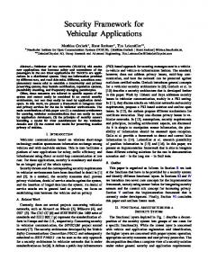
Fig. 1. Mapping of physical domain elements to objects.
(such as [14] and [17]) are applied, allowing classes and object instances, as well as the relationships among them, to be identified. Hence, objects may be understood as active entities that are able to intercommunicate through messages. The class and objects behavior can be depicted using Unified-Modeling-Language (UML)-based graphical notations [10] such as Statecharts or Activity Diagrams. System functionalities are depicted through Use Case and Sequence Diagrams. In our approach, the starting point of the analysis model consists in describing the whole system as a single element, according to Definition 1. Definition 1: The system description starts with a single object class. This class is considered to be the most external view of the analyzed system, which encapsulates more detailed components. Definition 2: The most external object class of the model is decomposed into more detailed objects. These more detailed objects are initially extracted from the industrial automation plant under analysis, and can be classified as active or passive objects, according to Definitions 3 and 4. Definition 3: Active object represents a concurrent element with autonomous reactive behavior. Definition 4: Passive object represents an element whose behavior is dependent on external stimulus. Active objects are generally used to describe the structure, behavior, and timing constraints of the technical plant physical components (e.g., sensors and actuators). On the other hand, passive objects reflect logical entities or data structures used within the system (e.g., logical representation of manufactured parts). The diagrams used for building such specification are the class and instance diagrams, according to the following definitions. Definition 5: The Class Diagram contains a general representation for the system components and their relationships. Definition 6: The Instance Diagram depicts the number of instances from the general model present in a specific situation or configuration. In the Class Diagram, the technical plant components are mapped to classes, while physical and logical connections among them are modeled as relationships (see Fig. 1). In order to reduce the number of objects/classes and relationships in each diagram, abstraction hierarchies, such as inheritance
BECKER AND PEREIRA: SIMOO-RT
and aggregation, are applied. Moreover, instead of building an analysis/simulation model from scratch, our methodology proposes that designers make use of predefined components, which should provide the necessary functionality to transform the identified conceptual objects into runtime entities. SIMOO-RT proposes an innovative way of describing the automation systems functional and timing requirements. This is achieved by describing how technical plant components should interact in order to achieve the desired behavior of the industrial automation being implemented. UML diagrams decorated with timing information are used for such purpose, as stated in Definition 7. Definition 7: Use cases, sequence diagrams, and state machines are used for depicting the desired behavior and functionality. According to the adopted development philosophy, the specified behavior can be validated through simulation, allowing users to have a better understanding of the specified semantics. One can understand a simulation model as a representation of an object, system, or an idea, showing the same behavior in the aspects related to the study of that model. In other words, a simulation model is nothing more than an abstraction of related entities that emphasizes important aspects of the problem from a given perspective. The simulation is obtained by executing the objects instances defined in the specification, according to the behavior specified in the classes’ dynamic models. Once this step is finished, the analysis phase is completed. Considering that the current model stage reflects the desired structure and dynamic behavior from its elements, a clear link is established between the computational elements (present in the model) and the real physical ones (present in the plant under automation). This link is achieved with the insertion of an extra object layer, called drivers layer, 1 which is used as a bridge between the logical and physical objects. Definition 8 formulates this idea. Definition 8: Drivers bridging the logical objects with the physical entities of the problem domain should be added into the model after the simulation step. In the next step, the target architecture for the system implementation should be defined. Normally, the target architecture envisioned is a distributed hardware architecture, consisting of low-cost processing units containing embedded microcontrollers. These units are interconnected through industrial buses, such as Profibus, CAN-Bus, and Fieldbus, or through generalpurpose protocols, like RS 232, and TCP/IP. This concept is formulated according to Definition 9. Definition 9: Patterns should be used for allocating active objects to the different processing units, as well as for mapping the communication between these active objects. For instance, communication patterns are based on standard technologies for distributed real-time OO computing, such as remote method invocation (RMI), RT-CORBA IIOP, and OLE for Process Control (OPC). Regarding the processing units, within the context of the SIMOO-RT project, both commercially available real-time operating systems compliant to the POSIX standard, such as QNX, as well as operating systems developed in 1This
is also referred to in the literature as the interface or wrapper layer.
423
academia, such as Linux and its real-time extensions (RTLinux), are considered as possible runtime environments. The final step, but not necessarily the last, since we are proposing an iterative process with a spiral life cycle, is to provide means for validating the application timing requirements. This should provide designers the necessary feedback to find not only performance bottlenecks of their models, but also to get qualitative feedback on how well timing requirements are being fulfilled. This requirement is formulated in Definition 10. Definition 10: Temporal validation is the process of checking the application’s runtime behavior against the specified timing requirements. Section III covers in detail the SIMOO-RT development environment. The main purpose of this environment is to group, as part of an integrated process, all development steps suggested by the present methodology. III. SIMOO-RT INTEGRATED ENVIRONMENT A. Overview SIMOO-RT [2] is a framework developed at the Federal University of Rio Grande do Sul (UFRGS), Porto Alegre, Brazil, aiming to cover all development steps of OO real-time systems, specially those used in industrial automation applications. It provides diagram editors and configuration folders to help designers follow the sequence of steps suggested in Section II. Following this idea, the so-called model editing tool (MET) provides support for the construction of the basic diagrams in the analysis process (Definitions 1–6): the class and instance diagrams. The former depicts relevant problem-domain concepts (such as the entities presented in Fig. 1) and their relationships, while the latter represents the real devices of a specific application. The instance diagram facilitates the system expansion, as it can keep an unlimited number of instances from the elements of the class diagram. One particular property of SIMOO-RT is to allow the association of timing constraints with class methods. It considers two basic timing requirements: periodicity and deadlines. The first denotes a periodic activation pattern of the method, while the second imposes a limitation on its execution time. Additionally, SIMOO-RT allows the definition of actions to be taken in case the specified deadline is violated. While this can be considered “exotic” by theoreticians in real-time systems, it has proven to be useful when dealing with real industrial automation applications, which are inherently safety critical. Such actions are usually used for alarming as well as bringing the technical plant to a safe state. This feature is very useful for dealing with transient-overload situations, which may happen sporadically in the long term of the system’s life cycle. Overtaking the scope of the (almost) independent elements depicted in the class diagram, it is possible to specify the system’s functionalities in a more generic way, as mentioned in Definition 7. Therefore, SIMOO-RT allows users to state the set of a system functionality by means of UML use cases [10]. This diagram offers designers the possibility of specifying the model context, that is, the messages exchanged by the proposed application functionalities (use cases) with the
424
IEEE TRANSACTIONS ON ROBOTICS AND AUTOMATION, VOL. 18, NO. 4, AUGUST 2002
external environment (actors). Furthermore, each use case can be detailed into UML sequence diagrams, allowing a more detailed description that consists of interobject interactions. In these diagrams, objects taking part in an execution scenario are disposed vertically, and exchanged messages are placed horizontally in a time-ordered manner. SIMOO-RT also allows designers to add timing restrictions to the exchanged messages, such as maximum waiting time for an invocation, maximum processing time for an incoming message, and the activation pattern of the message that triggers the scenario. A notation similar to the one proposed by Douglass in [14] is used to depict the message patterns. For modeling the systems elements’ dynamic behavior, the environment encourages the use of state-transition diagrams, whose formalism is based in Harel’s statecharts [19]. Three distinct basic types of states can be specified: initial, end, and normal state (operational). They are used, respectively, for instance creation and initialization, instance destruction, and for controlling user-defined modes of operation. Incoming messages are associated to actions (described as code templates) that objects have to undertake in reaction. These actions can be executed either during the state transition or while the object remains in a given state (a combination of Mealy and Moore formalism). Here, similar to class methods, timing constraints can also be imposed on the reactions that are part of the diagram semantic. More precisely, these actions represent state transitions (entering or exiting a state). For that, also, periodic activation patterns and deadlines (with exception handlers) can be specified. In order to allow the organization of predefined objects into a library of reusable elements, some additional tool support is available. The objects library contains information about the class description, interfaces, context dependencies, source code, and basic type. SIMOO-RT users can import or export objects to and from the objects library and the SIMOO-RT MET. The import–export functions also take into account inheritance dependencies of a given class, so that all necessary information is stored. As a way to test the logical correctness of the model specifications, SIMOO-RT includes a simulation engine [12]. Through this important feature, designers can check the behavior of the control algorithms, the correctness of the functional characteristics, and the overall system behavior. The simulation tool includes an animation/visualization library that enables designers to add visualization elements to the model, producing graphical animations from simulations. This feature has proven to be very effective when interacting with the final users of the application, since it anticipates the real vision of the product under development. SIMOO-RT also supports the description of the target architecture where the application should run. For this purpose, a similar version of the UML deployment diagram is adopted. It allows the definition of processing nodes, industrial network topologies, and specific communication protocols, as well as the mapping of the formerly defined objects to the processing nodes. It is assumed that each deployment diagram relates to a single instance diagram from the SIMOO-RT model. However,
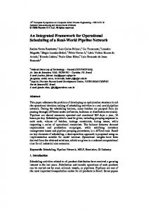
Fig. 2. Deployment information for the code generator.
a given instance diagram may be associated to multiple deployment diagrams, each one characterizing a possible implementation solution. The information described using the deployment diagram (see Fig. 2) is used as input for an automatic code generator. A generic high-level code structure is used to represent the generated application code. The information provided by the deployment diagram will serve to configure the hidden part of the code, i.e., the library calls that encapsulate the runtime infrastructure configuration. In Section III-B, the properties from the generated code and its execution engine are described in more detail. B. Code Generation and Runtime Environment Considering that the modeling paradigm adopted in SIMOO-RT is based on the concept of active objects, it is highly desirable to have an OO programming language as target for the automatic code generation, allowing a smooth transition from design to implementation. This target language should incorporate features for supporting concurrency and object distribution. The Active-Objects/C++ (AO/C++) language [32] was originally selected as the target language of SIMOO-RT, because it supports these desired features. This language combines the OO properties of standard C++ with the benefits of the RT-UNIX operating systems (e.g., QNX). The main idea of AO/C++ is to map the logically distributed model of the OO languages (e.g., C++), with the physically distributed model of the process-oriented RT-UNIX operating systems. The AO/C++ language adds some primitives to C++ in order to support the definition of active objects, time-triggered methods, and timing constraint specifications (e.g., deadline). An exception-handling code can be attached to methods with timing constraints in order to handle deadline violations. The number of primitives added to C++ was kept as minimal as possible, in order not to heavily modify the usual syntax of C++ programs. The C++ interobject communication is transparently mapped to the interprocess communication provided by RT-UNIX operating systems, so that the generated distributed programs are
BECKER AND PEREIRA: SIMOO-RT
425
schemes). The real computation of the active class methods take place in the generated OS process, which runs concurrently with other processes. The main goal of this strategy is to keep the AO/C++ code as similar as possible to the normal C++ code. This allows an interesting combination of the processes characteristics (concurrent execution, distributed) with those of the C++ runtime system, such as overloading, multiple inheritance, and encapsulation. Regarding the number of threads per object, in the current version each active object (more precisely each active instance of a class) corresponds to a process, i.e., a single-threaded approach is adopted. This cannot be considered a limitation, since attributes of AO/C++ active classes are not restricted to primitive data types. Instead, instances of other active classes are also allowed to be attributes (that means an active class can contain instances of other active classes). Different from multithread objects, which share common data space (class attributes), active objects are not exposed to internal race conditions, once there is no concurrent operation sharing the same set of attributes. Fig. 3. AO/C++ code structure.
very similar to C++ programs written for sequential, single-machine applications. Both synchronous and asynchronous communication are supported in AO/C++. Additionally, other interesting OO features from C++ compilers, especially multiple inheritance, polymorphism, and overloading, are also supported. Fig. 3 elucidates the language structure through the definition of an active class sensor, with a cyclic2 method Read(), and a timed3 method DataCondition(). Observe that there is no main() method associated to the class. Instead, it will be either timetriggered (activated by cyclic methods) or event-triggered (activated by any other method). Programs written in AO/C++ are parsed by a preprocessor and then converted to a standard C++ code, which includes calls to the AO/C++ library, which can be configured according to the operating system and to the network protocol. Currently, the code generator is able to generate applications for Ethernet and CAN-bus networks running, respectively, the TCP/IP and the publisher/subscriber protocols. These communication infrastructures can be used for interconnecting processing nodes running QNX, Linux, and Clinux operating systems. Nevertheless, our code generator can only support four combinations: QNX+TCP/IP, Linux+TCP/IP, Linux+ CAN and Clinux+ CAN. It must be highlighted that this is not a modeling limitation, but a restriction of this version of the tool. In [11], the mapping of the original AO/C++ RMI-based communication for the publisher/subscriber protocol is discussed in detail. Considering the runtime configuration, a special constructor is defined for each active class, which generates an operating system process that is attached to a special interface. This interface interacts with another implementation of the class that has modified methods to provide transparent RMI or message publishing (when using publisher/subscriber communication 2Method 3Method
with periodic activation. with an associated deadline.
C. Model Validation Validation capabilities is another feature included in the SIMOO-RT environment. In [4] an automatic monitoring scheme for such applications is presented. The definition of which classes or class methods are to be monitored can be configured in the SIMOO-RT models, and based on that information, the generated code will be automatically instrumented in order to allow an observation of the runtime behavior. All incoming steps are automatic and hidden from the developers through scripts. The AO/C++ code is translated into distributed C++ code, and the output files are then instrumented by running the mc4p precompiler [25]. The precompiler places software triggers using fixed syntactical rules. In order to preserve all information from the OO environment, an event should always contain information about its static context (event type, class, and the method in which it occurred) as well as its dynamic context (object ID, process ID, and time stamp). The output of the previous step is compiled using a standard C++ compiler and linked with a runtime library. The result is a ready-to-run application that now can be executed in the target environment. A test run will automatically create per node event traces that are collected and finally visualized by the Jewel++ tool [4]. This tool is suitable for the observation of real-time applications, as it puts emphasis on low interference. It is also capable of using or even creating a system-wide synchronized time base, and to observe the common system-level events that are important for any real-time system. The adopted model validation scheme (described in detail in [3]) consists of an architecture intended to provide a feedback to designers regarding the application’s temporal behavior (validation of its timing requirements). After finishing the monitoring phase, the generated output is used for the validation of the modeled timing constraints. In the proposed architecture, the constraints defined during modeling are mapped to timing predicates. Here, two basic forms of event occurrences are supposed, cyclic and activities. The first one is important because
426
IEEE TRANSACTIONS ON ROBOTICS AND AUTOMATION, VOL. 18, NO. 4, AUGUST 2002
Fig. 5. Scenario depicting the normal state of operation from Tank class.
Fig. 4.
Overview and class/instance diagrams of the selected case study.
periodical activation is very common in real-time applications, and is also suitable to be expressed by SIMOO-RT timing constraints. On the other hand, the activities abstraction, specified in SIMOO-RT on the sequence diagrams, is useful to represent event sequencing and to specify end-to-end timing requirements. In order to allow the validation of timing requirements, it is necessary to capture runtime information about the application. This functionality is achieved following the monitoring scheme provided by mc4p. Validation results are visualized using graphical notations as close as possible to the abstraction used by designers. To achieve this goal, the designer can specify, within the SIMOO-RT modeling diagrams, the event occurrences that he/she is interested in. This property is important to highlight because it acts like a filter for the monitoring results, since it would be impossible to express all monitoring results in a single chart. The system allows both the validation of specific event occurrences (for instance, to ensure that a sampled sensor signal occurs with a minimal jitter regarding a predefined sampling period) as well as event sequences (end-to-end requirements). Among the several graphical notations available for visualization, the Histogram Graph has proven to be very useful for validation periodic event occurrences. It elucidates the temporal distribution in occurrences of particular events, within the timing interval that represents the requirement. For end-to-end requirements validation, Gantt Diagrams appear as a very expressive visual notation for describing event ordering. IV. CASE STUDY In order to better illustrate the methodology presented in Section III, a case study will be detailed in this section. Due to the
paper’s length limitation, only a small subset of a more complex industrial automation plant (as shown in Fig. 4) was selected. A small subset of a chemical plant automation problem, which consists of a tank, a level sensor, and a pump was selected and the tank level control process will be used for illustration purposes. The starting point of the OO model for this case study is the definition of the conceptual model, which results in the definition of a class diagram and an instance diagram (even if these elements are not completely populated with attributes and methods). After that, with the design of the use case diagrams, the set of use cases containing the system’s functionalities are defined. For this specific study, three use cases were selected: 1) system configuration; 2) level control; and 3) timing requirements monitoring. The first use case deals with the task of reading user commands (such as start, stop, level change) and configuring the controller (encapsulated in the tank class) when necessary. The second one describes the periodical sampling of sensor data, the tank level control process, and corresponding pump actuation. Finally, the third use case depicts the system execution monitoring. As the control use case is the most critical one for the system, it will be used to highlight the constraints applied to the model. The Tank class encompasses the most critical system functionalities, once it interacts with the actors User, LevelSensor, and Pump to execute the control algorithm. This class is considered to be in one of the following operational stages (which are mapped as states): Normal, Exception, Overload, and Alarm. As already implied by its name, the Normal state indicates normal operation of the class execution flow. A scenario (see Fig. 5) is used to represent the usual closed-loop control interaction pattern. First, the level sensor is read, then the control algorithm is computed, and finally the pump status is set. If one of these steps fails (detected by the expiration of the associated deadline), an alternative operation mode is triggered. The state Exception is triggered by the event Timeout1, meaning that there was no answer from the level sensor within the specified time (100 ms) (for instance, this triggers the activation of an open-loop control algorithm). Another possible state is Overload, that is triggered if the control method does not meet its deadline. This situation triggers the event Timeout2, starting an error-correction routine. The last state is Alarm, triggered by the timeout in the call of
BECKER AND PEREIRA: SIMOO-RT
427
TABLE I EVENTS USED IN THE CASE STUDY
Fig. 6. Snapshot of the tank system simulation. TABLE II TIMING REQUIREMENTS ON EVENTS
Fig. 7.
Class diagram with the drivers layer.
the Command() method, from class Pump (event Timeout3). As soon as the modeling phase is completed, a simulation is undertaken in order to test the logical behavior of the model. A snapshot of the animation produced by the simulation is presented in Fig. 6. Up to now, the designed model was intended to be tested within a simulation environment. Nevertheless, to move toward using it in a real environment, it needs to be adapted for interacting with real technical plant devices. This development phase corresponds to the addition of specific drivers into the model, as discussed in Section II. This causes a modification in the class diagram, because the corresponding drivers substitute the Process class (see Fig. 3), which is the entity that provided the simulated behavior. In this case study, drivers for the Sensor and the Pump classes are added as shown in Fig. 7. Completed the modeling cycle, the target architecture for the developed model is defined. In this case, the modeled object instances are deployed to an architecture consisting of two Pentium PCs running the QNX operating system, interconnected through a TCP/IP network. The initial deployment configuration consisted of all objects being mapped to a single execution
node. Events of interest for this configuration are selected for instrumentation (see Table I), so that their occurrences could be collected and analyzed. The timing behavior expressed in the sequence diagram as timing annotations is mapped to predicates, to be further used within the time validation tool. Table II shows the requirements captured from the sequence diagram presented in Fig. 5. To increase the spectrum of the experiments, three different target architectures were configured and the resulting behavior was monitored for validation purposes. The three architectural alternatives were as follows: 1) all objects instantiated into a single machine; 2) with the level sensor object instantiated on a remote node; 3) similar to case 2, with a forced (simulated) network failure. The integrated validation tool allowed several important timing analyses to be performed. For instance, the execution cycle of the Tank class control scenario in Normal state of operation was validated using the timing requirement “CYCLIC E1@-1 [500, 10]” (see Table II). Results show that the observed periodicity of the cyclic method CtrLoop() from Tank class is basically the same in all three experiments. The average period was about 3 ms smaller than expected, and a few occurrences showed deviations of up to 1 ms. The histogram in Fig. 8 (derived from Experiment B) depicts this situation, presenting
428
IEEE TRANSACTIONS ON ROBOTICS AND AUTOMATION, VOL. 18, NO. 4, AUGUST 2002
Fig. 8. Periodicity of Tank class control scenario in Normal state.
Fig. 9. Comparison of cases 1 and 2.
the number of occurrences of the event E1 during the monitored interval. The execution time of the tank control scenario presents a variation of 23% more time for Experiment B (80 ms) in comparison to Experiment A (65 ms). Differences in the execution times can be related to the communication overhead between the controller and the sensor object, when instantiated into a remote node. This communication overhead can be observed in the Gantt diagrams of Fig. 9, on which one can compare the delay from Event E2 (requesting sensor information) to Event E9 (message arrival in the sensor), in Experiment A (local sensor) and in Experiment B (remote sensor). In this diagram, horizontal bars are related to the specified timing requirements, showing the validity interval on which a given event must occur (see Table II). The last analysis of the case study focuses on the failure scenario found in the third experiment. The introduced network failure produces a timeout in the RMI of method Read(), which is represented by event E10. This timeout triggers the transition from Normal to Exception state, changing the set of requirements. In [15] a more comprehensive comparison of the results obtained with different architectures (operating systems, programming languages) is presented. V. RELATED WORKS This section aims to compare the proposed approach, concerning the main aspects of SIMOO-RT methodology and its
supporting tools, with some related work presented in the literature. The first point that is highlighted concerns the adopted object model. The time-triggered (TT) message-triggered object (TMO) model proposed by Kane Kim [22]–[24], also suggests that real time should be presented at a high-level, implementation-independent way. The main feature of the TMO model is a clear separation between TT and message-triggered (MT) methods. This separation enables the runtime engine to have a strict control among the possible execution conflicts between the highest priority TT methods, and the lowest priority MT methods. We consider this approach very complementary to the one presented in this paper, and some efforts for integrating the SIMOO-RT environment with the TMO programming model have already been done. Another interesting aspect to be discussed regards the objects architectural definition. Although one of the main advantages of OO models is to allow a direct mapping of problem-domain semantics, leading to intuitive and easier to understand models, not always do such models lead to good runtime architectures. In a collaboration project with researchers from the University of Lisboa, Portugal, some approaches toward an automatic identification of objects, based on modularity and testability metrics, has been developed (see [5], [6], [13]). Regarding the SIMOO-RT integrated environment, the authors do not know another similar tool which provides support for the whole development phase suggested by the proposed methodology. Many existing commercial tools provide good support for modeling aspects. Concerning model validation using simulation and automatic code generation, tools such as I-Logic Rhapsody, Rational Rose Real-Time, Telelogic Tau Suite, and the Artisan Real-Time Studio, just to name a few, also provide suitable support. A missing feature of these tools is that they do not provide designers feedback concerning the evaluation of timing properties. Although some proposals of integrating such modeling tools with existing real-time programming and debugging environments already exist, the resulting tools are still missing a more comprehensive support from requirements to implementation. Considering the AO/C++ target language, the new generation of middleware for distributed objects computing, like CORBA [28], [41], DCOM [26], [27], and Java-RMI [42], support similar and even more enhanced distribution facilities. The problem resides in the real-time aspects, where they do not provide support for timing requirements specifications. Implementations for the RT-CORBA [29], [36], [37] and RT-Java [8] standards, although very powerful conceptually, are still under development. The underlying methodology and concepts proposed in this paper are generally applicable, and not restricted to the AO/C++ programming model. Current research done by the authors (see [43]) includes the use of recently published real-time object models, such as the RT-UML [30] notation and the RT Specification for Java API [8]. VI. CONCLUSION This paper introduced SIMOO-RT, a framework to support the whole development cycle of industrial automation real-time applications with the use of distributed real-time objects. The results obtained in the developed case studies indicate that the pro-
BECKER AND PEREIRA: SIMOO-RT
posed methodology is effective in covering the suggested design aspects. The simulation facility and the automatic code generator provide designers with valuable support to reduce programming and debugging time. Also, it provides designers with valuable feedback regarding model-related high-level information about timing specifications. In addition, the various graphical diagrams integrated in the architecture give developers the necessary conditions to analyze and validate the application temporal behavior. The main point to highlight is that the tool provides a fully integrated development methodology and tool support, assisting users from initial specification to code generation and timing requirements validation during runtime. ACKNOWLEDGMENT Thanks are given to Prof. Kaiser of the University of Ulm, Germany; Prof. Nett and Dr. Gergeleit of the University of Magdeburg, Germany; and Prof. Halang of the University of Hagen, Germany, partners in the Brazil–Germany cooperative research program, for their important comments and suggestions during the development of this project. REFERENCES [1] M. Awad, J. Kuusela, and J. Ziegler, Object-Oriented Technology for Real-Time Systems: A Practical Approach Using OMT ad Fusion. Englewood Cliffs, NJ: Prentice-Hall, 1996. [2] L. B. Becker and C. E. Pereira, “From design to implementation: Tool support for the development of object-oriented distributed real-time systems,” in Proc. 12th Euromicro Conf. Real-Time Systems, Stokholm, Sweden, June 2000, pp. 108–115. [3] L. B. Becker, R. Wild, and C. E. Pereira, “An architecture for validating object-oriented timing specifications,” in Proc. 5th World Multiconf. Systemics, Cybernetics, Informatics, Orlando, FL, July 2001. [4] L. B. Becker, C. E. Pereira, E. Nett, and M. Gergeleit, “An integrated environment for the complete development cycle of an object-oriented distributed real-time system,” in Special Issue on ISORC Series, Computer Systems Science & Engineering. Leics, UK: Troubador, 2001, vol. 16, pp. 89–96. [5] L. B. Becker, C. E. Pereira, O. Dias, I. Teixeira, and J. Teixeira, “On identifying and evaluating architectures for real-time applications,” In Contr. Eng. Practice, vol. 9, pp. 403–409, 2001. , “Optimizing functional distribution in complex system design,” in [6] Proc. Int. Workshop Distributed and Parallel Embedded Systems, Paderborn, Germany, Oct. 2000, pp. 75–86. [7] T. Bihari and P. Gopinath, “Object-oriented real-time systems: Concepts and examples,” IEEE Computer, vol. 25, pp. 25–32, Dec. 1992. [8] G. Bollella, J. Gosling, and B. Brosgol, The Real-Time Specification for Java. Reading, MA: Addison-Wesley, 2000, p. 195. [9] G. Booch, Object-Oriented Development. Redwood City, CA: Benjamin Cummings, 1991. [10] G. Booch, I. Jacobson, and J. Rumbaugh, The Unified Modeling Language User Guide. Reading, MA: Addison-Wesley, 1999. [11] C. Brudna, C. Mitidieri, C. E. Pereira, and L. Kaiser, “Methodology and tool support for developing distributed real-time applications,” in Proc. 25th Workshop Real Time Programming, Palma de Mallorca, Spain, 2000, pp. 211–216. [12] B. Copstein, F. Wagner, and C. Pereira, “SIMOO—An environment for the object-oriented discrete simulation,” in Proc. 9th Eur. Simulation Symp. (ESS’97), Passau, Germany, Oct. 1997, pp. 21–25. [13] O. Dias, I. Teixeira, and J. Teixeira, “Metrics and criteria for quality assessment of testable Hw/Sw system architectures,” J. Elect. Testing, Theory, Applicat. (JETTA), vol. 11, no. 1/2, pp. 149–158, 1999. [14] B. Douglas, Real-Time UML: Design Efficient Objects for Embedded Systems. Reading, MA: Addison-Wesley, 1998. [15] A. Flores et al., “Quantitative evaluation of distributed object-oriented programming environments for real-time applications,” in Proc. 2nd IEEE Int. Symp. Object-Oriented Real-Time Distributed Computing, Saint-Malo, France, 1999, pp. 133–138.
429
[16] M. Gergeleit, E. Nett, and M. Mock, “An adaptive approach to objectoriented real-time computing,” in Proc. 1st IEEE Int. Symp. ObjectOriented Real-Time Distributed Computing, Kyoto, Japan, 1998, pp. 342–349. [17] H. Gomaa, Designing Concurrent Distributed, and Real-Time Applications With UML. Reading, MA: Addison-Wesley, 2000. [18] W. Halang and A. Stoyenko, Constructing Predictable Real-Time Systems. Norwell, MA: Kluwer, 1991. [19] D. Harel, “Statecharts: A visual formalism for complex systems,” in Science of Computer Programming 8. Amsterdam, The Netherlands: North-Holland, 1987, pp. 231–274. [20] IEEE Int. Symp. Real-Time Distributed Object Computing—Conf. Series. [21] R. Kemmerer and C. Ghezzi, “Guest editors introduction: Specification and analysis of real-time systems,” IEEE Trans. Software Eng., vol. 18, pp. 766–767, Sept. 1991. [22] K. Kim et al., “A real-time object model RTO.k and an experimental investigation of its potentials,” in Proc. COMPSAC’94, Taipei, Taiwan, R.O.C., 1994, pp. 392–402. , “Real-time object-oriented distributed software engineering and [23] the tmo scheme,” Int. J. Software Eng. Knowledge Eng., vol. 2, pp. 251–276, Apr. 1999. , “API’s for real-time distributed object programming,” IEEE Com[24] puter (Special Issue on OO RT Distributed Computing), vol. 33, pp. 72–80, June 2000. [25] F. Lange, R. Kroeger, and M. Gergeleit, “JEWEL: Design and implementation of a distributed measurement system,” IEEE Trans. Parallel Distrib. Syst., vol. 3, pp. 657–671, Nov. 1992. [26] “Microsoft. DCOM Technical Overview. Tech. Rep. Microsoft Windows NT Server White Paper,”, Seattle, WA, 1996. [27] (2000) Microsoft. Distributed Component Object Model (DCOM): Downloads, Specifcations, Samples, Papers, and Resources for Microsoft DCOM, Seattle, WA. [Online]. Available: http://www.microsoft.com/com/tech/dcom.asp [28] “OMG. Corba Specification v. 2.2,”, Needham, MA, OMG Document formal/98-12-01, 1998. [29] “OMG. Real-Time Corba,”, Seattle, WA, OMG Document orbos/99-02-12, 1999. [30] “OMG. UML Profile for Schedulability, Performance, and Time Specification,”, Seattle, WA, OMG document n. ptc/02-03-02. [31] C. E. Pereira and P. Darscht, “Using object-orientation in real-time applications: An experience report,” in Proc. TOOLS Eur. 94, Versailles, France, 1994. [32] C. E. Pereira, “Real time active objects in C++/real-time UNIX,” in Proc. ACM SIGPLAN Workshop Languages, Compiler, Tool Support for Real-Time Systems, Orlando, FL, 1994. , “Applying object-oriented concepts to the development of [33] real-time industrial automation systems,” in Proc. WORDS-97, IEEE Workshop on Object-Oriented Dependable Systems, 1997, pp. 264–269. [34] E. Shokri and P. Sheu, “Real-time distributed object computing: An emerging field,” IEEE Computer, pp. 45–46, June 2000. [35] J. Rumbaugh, Object Oriented Modeling and Design. Englewood Cliffs, NJ: Prentice-Hall, 1991. [36] D. Schmidt, D. Levine, and S. Mungee, “The design of the tao real-time object request broker,” Comp. Commun., vol. 21, no. 4, Apr. 1998. [37] D. Schmidt and F. Kuhns, “An overview of the real-time CORBA specifcation,” IEEE Computer (Special Issue on OO RT Distributed Computing), vol. 33, pp. 56–63, June 2000. [38] B. Selic, “Turning clockwise: Using UML in the real-time domain,” Commun. ACM, vol. 42, pp. 46–54, Oct. 1999. [39] B. Selic, G. Gullekson, and P. Ward, Real-Time Object-Oriented Modeling. New York: Wiley, 1994. [40] B. Selic, “A generic framework for modeling resources with UML,” IEEE Computer (Special Issue on OO RT Distributed Computing), vol. 33, pp. 64–71, June 2000. [41] S. Vinoski, Advanced CORBA Programming With C++. Reading, MA: Addison-Wesley, 1999. [42] A. Wollrath, R. Riggs, and J. Waldo, “A distributed object model for the java system,” USENIX Comput. Syst., vol. 9, no. 4, pp. 265–290, 1996. [43] R. Holz, L. Becker, and C. E. Pereira, “On mapping RT-UML specifications to RT-Java API: Bridging the gap,” in Proc. 5th IEEE Symp. Object-Oriented Real-Time Computing ISORC’2002, vol. 9, Washington, DC, May 2002, pp. 348–355.
430
IEEE TRANSACTIONS ON ROBOTICS AND AUTOMATION, VOL. 18, NO. 4, AUGUST 2002
Leandro B. Becker (S’01) received the B.S. degree in 1997 from the Federal University of Santa Maria (UFSM), Brazil, and the M.Sc. degree in 1999 from the Federal University of Rio Grande do Sul (UFRGS), Porto Alegre, Brazil, both in computer science. He is currently working towards the Ph.D. degree in the Computer Science Institute, Federal University of Rio Grande do Sul (UFRGS). His research interest is the application of the object-oriented paradigm in the development of real-time systems, with emphasis on industrial automation applications.
Carlos E. Pereira (M’95) received the B.S. degree with honors in electrical engineering and the M.Sc. degree in computer science, both from the Federal University of Rio Grande do Sul (UFRGS), Porto Alegre, Brazil, in 1987 and 1990, respectively, and the Dr.-Ing. degree in electrical engineering from the University of Stuttgart, Stuttgart, Germany, in 1995. He is a Professor in the Electrical Engineering Department, UFRGS, where he leads a research group in the field of industrial automation and control. His research focuses on methodologies and tool support for the development of distributed real-time systems, with special emphasis on industrial automation applications and the use of distributed objects over industrial communication protocols. He is currently Vice-Chair of the IFAC Technical Committee on Real-Time Software Engineering and Associate Editor of the IFAC Journal Control Engineering Practice.