Full-range complex spectral domain (SD) optical coherence tomography (OCT) ..... The authors wish to thank Harald Sattmann and Christoph Wölfl for technical ...
Simple technique for full-range complex spectral domain optical coherence tomography Bernhard Baumann, Michael Pircher, Erich Götzinger, Christoph K. Hitzenberger Medical University of Vienna, Center for Biomedical Engineering and Physics Währinger Straße 13, A – 1090 Vienna, Austria
ABSTRACT Full-range complex spectral domain (SD) optical coherence tomography (OCT) enables the removal of the complex conjugate artefact by measurement of the phase of the spectral interference signal. In order to retrieve the complex signals, the phase of the OCT signal has to be modulated in a well-defined way. For this purpose, different devices, such as piezo mirrors or electro-optic modulators, have been added to the instruments reported so far. We present a SD-OCT system capable of elimination of the complex conjugate artefact without using any additional phase modulating devices. A stable phase modulation is generated by displacing the galvo scanner mirror used for 2D imaging in such a way that the probe beam hits the mirror off its axis of rotation. Only a single measurement is necessary for the reconstruction of each complex valued depth profile, thus allowing for high-speed imaging. The method is demonstrated for full-range imaging of the anterior segments of human eyes in vivo. Keywords: Optical coherence tomography, biomedical imaging
1. INTRODUCTION Spectral domain (SD) optical coherence tomography (OCT) has shown to have considerable advantages in terms of sensitivity and imaging speed compared to time domain OCT.1,2 SD-OCT is based on the fact that each path length difference between beams in the reference arm and sample arm induces a proportional modulation frequency in the spectrum of the interfered light beams.3 The depth scan information is retrieved by an inverse Fourier transform of the spectral interferogram. However, since the spectral interferogram is recorded as a real valued function of frequency, its (inverse) Fourier transform is Hermitian which results in an image symmetric about zero path difference. In order to avoid this overlap of structures located at positive and negative path differences with respect to the reference mirror, usually only half the depth range is used for imaging. In complex SD-OCT techniques, which have been developed in recent years, also the phase of the spectral interference signal is measured which gives access to the complex-valued interferogram, thus allowing to use the full depth range for imaging. First complex SD-OCT techniques presented required five measurements with different phase shifts provided by the reference mirror to reconstruct one depth profile.4,5 By applying phase shifts of π/2, only two consecutive measurements were necessary in improved versions of the phase shifting algorithm.6,7 Depth range doubling requiring just one measurement per sampling position was achieved with swept source based Fourier domain OCT setup by employing acousto-optic frequency shifters.8 Recently, full-range SD-OCT techniques were presented using the linearly increasing phase shift generated by uniform movement of the reference mirror during the acquisition of each B-scan.9,10 In this paper we present a simple method for full-range complex (FRC) SD-OCT which – in contrast to techniques presented so far – does not require any additional phase shifting devices and which easily can be implemented in existing SD-OCT setups in order to double the accessible image depth.
Coherence Domain Optical Methods and Optical Coherence Tomography in Biomedicine XII, edited by Joseph A. Izatt, James G. Fujimoto, Valery V. Tuchin, Proc. of SPIE Vol. 6847, 68471N, (2008) 1605-7422/08/$18 · doi: 10.1117/12.761687 Proc. of SPIE Vol. 6847 68471N-1 2008 SPIE Digital Library -- Subscriber Archive Copy
2. METHODOLOGY The following section gives a brief overview of the post-processing steps and the experimental realization of the phase shifting. A more detailed description can be found in reference [11]. 2.1 Mathematical perspectives In SD-OCT, information about the light intensity back-scattered from the sample is enciphered as modulation frequencies in the cross spectral density function of the interfered beams from sample and reference arm. The amplitude of such a modulation is proportional to the back-scattered intensity whereas the modulation frequency is linearly related to the path length difference between the beams returning from a sample interface and the reference mirror, respectively. Intensity images are retrieved from the two-dimensional (2D) spectral interferogram by inversely Fourier transforming the data for each lateral scan position x which is shown by the white arrow in Fig. 1(a). Now, since S(x,k) is recorded as a real-valued function, the signs of the modulating frequencies and thus the sign of z in position space can not be resolved. Due to this ambiguity of the modulation frequencies’ signs, image features located at positive and negative depths will overlap.
a
Position space
Spectral domain
J
I FT-1
°i
Spatial frequency domain
k, ______ S)
z
________
* ___________ x
Position space
Spectral domain
Spatial frequency domain
(u,k) B(u,k)
I
k1 HiIbertFJ.
I
k+
•II
U
J'.Heaviside
ii•
b
Fig. 1. Flow-chart illustration of OCT signal reconstruction for (a) conventional SD-OCT without phase-shifting and (b) FRC-SD-OCT after constant phase shifts were applied. The asterisk in (a) marks the regular procedure for SD-OCT image reconstruction.
In order to reconstruct the complex-valued spectral interferogram and thus to be able to use the full depth range for imaging, phase shifts ∆Φ are induced between adjacent A-scans (cp. S(x,k) in top of Fig. 1(b)). If now Fourier transforms are performed not column-by-column but line-by-line, the spectrum in spatial frequency domain B(u,k) will be shifted from the center u = 0 to both the positive and negative ranges. On the right-hand side of Figs. 1(a) and 1(b), respectively,
Proc. of SPIE Vol. 6847 68471N-2
this step is illustrated (black arrows). By applying the Heaviside step function Θ(u), only the spectrum B(u,k) shifted to the positive range remains. An inverse Fourier transform line-by-line yields the complex-valued spectral interferogram Ŝ(x,k), which – after being inversely Fourier transformed column-by-column – results in the full-range OCT image I(x,z).9 Two conditions must prevail for the algorithm in order to yield optimal suppression of the complex conjugate artifacts: (i) the total width of the spectrum in spatial frequency domain B(u,k) must not exceed half of the Fourier space; (ii) the phase shift ∆Φ applied between neighboring A-scans is preferably chosen such that B(u,k) and its complex conjugate, B (u , k ) , will be shifted to the center of the positive and negative ranges, respectively, such that an optimal separation of
B(u,k) and B (u , k ) is achieved. For reconstruction of the complex-valued spectral interferogram Ŝ(x,k) from its real part S(x,k), instead of the algorithm described above, also the Hilbert transform applied line-by-line can be used.10 Provided that conditions (i) and (ii) hold, the outcome of the Hilbert transform will be the quadrature components of S(x,k). 2.2 Experimental setup – Generation of phase shifts
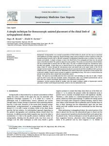
A sketch of the experimental setup is shown in Fig. 2. The system was based on a free space Michelson interferometer with a superluminescent diode (SLD) emitting at λ0 = 840 nm (∆λFWHM = 50 nm) as a light source. In the sample arm, the beam was scanned across the sample by means of an X-Y galvo scanner, which was mounted on a two-axis translation stage. An achromatic lens with a focal length of 80 mm was used for imaging. The spectrometer consisted of a transmission diffraction grating with 1200 lines/mm, an achromatic doublet lens (f = 200 mm), and a line scan CCD camera (2048 pixels, each 14 × 14 µm²). The spectrometer parameters allow for a total image depth range of 6.6 mm (2 × 3.3 mm). With a sample arm power of 1.3 mW and a camera integration time of 100 µs, a sensitivity of 101 dB was measured close to zero path delay z = 0; at z = ±2.5 mm, the sensitivity dropped by 13 dB.
a
b
RM
CCD
ND
∆z
s
L FC
GS
BS
∆β
DG FC FC
SLD
f
L S
Fig. 2. (a) Sketch of instrument. SLD: superluminescent diode, FC: fiber coupler, BS: beam splitter, ND: variable neutral density filter, RM: reference mirror, GS: galvo scanner mirror mounted on two-axis translation stage, L: lens, S: sample position, DG: transmission diffraction grating, CCD: line scan CCD camera. (b) Sketch of sample beam geometry. During one scan across an angle of ∆β, the sample beam path is altered by ∆z when the galvo mirror’s pivot axis is displaced by a distance s. f denotes the focal length of the imaging lens.
After data acquisition by means of CameraLink, a high speed frame grabber board, and a personal computer (P4, 3.2 GHz, 2 GB RAM), the following post processing steps were performed: fixed pattern noise removal, remapping to equidistant sampling in k-space, line-by-line Hilbert transform along x (as described above), inverse Fourier transform along k. In order to generate the phase shifts ∆Φ necessary for shifting the spectral components B(u,k) away from u = 0, the galvo scanner mirror used for scanning the sample beam in x-direction was positioned in such a manner that the probing beam hit it slightly aside its pivot axis (cf. Fig. 2(b)). The galvo scanner mirror was mounted on a translation stage in order to
Proc. of SPIE Vol. 6847 68471N-3
allow for precise adjustment of this beam offset. The path length imbalance during one B-scan of ∆β is approximately ∆z ~ s∆β, when the mirror’s pivot axis is displaced by a distance s from the interferometer sample beam.12 Consequently, a phase shift ∆Φ = 4π∆z/(Nλ) is introduced between adjacent A-scans with N being the number of A-scans per B-scan. Fig. 3(a) shows how the phase is constantly increased across a B-scan of 1000 A-scans (scanning angle ∆β = 12°). The linear relationship between the offset s of the galvo mirror’s pivot axis with respect to the sample beam and the phase shift ∆Φ induced is demonstrated for three different depth positions z of the test sample (black anodized aluminum part) in Fig. 3(b).
a
b
1600 -1 1400
00
]
niulated PhaseShift
.. 1200
000
-
°
Regression:y=4i.553+1.633*x
0
•o
0
$00 o z = +0.83mm
0 z+1.39mm 0 z = -0.98mm
0
2°: 0
100 200 300 400 500 600 700 800 900 1000
-1,0
A-Scan Number
-0,5
0,0
0,5
1,0
Mirror Offset [mm]
Fig. 3. (a) Cumulated phase shift along one transversal line of a B-scan image. Dash-dotted line: linear regression. (b) Phase shift ∆Φ induced between neighboring A-lines shows linear dependency on the offset s of the scanner mirror’s pivot axis with respect to the sample beam.
When the mirror offset s is chosen such that the phase shift induced between neighboring A-scans amounts to ∆Φ = π/2 or ∆Φ = -π/2, the spectrum B(u,k) in spatial frequency domain will be shifted to the center of the positive and negative half spaces, respectively. Then optimal suppression of the complex conjugate signal is to be expected. The theoretically achievable extinction ratio ER (i.e. the ratio of a signal and its complex conjugate) equals the signal to noise ratio. In practice, the theoretical ER is reduced by both, effects that broaden the spectrum B(u,k) in spatial frequency domain and effects that induce an additional phase shift ∆Φadd such that B(u,k) is shifted away from the center of the positive and negative half space. A reduction of ER arises as soon as a part of the spectrum overlaps beyond u = 0, since by this overlapping part an according amount of the signal is flipped from +z to –z and vice versa. The algorithm’s efficiency is reduced by the chromatic phase error due to the wavelength dependency of the generated phase shift, ∆Φ(λ) = 4π∆z/(Nλ). Moreover, by the non-zero diameter of the beam, light traveling at different distance from the beam center is impinging at different offsets s from the mirror’s pivot axis. Hence, not a single phase shift but a distribution of phase shifts ∆Φ(s) is generated in dependency of the sample beam diameter. Consequently, B(u,k) will be broadened. The initial shape of B(u,k) is given by the transversal object structure and sampling properties. If sample motion or vibrations in one of the interferometer’s arms occur, an additional phase ∆Φadd is induced.
3. RESULTS The instrument and the algorithm described in the previous section were used for in vivo imaging of the anterior chamber of healthy human subjects. The mirror offset s was set such that a phase shift of π/2 was generated while a lateral scan of 12° was performed. Fig. 4 shows results derived from the same spectral data consisting of 1000 A-scans. The top image shows an OCT image obtained by just inversely Fourier transforming the spectral data after rescaling and fixed pattern noise removal as it is usually done in SD-OCT. The FRC-SD-OCT algorithm was applied for the image below. In contrast to the upper image, where the true object structure is obscured by the overlapping mirror image, the complex conjugate artifacts were efficiently suppressed.
Proc. of SPIE Vol. 6847 68471N-4
a
b
1mm
Fig. 4. B-scan images of human anterior segment in vivo. (a) OCT image obtained by inverse FFT of the real-valued spectral data. (b) Full-range image obtained by complex signal reconstruction using FRC-SD-OCT algorithm.
a
b
• •-
c a
Fig. 5. Full-range complex polarization-sensitive SD-OCT images of human anterior chamber in vivo. (a) Reflectivity image. (b) Retardation image. (c) Axis orientation image. [color online]
Proc. of SPIE Vol. 6847 68471N-5
The FRC-SD-OCT was also implemented in our polarization-sensitive (PS) SD-OCT system.13 Just like for the intensity based system described above, only a small modification of the galvo scanner mirror position used for transversal scanning of the beam was necessary to enable a two-fold increase of the accessible imaging range. Again, the scanning unit was mounted on two translation stages to allow for precise adjustment of the mirror offset s. Then, s was set such that a phase shift of π/2 was induced between adjacent A-scans. The integration time of the spectrometer cameras was set to 50 µs, and a power of 2.5 mW was used to illuminate the sample. After data acquisition, the spectral data of both polarization channels was processed as described in section 2. Once the complex OCT signals I(x,z) = A(x,z)exp[iΦ(x,z)] had been calculated for both channels, full-range images of reflectivity, phase retardation, and optic axis orientation were derived in the usual way.14 In Fig. 5, full range complex PS SD-OCT images of human anterior chamber in vivo are shown. Fig. 5(a) shows the reflectivity, Fig. 5(b) the retardation and Fig. 5(c) the axis orientation. The color scales (blue-green-red) in the retardation and axis orientation images cover the unambiguous ranges of 0° − 90° and -90° − 90°, respectively. Clearly, dissimilar polarizing properties of the different structures can be distinguished. While the cornea shows a birefringent character, the stroma of the iris preserves the polarization state of the light, whereas the pigment epithelium of the iris scrambles the polarization state.15,16
4. CONCLUSION In this paper, a simple technique for FRC-SD-OCT was presented which – in contrast to previously reported full-range techniques – omits any additional phase shifting devices. The phase shifts required by the complex signal reconstruction algorithm were generated by simply offsetting the galvo scanner mirror’s pivot axis from the sample beam. The qualitative measurements on a test sample as well as B-scan images of human anterior chamber in vivo prove the potential of the technique for easy implementation of full-range SD-OCT imaging. Furthermore, the full-range technique was implemented in an existing polarization-sensitive SD-OCT instrument and successfully used for in vivo polarizationsensitive imaging with a two-fold increase of imaging depth.
ACKNOWLEDGEMENTS The authors wish to thank Harald Sattmann and Christoph Wölfl for technical assistance. Financial support of the Austrian Science Fund (FWF grants P16776-N02 and L126-N08) is gratefully acknowledged.
REFERENCES 1. 2. 3. 4. 5. 6. 7. 8.
R. A. Leitgeb, C. K. Hitzenberger, A. F. Fercher, "Performance of fourier domain vs. time domain optical coherence tomography," Opt. Express 11, 889-894 (2003). J. F. de Boer, B. Cense, B. Hyle Park, M. C. Pierce, G. J. Tearney, B. E. Bouma, "Improved signal-to noise ratio in spectral-domain compared with time-domain optical coherence tomography," Opt. Lett. 28, 2067-2069 (2003). A. F. Fercher, C. K. Hitzenberger, G. Kamp, S. Y. El-Zaiat, "Measurement of intraocular distances by backscattering spectral interferometry," Opt. Commun. 117, 43-48 (1995). A. F. Fercher, R. Leitgeb, C. K. Hitzenberger, H. Sattmann, M. Wojtkowski, "Complex spectral interferometry OCT," Proc. SPIE 3564, 173-178 (1999). M. Wojtkowski , A. Kowalczyk, R. Leitgeb, and A. F. Fercher, "Full range complex spectral optical coherence tomography technique in eye imaging," Opt. Lett. 27, 1415-1417 (2002). R. A. Leitgeb, C. K. Hitzenberger, A. F. Fercher, T. Bajraszewski, "Phase shifting algorithm to achieve high speed long depth range probing by frequency domain optical coherence tomography," Opt. Lett. 28, 2201-2003 (2003). E. Götzinger, M. Pircher, R. A. Leitgeb, C. K. Hitzenberger, "High speed full range complex spectral domain optical coherence tomography," Opt. Express 13, 583-594 (2005). S. Yun, G. Tearney, J. de Boer, B. Bouma, "Removing the depth-degeneracy in optical frequency domain imaging with frequency shifting," Opt. Express 12, 4822-4828 (2004).
Proc. of SPIE Vol. 6847 68471N-6
9. 10. 11. 12. 13. 14. 15. 16.
Y. Yasuno, S. Makita, T. Endo, G. Aoki, M. Itoh, T. Yatagai, "Simultaneous B-M-mode scanning method for realtime full-range Fourier domain optical coherence tomography," Appl. Opt. 45, 1861-1865 (2006). R. K. Wang, "In vivo full range complex Fourier domain optical coherence tomography," Appl. Phys. Lett. 90, 054103 (2007). B. Baumann, M. Pircher, E. Götzinger, C. K. Hitzenberger, "Full range complex spectral domain optical coherence tomography without additional phase shifters," Opt. Express 15, 13375-13387 (2007). A. Gh. Podoleanu, G. M. Dobre, D. A. Jackson, "En-face coherence imaging using galvanometer scanner modulation," Opt. Lett. 23, 147-149 (1998). E. Götzinger, M. Pircher, C.K. Hitzenberger, "High speed spectral domain polarization sensitive optical coherence tomography of the human retina," Opt. Express 13, 10217-10229 (2005). C. K. Hitzenberger, E. Götzinger, M. Sticker, M. Pircher, A. F. Fercher, "Measurement and imaging of birefringence and optic axis orientation by phase resolved polarization sensitive optical coherence tomography," Opt. Express 9, 780-790 (2001). M. Pircher, E. Götzinger, R. Leitgeb, C. K. Hitzenberger, "Transversal phase resolved polarization sensitive optical coherence tomography," Phys. Med. Biol. 49, 1257-1263 (2004). E. Götzinger, M. Pircher, M. Sticker, A. F. Fercher, C. K. Hitzenberger, "Measurement and imaging of birefringent properties of the human cornea with phase-resolved, polarization-sensitive optical coherence tomography," J. Biomed. Opt. 9, 94-102 (2004).
Proc. of SPIE Vol. 6847 68471N-7