Simple windows based software for the control of laser scanning confocal microscopes
Nicholas A. Hartell
Department of Pharmacology, The School of Pharmacy, London. Research Article Number of text pages
11
Number of figures
3
Corresponding Author: Nicholas Hartell Address:
Department of Pharmacology, The School of Pharmacy, 29-39 Brunswick Square, London, WC1N 1AX
Telephone:
020 7753 5897
Fax:
020 7753 5902
Email:
[email protected]
Abstract Rapid advances in computer processing power and the appearance of low cost, high speed multifunction data acquisition hardware makes the control of confocal laser scanning microscopes (CLSMs) with standard laboratory hardware a potentially straightforward task. This paper describes software designed to control a Biorad MRC 600 scan head under Windows 2000 or XP. Using a single high speed, multifunction data acquisition board running under the Igor Pro software environment, waveforms required to drive the scan head galvanometers can be generated and up to two channels of images (768 x 512 pixels at 8 or 12 bit levels) captured live or at set intervals. Image averaging, zooming, panning and cropping are supported as is live region of interest measurements over time. The software can trigger or be triggered by external devices via TTL signals and, with the addition of a commercial focus controller, Z scans can also be made. Control of the original neutral density and emission filters of multiple laser based systems is also supported via serial control. The software should be easily adaptable to control custom designed scanning systems or other older makes of CLSM and it can be integrated with additional acquisition boards for simultaneous electrophysiological recording.
1. Introduction Since its invention in 1955s by Minksy (see Minsky, 1988) and commercial production over 30 years later (see Amos and White, 2003 for a historical perspective), confocal laser scanning microscopy (CLSM) has rapidly become a mainstream tool in biological and engineering sciences. The optical principals of the CLSM have changed very little since their original design. The most notable advances have been in their ease of use and flexibility of the control software, afforded by substantial advances in the speed of computer processing. In conventional CLSMs a focused beam of light, supplied by a laser, is scanned across a specimen using two mirrors driven by a pair of galvanometers (see Conchello and Lichtman, 2005 for a detailed description). One mirror scans in an X direction and the other in the Y direction. Light emitted from the specimen is passed through a confocal pin hole and detected with a photomultiplier. The light signal is converted into a voltage and a raster scan is formed, pixel by pixel and line by line to form an image. The pinhole serves to reject light that originates above or below the plane of focus and in so doing enhances the image contrast compared to standard epifluorescence microscopy (White, Amos et al., 1987;Amos, 1988). Crucial to this scanning operation is the synchronization of the voltages that control the X and Y galvanometers with de-scanning to form a coherent image. A repeating sawtooth or sinusoidal voltage waveform can be used to drive the X galvanometer along a single horizontal line and then rapidly back again. During mirror turnaround and fly back, when data are not usually collected, the Y galvanometer moves the laser in an orthogonal plane to advance the scan in the vertical direction before another horizontal scan is performed. Image collection is only useful when the X mirror is moving at constant velocity and so data collection must be accurately synchronised to the period when the mirror movement is as close as possible to linear. This does not necessarily coincide with the linear rising phase of the control voltage due to inertia of the mirror. Therefore, an offset is required between the start of data acquisition and initiation of the rising phase of the sawtooth control voltage. The first commercial microscopes used a waveform scan generator to create voltages to control the galvanometers. A separate frame store card linked to a dedicated computer monitor was necessary to de-scan and display the output. Images were collected at 8 bit levels and the number of images and speed of their collection was limited by the memory of the frame-store and the amount of memory available to the operating system. Whereas relatively expensive hardware was previously necessary to control and acquire confocal images, these operations can now be easily achieved using inexpensive hardware and standard desktop computers (Pologruto, Sabatini et al.,
2003). In this paper, the basic principals behind software designed to control a Biorad MRC 600 CLSMs under a Windows environment are described. A single, high speed, PCI-based multifunction data acquisition board running under the Igor Pro software environment was used to drive the scan head galvanometers and acquire images from two channels simultaneously. Images of up to 768 x 512 pixels can be captured continuously or at defined intervals at 12 bit resolution. Image averaging, zooming, panning and cropping are supported as is real time region of interest measurements over time. The software can trigger or be triggered by external devices via TTL signals and, with the addition of an inexpensive focus controller, Z scans can also be made. The software can be adapted to control custom designed scan heads or other commercial makes of CLSM and as such may extend the life and usefulness of outdated systems no longer supported by the manufacturers. 2. Materials and Methods 2.1 Hardware and Software requirements The routines described in this paper run within Igor Pro software (Wavemetrics Inc., http://www.wavemetrics.com) and require version 5.05 or higher as well as NIDAQ Tools MX (vs 1.01) which provides support for multifunction data acquisition (DAQ) devices supported by National Instruments NI-DAQmx driver software. The procedures were developed on a 3.2 GHz Pentium 4 PC equipped with 1024 Mbytes RAM running Windows XP. Although Igor Pro runs on both Windows and Macintosh operating systems, NIDAQ Tools MX does not provide support for Macintosh computers. The confocal system used for the design and testing of the software was a forerunner to the Biorad MRC 1024 UV system that consisted of an MRC 600 scan head attached to a Zeiss Axiovert 10 microscope. An optics box, positioned between a Coherent Enterprise 623 laser (Coherent Inc. CA. U.S.A.) and scan head, separates the UV and visible wavelength light paths. Pairs of motorised filter wheels containing emission and neutral density filters control the output wavelengths and power before the two paths are realigned into the back of the scan head. In order to establish how to control scanning, voltages supplied to the X and Y galvanometers were sampled simultaneously at 10-20 KHz during their operation under COMOS software using a National Instrument PCI-6110E multifunction board running under Igor Pro via NIDAQ tools MX. X and Y galvanometer command voltage waveforms were analysed at normal, slow, fast1 and fast2 speeds (as defined within COMOS) using a range of image sizes and magnifications. It should be emphasised that the precise X and Y peak to peak voltages required to drive the galvanometers will vary between microscopes and must be adjusted as part of system calibration.
The RS-232 commands required to control the emission filter wheels and neutral density filters of the optics box were obtained by recording the signals on the RxD and VxD lines to the filter wheel controllers during startup and normal operation under COMOS. A custom procedure written by Dr. J. D. Boyd was then used to decode these voltages into sequences of ASCII characters. The procedure files and more detailed instructions on the use of this software can be obtained on request by contacting the author. System calibration was performed using a graticule. This allowed precise image registration at different scan speeds, image sizes and levels of zoom as well as ensuring linearity of scan over the full frame width. The images shown in this paper were collected with a 40 x fluar oil immersion objective with a numerical aperture of 1.3. 3. Results 3.1 Control of scanning galvanometers The basic hardware required to control the X and Y galvanometers, scan head shutter and acquisition of the signal from the photomultiplier tubes (PMTs) of an MRC 600 scan head are shown in Fig. 1. Implementation of scanning and image acquisition was achieved with a single National Instruments PCI-6110E multifunction board. The board has 2 onboard timing clocks, four 12 bit analogue inputs, two analogue outputs and eight digital inputs/outputs and operates with a maximum sampling rate of 5 MS/s per channel. Igor Pro software running NIDAQ tools MX was used to generate suitable galvanometer control voltage waveforms from the analogue outputs and to control the two onboard clocks to set the frequency, duration and timing of data collection from the two photomultipliers. The basic principal of image acquisition is to generate a gating pulse with an appropriate duty cycle that is used to synchronize data collection with the movement of the X and Y scanning mirrors (Fig. 2b). Data from the photomultipliers are only collected during the period when the gating pulse is low, coinciding with the period where the X mirror scan is linear. Data are discarded during fly back when the gating pulse is high. Normal speed scanning of the X galvanometers (movement across a single line) on a Biorad MRC 600 is achieved with a sawtooth shaped voltage output between -5 and + 5V with a period of 2.05 ms (Fig 2a). The linear rising phase of the X galvanometer sawtooth lasts for 1.35 ms and the falling phase 0.7 ms. The total period of 2.05 ms gives a maximum line scan speed of 488 Hz. The mirrors do not instantly follow the driving voltage, therefore, the linear portion of the rising phase of the X galvanometer command voltage is in advance of the linear portion of the mirror movement. No positional feedback is available and so it was necessary to establish experimentally over which part of the sawtooth wave driving voltage the mirror movement was linear. This
determines the maximum useful lateral excursion of the X scan over the field of view. Moving outside these limits will cause non-linear scanning at one or both ends of the scan. Linearity was assessed by taking images of a graticule and measuring the distance between lines spaced at 10 um intervals spanning the entire image. The Y galvanometer is synchronously moved during X galvanometer flyback between a maximum of +5 V and -5 V in a series of steps based upon the number of lines scanned. 3.2 Synchronization of galvanometer position and image acquisition With a sawtooth period of 2.05 ms, the maximum duration of linear X mirror movement was experimentally determined to be 1.07 ms. Therefore, 768 individual data points (X pixels) can be collected over this period if a sampling interval of 1.4 µs is used (768 x 1.4 µs = 1.075 ms). The first onboard clock of the PCI-6110 (Clock0) was configured to generate pulses with this interval, which represents the single pixel dwell time. Clock0 was then used to control the second clock (Clock1) such that a gating pulse was produced that was held low for the total period of data collection along a single X line and held high during X mirror turnaround and flyback (Fig. 2B). This waveform can also be used to control the output power of a laser or a fast shutter device so that the sample is not illuminated during mirror flyback. The voltage waveform for driving the X mirror was offset with respect to the data collection period so that it began at the start of the linear portion of the scan. This strategy is easy to implement programmatically but has the potential drawback that the first line in a new scan may not be linear until the mirror overcomes the initial inertia from rest. The Y galvanometer is stepped to a new line position during the X galvanometer flyback period. The peak to peak voltages applied to the X and Y galvanometers determine the horizontal and vertical fields of view respectively. Image cropping in the horizontal direction is accomplished by reducing the duration of data collection by shifting the offset and reducing the acquisition period of the gating pulse duty cycle with respect to the X galvanometer scan waveform. This controls the start and end pixels along a given line. Cropping in the X direction has no effect on the overall speed of image capture because the X galvanometer control waveform remains unchanged; only the data collection period is altered. Cropping in the Y direction is realized by decreasing the number of lines collected per frame by reducing the peak to peak voltage of the Y galvanometer control waveform while maintaining the voltage step size. Reducing the number of lines scanned provides a means of increasing the frame rate. Zooming is achieved by decreasing the peak to peak voltage of the X galvanometer without altering the duration of the gating pulse;
reducing the peak to peak control voltage to the galvanometer, while maintaining the number of incremental steps, produces a zoom in the Y direction. Faster data collection is achieved by reducing the number of Y lines collected. Images of the same spatial area can be acquired at 2 or 4 times the standard acquisition speed by increasing the Y galvanometer control voltage step size proportionally. This is, however, at the expense of the Y pixel resolution. Although slowing the mirror speed increases the time spent over any given single pixel, this does not in itself improve image quality because the photomultipliers provide an instantaneous output current at any given time that is proportional to the light signal. Data acquisition under Igor Pro supports over sampling. Therefore, reducing the single line scan period speed by a factor of n allows the mean of n successive samples to be returned. Therefore, pixel by pixel averaging can be implemented on the fly. However, because the X mirror moves at a slower velocity compared to the “normal” scanning speed, the same mirror control voltage no longer results in precisely the same mirror position at a given time. Therefore, a shift occurs in image position between normal and slow (over sampled) scanning speeds as well as magnification in the X direction. Consequently, images acquired at each speed have to be carefully registered during the setup process by making adjustments to the starting offset of the driving waveform as well as the peak to peak voltage. A more efficient solution to this problem was found by increasing the data sampling rate by a factor of n. Over sampling by up to three times can then take place without the need to alter the mirror scan rate and so problems with image registration are eliminated. Although over sampling slightly increases the time delay between successive images, point by point averaging is significantly quicker than frame by frame averaging and crucially it does not increase the time that any given pixel is exposed to light. 3.3 GUI interface Development of a graphical user interface (GUI) was implemented within Igor Pro because it not only supports high speed data acquisition through NIDAQ tools MX, it has many built in commands for graphical display and analysis. Consequently, relatively little effort is required to generate a simple interface allowing hardware control and automation of image capture and data processing. Control of multiple National Instruments DAQ boards or those produced by several other manufacturers is also possible introducing the scope for simultaneous electrophysiological measurements. Writing to and from serial ports is also supported. Most of the standard features provided by confocal imaging software are supported. The GUI provides for the control of scan speed, image size, zoom and simultaneous data collection from up to two PMTs. The software can be easily adapted to sample from up to four channels
although this would compromise speed. A range of pseudo colour look up tables can be applied to each channel individually and the image contrasts adjusted. Full frame (768 x 512), live imaging from both channels at normal speed takes just over 1 second. The mouse can be used to define regions within the full frame for crop scanning or for a zoom. Full frame, cropped or zoomed images can be Kalman averaged or averaged through over sampling and either averaged or single images collected at user defined time intervals. Images are updated live during acquisition and either saved directly to hard disk or stored temporarily in RAM for saving to disk later. Measurements of mean fluorescence intensity from an unlimited number of user defined regions of interest can also be plotted during image acquisition. Up to 8 TTL inputs/outputs can be configured. These can be used to control the scan head shutter and to mark the acquisition of each image frame or each X line for synchronisation with external devices. Image or line acquisition can also be controlled by TTL input from external devices. Control of Z position was implemented via RS232 control of a stepper motor attached to the focus wheel (Ludl Biopoint). RS232 was also used to control the original stepper motors supplied with the MRC 1000 system that control various emission and neutral density filters allowing selection of laser wavelength and output power. Images can be exported as 16 bit TIF files with 2 or 3 dimensions. Information about equipment settings such as zoom, image pixel size, laser output settings, as well as user notes can be saved along with the original image data within tags. More sophisticated, post-acquisition analysis can be carried out using a separate set of custom analysis procedures within Igor or by third party software. 4. Summary and Conclusion This manuscript describes a series of procedures designed to control image acquisition from a Biorad MRC 600 scan head using a single, fast multifunction DAQ board. Data acquisition was incorporated into commercially available software that is capable of fast data capture as well as sophisticated post-acquisition signal processing. In combination with additional A-D hardware simultaneous and synchronised electrophysiological data collection is possible. The software replicates most of the features available in the original COMOS software but also takes advantage of the benefits afforded by running under a more modern operating system. For example, the number of images that can be collected is significantly increased. Images are acquired in 12 bits and saved as 16 bit, 2 or 3 dimensional TIF files and so they can be easily ported into other image processing software for further analysis or analysed within Igor Pro itself. Series of single or averaged images can be captured over time and measurements from user defined ROIs plotted in
real time. Several more sophisticated features can be integrated into the system with relative ease. For example, complex command waveforms can easily be generated within Igor Pro to control the galvanometers that optimise the duration of linear mirror movement and significantly increase the speed of acquisition by allowing forward and reverse line scanning (Tan, Llano et al., 1999) enable image rotation by better synchronisation of X and Y galvanometer movement. Although this software was originally designed to rejuvenate outdated CLSMs, it should be easily adapted to control any galvanometer based system. The optical properties of standard CLSMs have changed relatively little of the last 20 years. Therefore, the lifetime of a system is dictated more by the rapid advancement of the operating software and processing speeds of the hardware required for image acquisition and processing than the actual basic optics. This software provides a low cost and relatively simple method of extending the useful life of confocal microscopes.
Acknowledgements I would like to thank Chris Courtice for advice and Jamie Boyd for sharing Igor procedures that were used to decode the RS232 commands necessary for controlling the optics box. I would also like to thanks John Weeks and AG of Wavemetrics for assistance with aspects of programming. This work was supported by the BBSRC and Royal Society of Great Britain.
References Amos WB. Results obtained with a sensitive confocal scanning system designed for epifluorescence. Cell Motil. Cytoskeleton, 1988; 10: 54-61. Amos WB, White JG. How the confocal laser scanning microscope entered biological research. Biol. Cell, 2003; 95: 335-42. Conchello JA, Lichtman JW. Optical sectioning microscopy. Nat. Methods, 2005; 2: 920-31. Minsky M. Memoir on Inventing the Confocal Scanning Microscope. Scanning, 1988; 10: 128-38. Pologruto TA, Sabatini BL, Svoboda K. ScanImage: Flexible software for operating laser scanning microscopes. Biomed. Eng Online., 2003; 2: 13. Tan YP, Llano I, Hopt A, Wurriehausen F, Neher E. Fast scanning and efficient photodetection in a simple two-photon microscope. J Neurosci Methods, 1999; 92: 123-35. White JG, Amos WB, Fordham M. An evaluation of confocal versus conventional imaging of biological structures by fluorescence light microscopy. J Cell Biol., 1987; 105: 41-8.
Figure 1. Basic wiring diagram for control of an MRC 600 scanhead under Windows. A single fast multifunction board (NI PCI-110E) is used to control scanning of X and Y galvanometers and enable acquisition from up to 4 separate photomultiplier tubes. Up to 8 digital inputs/outputs are available allowing triggering to or from external devices.
Figure 2. X and Y galvanometer control voltages for image acquisition. A. The X and Y galvanometer control voltages for fourteen lines of an XY scan are shown along with an image 768 pixels wide and 14 lines deep. The Y galvanometer (top trace) is driven in decreasing steps from the maximum positive voltage representing the top of the image. Line capture coincides with the blue regions of the trace where the mirror is stationary. The size of the step controls the width of the line and the number of steps dictates the number of lines. Shown on the right is the X galvanometer command voltage. The start of the voltage has been offset to the point on the waveform where the mirror starts to scan linearly (coloured blue). Sections in red represent periods of non-linear scanning and mirror fly back. B. The use of a gating pulse signal to synchronize data collection with the linear portion of X galvanometer scanning. Data acquisition occurs when the gating pulse is low. Due to the lag between the galvanometer control voltage and the actual movement of the mirror the linear portion of the mirror scan does not coincide with the linear portion of the driving voltage. The maximum period of linear mirror scanning is represented in blue.
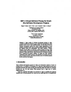
Figure 3. A. GUI panel for the control of scan settings. The numbers of horizontal pixels and vertical lines comprising a single image can be selected independently. The equivalent X and Y galvanometer peak to peak voltages can also be adjusted manually, allowing the laser beam to be “parked” for optical alignment. Single line duration, frame duration and experiment duration are calculated and shown. The degree of optical zoom can be controlled by a slider control or by manual entry of a value. Alternatively, the mouse can be used to define the zoom on the image. The number of images to be averaged can be controlled and the position of the image can be shifted incrementally provided it is smaller than the full frame of 768x512. Regions of interest can be defined over the captured images allowing measurements of fluorescence over time. The red buttons below indicate when a digital output from one of four configured DIOs. Three modes of scanning are supported. Live Scan which simply scans continuously and overwrites consecutive images with the last. In single scan mode, n images are captured and saved and the average is calculated. In series scan mode, n images are captured and the average calculated repetitively at intervals of either every t seconds or z focus position. B. The effects of bath application of 20 mM NH4Cl3 on a PC12 cell transfected with a tandem fluorescent protein consisting of pH sensitive green and yellow fluorescent proteins. The cell was excited with 363nm and 488 nm using UBHS filter block and emission at 514 collected on channel one (green) and 540 on channel 2 (yellow). Data from ROIs placed over a region of background and over the cell were collected online. For presentation, compensation for bleaching was made by fitting the raw data with a single exponential curve and the background subtracted data normalized to baseline (F/F0) and plotted against time.