Field-Detection of Blood Parasites. Stefan H. .... The tracking software was based around available MATLAB code but optimized for this specific task and a GUI ...
Electronic Supplementary Material (ESI) for Analytical Methods. This journal is © The Royal Society of Chemistry 2016 Supplementary Material (ESI) for Analytical Methods This journal is © The Royal Society of Chemistry 2016
Simplifying Microfluidic Separation Devices towards Field-Detection of Blood Parasites Stefan H. Holm, Jason P. Beech, Michael P. Barrett and Jonas O. Tegenfeldt
- Electronic Supplementary Information -
1. Device Design The device consists of three sections, each with parameters optimized to carry out that section’s specific task. Section 1 is deep and has a large critical size in order to sort out WBCs. Section 2 has a lower critical size and is shallow, which maximizes the effective size of the particles making it easy to laterally displace them along the channel walls. Section 3 has the same array parameters as section 2 but the height has been decreased. The height has been optimized to take advantage of the shape difference between erythrocytes and the longer and slender parasites. At the specific height of section 3 (9.0 µm) the parasites will continue to be laterally displaced, this time however towards the centre. The erythrocytes, on the other hand, will appear with a smaller effective size and switch from displacement mode to zig-zag. The parameters of each section can be found in ESI Table 1 below.
ESI Table 1. Device Parameters
Section 1
Section 2
Section 3
22 20 42
12 20 32
12 20 32
row shift, ∆λ (µm) period, N repeats length (µm)
2 21 45 39690
1.2 26.67* 48 40960
1.2 26.67* 48 40960
expected Dc (µm) depth (µm) width (µm)
7.14 26 1890
3.47 3.5 3072
3.47 9.0 3072
7.5∙1012 7.5∙1012
16.6∙1014 8.3∙1014
2.2∙1014 1.1∙1014
gap, G (µm) post diameter, P (µm) post-to-post distance, λ (µm)
resistance per unit cell (Pa∙s∙m-3) total resistance (Pa∙s∙m-3)
* Note that the periodicities in sections 2 and 3 vary within the section. They start with N=26 for one set of rows and then increase to N=27 for the remaining two sets of rows.
Supplementary Material (ESI) for Analytical Methods This journal is © The Royal Society of Chemistry 2016
2. Pressure Response of Syringe Compression The compression of the syringe gives rise to an overpressure driving the sample forward. The resulting overpressure is given by Boyle’s law, i.e. P0V0 = P1V1. Here P0 is the ambient pressure (1 atm) and P1 is the resulting pressure of compressing the air from a volume of V0 to a volume of V1. The pressure difference across a channel with one end at ambient pressure is now simply given by: 𝑉0 Δ𝛲 = 𝛲0 ∙ � − 1� 𝑉1
Conversely, the required compression is easily obtained as a function of the desired pressure difference: 1 V1 = 𝑉0 Δ𝛲 + 1 𝛲0
To increase the pressure stability over time, an additional chamber of 10 mL was added as a dead volume in the system, acting as a pressure reserve to enable measurements over longer times with a consistent flow rate. In addition to this, tubings with a total volume of ~2.5 mL was used, resulting in V0 = 12.5 mL. Depending on the syringe used, different pressures can be achieved in one compression. In ESI Figure 1, the resulting overpressure ∆P=(P1-P0) is plotted as a function of the compression ∆V=(V0-V1). Larger syringes are needed to achieve higher pressure in one compression.
.
Figure 1 Resulting overpressure (left) and throughput (right) by the compression of syringes of various sizes. Here the pressure system without the syringe is approximated to 12.5 mL. Consequently, to reach an overpressure of 1 bar, the syringe need to be of at least this volume
Supplementary Material (ESI) for Analytical Methods This journal is © The Royal Society of Chemistry 2016
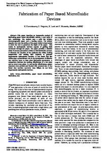
3. Channels of Identical Resistance Connecting Subsequent Sections Due to the low angle of displacement and our device consisting of multiple sections, each with its dedicated task, the entire device will be relatively long (~15 cm). With a goal of fitting the device on a single glass slide (75 x 25 mm) the device was given a folded design, with channels connecting the different section. Here, it was crucial to ensure that the fluidic resistance of all the channels connecting two sections were equal. In order to accomplish this, the widths of the channels were adjusted to compensate for the length differences.
Figure 2 Device overview showing the three different sections together with the connection channels of equal resistance ensuring that particles maintain their relative position in longer microfluidic devices
Supplementary Material (ESI) for Analytical Methods This journal is © The Royal Society of Chemistry 2016
Figure 3 Schematic illustration of the curved channels connecting section 2 and 3, showing how the lengths increases with increasing channel number.
For the channels connecting section 2 and 3, 30 channels were chosen. As can be seen in ESI Figure 3, 𝜋
the channels consist of two identical 2 rad annulus sectors connected via a straight channel. With a
device width of 3072 µm, the centres of the channels will be separated by a distance d = 102.4 µm. The radius of the innermost annulus sector is r = 550 µm. The straight channel is Ls = 1000 µm for the first 15 channel and 1064 µm for the remaining 15. With the hydraulic resistance given by1 −1
∞
(2𝑛 − 1)𝜋𝜋 12𝜂𝜂 ℎ 192 1 𝑅= tanh � �1 − � 5 � ��� 3 5 (2𝑛 − 1) 𝑤ℎ 𝑤 𝜋 2ℎ 𝑛=1
where w,h,L are the dimensions of the channel, and η the viscosity. By setting the width of channel 30 to 50 µm the resistance can be calculated to 4.024∙1016 Pa∙s∙m-3. Thereafter the widths corresponding to this resistance can be calculated for the remaining channels, the result can be found in ESI Table 2. ESI Table 2. Parameters of channels between section 2 and 3
Channel
Ls / µm
r / µm
Ltot / µm
w / µm
1 2 3 4 5 6 7 8 9 10 11 12 13 14 15 16
1064 1064 1064 1064 1064 1064 1064 1064 1064 1064 1064 1064 1064 1064 1064 1000
11057.15 10735.45 10413.75 10092.05 9770.35 9448.65 9126.95 8805.26 8483.56 8161.86 7840.16 7518.46 7196.76 6875.06 6553.36 6231.66
12121.15 11799.45 11477.75 11156.05 10834.35 10512.65 10190.95 9869.26 9547.56 9225.86 8904.16 8582.46 8260.76 7939.06 7617.36 7231.66
50 48.83 47.65 46.47 45.3 44.12 42.94 41.77 40.59 39.41 38.24 37.06 35.88 34.71 33.53 32.12
R / 1016∙ Pa∙s∙m-3 4.0240 4.0238 4.0238 4.0238 4.0238 4.0238 4.0238 4.0238 4.0238 4.0238 4.0238 4.0238 4.0238 4.0238 4.0238 4.0238
Supplementary Material (ESI) for Analytical Methods This journal is © The Royal Society of Chemistry 2016 17 18 19 20 21 22 23 24 25 26 27 28 29 30
1000 1000 1000 1000 1000 1000 1000 1000 1000 1000 1000 1000 1000 1000
5909.96 5588.27 5266.57 4944.87 4623.17 4301.47 3979.77 3658.07 3336.37 3014.67 2692.97 2371.27 2049.58 1727.88
6909.96 6588.27 6266.57 5944.87 5623.17 5301.47 4979.77 4658.07 4336.37 4014.67 3692.97 3371.27 3049.58 2727.88
30.94 29.77 28.59 27.41 26.24 25.06 23.88 22.7 21.53 20.35 19.16 17.98 16.79 15.6
4.0238 4.0238 4.0238 4.0238 4.0238 4.0238 4.0238 4.0238 4.0239 4.0239 4.0239 4.0239 4.0239 4.0239
The connecting channels were validated by the use of COMSOL Multiphysics 5.0 (COMSOL AB, Stockholm, Sweden). ESI Figure 4 shows that there is no lateral flow prior to the particles enter the connecting channels. This ensures that they will retain their lateral position relative to each other between sections.
Figure 4 2D-plot of the curved channels connecting section 2 and 3, simulated by COMSOL. The fluid enters the model from the boundary at y=0. 30 flow streams have been positioned equidistanced along the same border to illustrate that the flow is split up evenly before entering the channels. This ensures that particles will retain their relative lateral position between the different sections.
Supplementary Material (ESI) for Analytical Methods This journal is © The Royal Society of Chemistry 2016
4. Automated Tracking Software
The tracking software was based around available MATLAB code but optimized for this specific task and a GUI was added to easily extract trajectories of several thousands of particles within minutes. More information can be found at http://site.physics.georgetown.edu/matlab/ http://www.physics.emory.edu/faculty/weeks//idl/tracking.html See also ESI_Movie1.mp4
Figure 5 Graphical user interface of the automated tracking sofware used to correctly determine the position of several thousands of particles in order to acquire good statistics
Supplementary Material (ESI) for Analytical Methods This journal is © The Royal Society of Chemistry 2016
Lateral Distribution of Trypanosomes at Various Pressures
Figure 6 Lateral distribution of trypanosomes at the end of the three different sections, measured at various pressures. The percentages refer to the fraction of the trypanosomes entering the section that are deviated to the indicated outlet. At the end of array 1, 20% of the total flow is diverted to the leukocyte outlet. As the leukocytes are spherical and larger, they are expected to become laterally displaced in this section, and consequently, enriched at this side of the device. However, at low flow velocities, and consequently low shear forces, the trypanosomes also behave as larger particles. Thus, they get enriched to some extent as well and more than the expected 20% are lost to the leukocyte outlet. As can be seen, at 100 mBar, 36.5% of the trypanosomes are sorted out to the leukocyte channel. In array 2, the cells are supposed to be laterally displaced towards the channel walls. At high flow velocities the soft cells will be squeezed by the shear stress and consequently behave as smaller particles. In this way they can avoid being displaced towards the side of the channels. At the end of section 3, the trypanosomes are expected to have been focused to the center of the channel while the RBCs should remain focused along the channel walls on the side. As can be seen here, increasing the flow rate will act to decrease the fraction of trypanosomes in the center outlet. This is believed to be a consequence of the increasing shear forces acting to, once again, deform the relatively soft parasites making them able to avoid being laterally displaced.
Supplementary Material (ESI) for Analytical Methods This journal is © The Royal Society of Chemistry 2016
5. Lateral Distribution of Erythrocytes at Various Pressures
Figure 7 Lateral distribution of erythrocytes at the end of the three different sections, measured at various pressures. The percentages refer to the fraction of the erythrocytes entering the section that are deviated to the indicated outlet. Similar to how the trypanosomes behave in Figure 2, the erythrocytes are not laterally displaced to a large extent in section 1. The low depth in section two, also here, act to maximize the effective size of the particles and consequently, with high accuracy, laterally displace the cells towards the channel walls. The most important numbers are given at the end of section 3 as this is the outlet distribution. Here we can see the same numbers as given in Figure 5A. At very low pressures the erythrocytes sediment and are sorted, in this section, according to their diameter, ~7.5 µm, instead of their width 2.5 µm. As a consequence they are laterally displaced, to a larger extent, into the trypanosome outlet. At higher pressures the shear stress exerted on the erythrocytes act to decrease their effective size, making them avoid being laterally displaced. At even higher pressures, this will also happen in section 2 resulting in erythrocytes less focused along the channel walls. Consequently, at these high pressures, a larger amount of erythrocytes exit to the trypanosome outlet. Further, the number of erythrocytes in the trypanosomes outlet are minimal at a pressure of 600 mBar.
Supplementary Material (ESI) for Analytical Methods This journal is © The Royal Society of Chemistry 2016
6. Measurements of Spiked Samples
Figure 8 Lateral distribution of spiked samples measured at 1.9 µl/min. Overall the results are in close agreement with erythrocytes and T. cyclops analysed separately at this pressure (see Figure 6). At the end of section 1 the distribution of both cell types are uniform, as expected, due to the critical size being larger than the particle size. Consequently around 20 % of the cells are sorted out while the remaining fraction continues into section2. In section 2 the majority of the cells are well-focused along the channel walls, opening up a cellfree stream in the centre. In section3, which only differs from section 2 in terms of depth and displacement direction, the trypanosomes are displaced to a large degree with 83.1 % being sorted out into outlet 3, while the erythrocytes mainly zigzag into outlet 2.
Supplementary Material (ESI) for Analytical Methods This journal is © The Royal Society of Chemistry 2016
7. Trypanosome Culturing The parasite T. cyclops was kept in culture flask with Cunningham’s medium supplemented with 20% FCS. The time between splits were kept at around 14 days.
Figure 9 Measured growth curve of T. cyclops using a haemocytometer. After around a week a burst in the density was noted as the population entered their exponential growth phase. After another week the culture entered the lag phase. Culture splitting was carried out around 14 days after last split in order to maintain the parasites healthy.
Culture splitting (every 14 days) • • • • •
Sterilize two culture flasks by autoclaving Sterilize laminar flow hood and gloves with 70% EtOH Fill each culture flask with 15 ml of culture medium Add 4 ml (20%) FCS to the Cunningham’s medium, heat suspension to 28oC Use sterile pipettes to transfer 1 ml of trypanosome suspension to the culture flask
T. cyclops samples • • •
Use exponential-phase trypanosomes, around 7 days since last split. Take from upper half to avoid dead parasites and debris Count the density and dilute to desired concentration using culture medium Pipette 100 µl of trypanosomes into inlet reservoir
Simultaneous Analysis of Erythrocytes and T. cyclops • • •
Count the T. cyclops density using a haemocytometer Create a running buffer containing culture medium with 3mM EDTA and 20% FCS to the desired density Dilute the T. cyclops to desired concentration using the running buffer
Supplementary Material (ESI) for Analytical Methods This journal is © The Royal Society of Chemistry 2016 • • • • •
Aspirate 150 μl of the running buffer in a 200 μl pipette tip Prick finger with Haemedic Haemolance® low flow Aspirate 50 μl of blood with the filled pipette tip into the Eppendorf tube Wash blood sample three times with the running buffer at 1000 g for 1 min, Resuspend pellet with 475 µl (for 10x dilution) of the T. cyclops solution in running buffer
Supplementary Material (ESI) for Analytical Methods This journal is © The Royal Society of Chemistry 2016
8. Movies Showing Sorting of Erythrocytes and Trypanosomes
ESI_Movie2.mp4 The lateral distribution of erythrocytes at the three different sections is presented. In the end of section 1, the erythrocytes are relatively evenly distributed. In section two, the cells are focused along the channel walls in order to open up the cell-free stream in the centre. In the final section 3 the erythrocytes are expected to be minimally displaced in order to achieve the best separation.
Supplementary Material (ESI) for Analytical Methods This journal is © The Royal Society of Chemistry 2016
ESI_Movie3.mp4 The end of section 3 is viewed at a high magnification, to see the individual T. cyclops parasites. At this flow rate (1.9 µl/min - 600 mBar), the parasites are focused to a large extent to the centre of the device, exiting mainly to the parasite outlet. Some of the parasites can however be seen to avoid displacement, most likely due to their smaller size or different shape.
1.
H. Bruus, Theoretical Microfluidics, OUP Oxford, 2008.