Simulating a Multi-Agent based Self-Reconfigurable. Electric Power Distribution System. Janeth G. Gómez-Gualdrón, Student Member, and Miguel Vélez-Reyes, ...
2006 IEEE COMPEL Workshop, Rensselaer Polytechnic Institute, Troy, NY, USA, July 16-19, 2006
Simulating a Multi-Agent based Self-Reconfigurable Electric Power Distribution System Janeth G. Gómez-Gualdrón, Student Member, and Miguel Vélez-Reyes, Senior Member Center for Power Electronic Systems, University of Puerto Rico at Mayagüez, P.O. Box 9048 Mayagüez, PR 00681-9048 E-mail: {janeth.gomez, m.velez}@ieee.org Abstract-- Electric power distribution systems can be found almost everywhere, from ship power systems to data centers. In many critical applications, there is need to maintain minimal operating capability under fault conditions. To carry out this goal it is necessary to develop energy distribution control techniques, which let implement a self-reconfigurable energy distribution system. This research project is looking at the implementation of a Multi-Agent System to develop a self-reconfigurable electric power distribution system. A Simulation Model composes by a Multi-Agent System developed with Java programming language, a simplified EPDS model implemented in SimulinkTM and a communication middleware between them is presented. The communication middleware is an application programming interface to exchange data between SimulinkTM models and MultiAgent Systems implemented in JADE platform using Java. Also, we present advantages and disadvantages of this process.
we are looking at the application of agent systems to implement the distributed intelligence required in selfreconfigurable EPDS. As a sub-field of Distributed Artificial Intelligence, MultiAgent Systems (MAS) are a promising technology to fulfill these requirements. An agent is an abstraction, a logical model that describes software that “acts on behalf of” a user or other program; that software agent has the authority to decide if and when an action is appropriated, also it has the autonomy to activate itself or it can be invoked by a task [1]. Some research works have been dedicated to study the application of Multi-Agent systems to the problems of protection and reconfiguration of AC and DC power systems. In 1998, Tomita, Fukui, Kudo, Koda and Yabe [2] proposed a "relay agent" to build a cooperative protection system. Thorp et al. [3, 4] used geographically distributed agents located in a number of intelligent electronic devices for reconfiguration and developed a simulation platform called EPOCHS. EPOCHS allows agents to operate in a simulation environment that combines electric power, electromagnetic and electromechanical transient simulators with a network communication simulation engine. Recent works in the field are starting to use international standards for Multi-Agent Systems to develop their systems and to implement communication and negotiation strategies. Sun and Cartes [5] are working in the reconfiguration of a shipboard power system using agents to represent and to control critical system components. Wang, et al. [6] proposed a MAS for power restoration using priorities. Maturana et al. [7] proposed an Agent-based Control system to provide intelligent control on capital ships. We proposed in [8] a prototype of a Multi-Agent system to reconfigure the system in order to maximize the number of served loads with highest priority. Developing interfaces between electric models and software agents is a key element in the works described previously. In [3, 4], Thorp et al. describe the Electric Power and Communication Synchronizing Simulator (EPOCHS); EPOCHS is a simulation system, which links the electromagnetic and electromechanical transient simulators with an event-driven communication network simulator. Another implementation to integrate software agents with simulation electrical models is presented in [9]; there CORBA is used to communicate a the MAS with a EPDS model in
I. INTRODUCTION Today's complex electric power distribution systems (EPDS) in data centers, automotive, ships and aircrafts require sophisticated control techniques to support all aspects of operation including failures. When a high degree of reliability is desired, the effects of failures must be mitigated and control must be maintained at survivable scenarios. In order to manage fault scenarios, we need to make a series of decisions and control actions: 1. The fault has to be detected 2. The fault source has to be identified and its magnitude estimated (partial degradation vs. total failure) 3. Depending on the nature of the failure, actions have to be taken that compensate for the failure: A new network topology is chosen The EPDS has to be reconfigured. All these decisions must be made by a self-reconfigurable control system that incorporates not only simple regulatory loops and the supervisory control logic, but also a set of components that detect, isolate, and manage faults, in coordination with the control functions. In fact, it is envisioned that in the future, the EPDS will have the intelligence for rapid self-reconfiguration under fault scenarios. In order to achieve these goals, traditional centralized control is being replaced for intelligent distributed controllers across the Electric Power Distribution Network. In our work, 0-7803-9724-X/06/$20.00 ©2006 ©2006 IEEE. 0-7803-9725-8/06/$20.00 IEEE.
1
Virtual Test Bed (VTB) simulation environment. It is essential to emphasize the importance of the communication between different technologies because it allows us to use the appropriate language for each part of the system. The Distributed Heterogeneous Simulation Project [10] at Purdue University is looking for the integration of different platforms, programming languages, and simulation approaches. In our work, we are focused in the integration of two technologies, SimulinkTM and the JADE environment in Java. This paper presents our initial results in implementing a Simulation Model composed by a Multi-Agent System developed in the Java programming language and a simple EPDS model implemented in SimulinkTM. We pay special attention in this paper to the communication middleware between them. The communication middleware allows the MAS to send/receive data to/from the EPDS Simulink TM model. We will present a brief explanation of each one of the components needed for this communication with their functionality in the process. In addition, we discuss the advantages and disadvantages of this approach. II. MULTI-AGENT SYSTEMS Multi-Agent Systems (MAS) are one of the most interesting new sub-fields of Computer Science and Distributed Artificial Intelligence. They have been studied since 1980, but the interest on them has grown rapidly after mid-1990s. MAS are composed of multiple interacting computing elements, known as agents. Although a general description of an agent was given in the previous section, there is no universally accepted definition of what an agent is. However there is an agreement on their general characteristics [13]: 1. Autonomy: An agent is autonomous when it operates without the direct intervention of humans or other agents, if it can decide for itself what it needs to do in order to achieve its objectives. 2. Social ability: An agent must be in capacity to cooperate, coordinate and negotiate with other agents using a communication language. 3. Reactivity: An agent perceives its environment and responds in a timely fashion to changes that occur in it. A reactive agent presents behaviors stimuli-answer. 4. Proactiveness: It is the capacity to exhibit a goal-directed behavior by taking the initiative. The agents contained in Multi-Agent environments are autonomous and distributed, and they can be self-interested or cooperative. These kinds of environments have no single designer and they provide an infrastructure for specifying communication and interaction protocols [14]. The aspects related with agent technology and MAS are standardized by The Foundation for Intelligent Physical Agents (FIPA) [15].
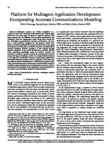
Fig. 1. Simulation model used in the study.
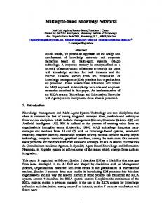
III. SIMULATION MODEL The implemented simulation model is composed of three components. The first is the SimulinkTM implementation of the electric power distribution system (EPDS). The second part is the multi-agent system implemented in the Java Agent DEvelopment Framework (JADE) [16]. The third component is the communication between the two processes. A. Electric Power Distribution System The EPDS used in this study was motivated by the DC Zonal Electric Distribution System (DCZEDS) shown in Fig. 2 [11, 12]. The DCZEDS is part of the Integrated Power System architecture proposed by the Advanced Surface Machinery Program of the NAVY Naval Sea Systems Command, the power distribution is based on the zonal distribution architecture, which includes both AC backbone, and DC zonal systems. This system is proposed as the challenge system in the NSF/ONR EPNES program [11]. A MATLAB implementation of the model was provided to the grantees. Zonal architectures have several advantages over traditional ring bus distribution systems supplying radial feeders, including better reconfigurability and greater survivability. A simple circuit of a single bus feeding three loads emulating the the upper half of the DCZEDS was used in our initial simulation work as the power distribution network to reconfigure under fault conditions and it is shown in Fig. 3. In the EPDS of Fig. 3, the ship service converter modules
2
in JADE and the SimulinkTM model of the EPDS. During simulation time, a communication channel is established between the SimulinkTM model and ServerAgent. When the ServerAgent detects a change in system conditions, it sends this information to the ZoneAgent; who negotiates with its neighboring ZoneAgents to reconfigure the system. Each ZoneAgent only negotiates with its immediate neighbors, reducing the dependency between the algorithm and system topology. The interaction between agents is based on the specifications provided by the Foundation for Intelligent Physical Agents (FIPA) such as Agent Communication Language (ACL) [17] and Contract Net interaction protocol [18, 19].
(SSCM) are represented by switches that connect the loads to the main bus and tie switches are used to provide further reconfigurability capability to the system. We impose a constraint that the SSCM switches can only support 1.5 loads so you need at least two active SSCM to feed all three loads to model limited power processing capacity for the power converters.
C. Communication Middleware In order to exchange information between the DCZEDS model in SimulinkTM and the MAS in JADE, it is necessary to use a middleware to communicate them. The MAS needs to know when faults occur in the power system to take the needed control actions to reconfigure the system which must be applied to the SimulinkTM model. IV. JADE-SIMULINKTM INTEGRATION
Fig. 2 ONR Reference System: NAVY proposed IPS Architecture.
In this section, we describe the implementation of the communication middleware used in the Simulation Model. The communication middleware allows the JADE MAS to send/receive data to/from the EPDS SimulinkTM model. The top part of Fig. 1 shows the SimulinkTM implementation of the simplified DCZEDS. The SimulinkTM model includes an embedded MATLAB function block for each Zone which is used to send/receive information to/from the JADE MAS. Although MATLAB has functions that support JAVA [21] the embedded MATLAB functions in SimulinkTM do not. Therefore we could not directly communicate the EPDS SimulinkTM model with the reconfiguration agents in JADE. The alternative followed here was to implement the middleware using TCP sockets. A socket is one endpoint of a two-way communication link between two programs running on the network and it is bound to a port number [22]. A socket can perform seven basic operations [23]: Connect to a remote machine Send data Receive data Close a connection Bind to a port Listen for incoming data Accept connections from remote machines on the bound port To use sockets, it is necessary to have a Server and a Client. In our Simulation Model, the Client is the model running in SimulinkTM and the Server is the JADE Multi-Agent System.
Fig. 3. Simplified DCZEDS used in the initial simulation studies.
During faults, loads are kept online according to a priority. Load 1 has the highest priority and Load 3 has the lowest. The reconfiguration agents were designed using these constraints and priorities. Only faults on the SSCM are considered at this point. All loads are simple identical RC circuits. Our objective in this work was to focus on topological reconfigurability and in the communication aspects between SIMULINK and the MAS development software platform, JADE. B. Multi-Agent System The Multi-Agent System is implemented using the platform Java Agent DEvelopment Framework (JADE) [16], which is a JAVA framework for developing FIPA-compliant agent applications. In addition, JADE provides tools to facilitate the debugging process and to track the actions of the agents. The JADE MAS (lower part of Fig. 1) is composed by two agents for each zone, ZoneAgent and ServerAgent. The ZoneAgent is the reconfiguration agent for the zone and the ServerAgent manages the communication between ZoneAgent
A. Server Socket As a Server Socket, a new Agent called ServerAgent is
3
writing to or reading from their sockets as shown in Fig. 5.
introduced. ServerAgent is an agent that has the function to communicate with remote clients via a socket. When the ServerAgent is launched, it searches for a file with the initialization parameters such as the name and the port number to which it listens for connections. Each message that arrives through the socket is analyzed and if the conditions of the system have changed, the message is forwarded to the ZoneAgent. Each control action from the ZoneAgent is forwarded back to the SimulinkTM model through the ServerAgent. B. Client Socket To open a Client Socket in SimulinkTM, MATLAB code implemented in an embedded MATLAB function within SimulinkTM is used. We used the “TCP/UDP/IP Toolbox” developed by Peter Rydesäter [24] to implement the client socket. This toolbox allows a MATLAB program to set up TCP/IP connections in MATLAB and to transmit data over a socket between MATLAB processes or other applications. It is possible to act as server and/or client and transmit textstrings, arrays of any datatype, files or MATLAB variables.
Fig. 4. Request a connection to the ServerAgent.
C. Client/Server Operation Fig. 4 shows the process of requesting a connection. When the Multi-Agent System starts, the ServerAgent of each zone is listening to a specific port number and it waits for the client (in this case the client is the “Embedded MATLAB function” of the zone) to make a connection request. The command used to create a Server Socket is:
Fig. 5. Client/Server Connection Established.
The commands used to send/receive information to/from the ServerAgent’s are: - Send Information:
ServerSocket listen_socket = new ServerSocket(port);
When the embedded MATLAB function in the SimulinkTM Model asks for a connection, the ServerAgent must accept it. The commands used in the ServerAgent to accept and to establish input and output streams are:
string = num2str(time); pnet(con, ȇprintfȇ, string, ȇnoblockȇ);
- Receive Information: str = pnet(con, ȇreadlineȇ, ȇnoblockȇ); C12 = str2double(str);
Socket client_socket = listen_socket.accept();
In both cases, the parameter “noblock” allows the simulation to continue even if the answer of the MAS has not been sent; this is because in a real operation the EPDS will continue with or without the answer of the controller. The commands used in the ServerAgent to send/receive information to/from the Zone in the SimulinkTM Model are: - Send Information:
BufferedReader in = new BufferedReader (new InputStreamReader(client_socket.getInputStream())); PrintStream out = new PrintStream(client_socket.getOutputStream(), true);
On the client-side (Model in SimulinkTM), the client knows the hostname of the machine on which the ServerAgent is running and its port number. As shown in Fig. 4, at the beginning of the simulation, a connection to the ServerAgent is created using the function PNET from TCP/UDP/IP Toolbox with the following command:
out.println(ȈcontrolȈ); out.flush();
- Receive Information: double time = Double.parseDouble(in.readLine());
D. Synchronization problems In our first implementations, the MAS received the information of voltage and current, processed them and sent an answer without considering the SimulinkTM local simulation time in which the message was received and processed. SimulinkTM integration routines iterate in runtime when conditions such as faults or reconfiguration that create jump changes in the network structure and goes back in the
if (isempty(con)) con = pnet(ȇtcpconnectȇ, ȇlocalhostȇ, 4096); end
The ServerAgent accepts the connection. On the client side, when the connection is accepted, a socket is successfully created and the client can use the socket to communicate with the server. The client and server can now communicate by
4
representation of its zone, the ZoneAgent3 sends a call for proposals (CFP) message to its neighbor ZoneAgent2. ZoneAgent2 checks the available resources of its zone, but they are not enough to feed both zones. ZoneAgent2 needs to obtain the other part of the power requested by ZoneAgent3, for that reason, it sends a “CFP” to its neighbor ZoneAgent1 and the negotiation process happens according to Contract Net Protocol. When ZoneAgent2 has the proposal of ZoneAgent1 and its power available, it sends a proposal to ZoneAgent3, and the negotiation process occurs according to Contract Net Protocol. When the proposal of ZoneAgent2 is accepted it must inform to ZoneAgent1 using a “confirm” message. “CFP” are sent to each neighbor ZoneAgent, in this case, there is only one neighbor, but, if the agent has more than one neighbor ZoneAgent could receive more than one proposal, so they are evaluated to find the lowest cost with the greatest amount of load served. The cost of each proposal is the costpath between the Zone Client and the Zone(s) Helper(s); the cost-path is the sum of the cost of all edges that form the path. At t=3.5 sec., when the fault in Zone 2 occurs, the ServerAgent2 sends a “request” to ZoneAgent2 to inform the agent about the fault. ZoneAgent2 sends a “CFP” to its neighbors, but no one can help Zone 2. ZoneAgent1 only can feed its own load, so it opens the tie switch with its neighbor Zone 2. At t=5.5 sec. when the fault in the SSCM of Zone 3 is cleared, ZoneAgent3 informs to its neighbor ZoneAgent2 about this change; then a negotiation process between ZoneAgent’s starts in order to reconfigure the system to feed the three loads. At t=6.5 sec. the system returns to its initial no-faults state when the fault in the SSCM of Zone 2 is cleared, the zones release the resources with a “cancel” message and the tie switches between the zones are opened again. After a negotiation process each ZoneAgent establishes the control signals and they are sent to its ServerAgent, who transmits them to the SimulinkTM model. Fig. 7 shows the control signals for each zone; they are sent from ZoneAgents to ServerAgents. Each ServerAgent sends the signals through the socket and they are received by the client socket in the SimulinkTM model of each zone. The figure shows the expected behavior based on the described fault conditions. In each Zone, the last control signal is used to connect or to disconnect the load and the other signals are used to control the connection with its neighbor zones. Each zone must send a control signal. Fig. 8(a) and 8(b) show the voltage and current waveforms. They show how the MAS acts; it reconfigures the system when fault and recovery conditions occur. When the fault occurred in Zone 3, the voltage was affected because of the simulated communication delay of the control signals and the response time of the MAS, but the reconfiguration process allows the systems to feed the three loads.
simulation time to use a smaller step size to increase its accuracy under these conditions so when the MAS receives the information in an specified time, the control actions were applied in the SimulinkTM simulation time at time earlier than the time when the fault occured. To solve this synchronization problem, the value of time of the SimulinkTM simulation is sent to the ServerAgent. Before the ServerAgent sends the control action, it verifies that the local simulation time is later than the time of the fault. If(currentTime>requestTime) sendAnswer();
V. SIMULATION RESULTS In order to test the operation of the System and to evaluate its performance, different fault scenarios were simulated and evaluated and described in [8]. One of the simulated cases is presented here A. Case: Two Faults Contingency 1) Simulation Parameters Duration of Simulation: 10 seconds. At the beginning of the simulation the system is in normal state (no faults). At t=1.5 seconds, a fault takes place in the SSCM that feeds Zone 3. The MAS must respond to this event and to reconfigure the system, so the load of Zone 3 is fed using the tie switches, for this it is necessary to close the tie switches between all zones. At t=3.5 seconds, a fault takes place in the connection that feeds Zone 2. At this moment, the system can feed only one Zone, so the highest priority Zone 1 is fed from the SSCM of its Zone. The switches between the zones are opened. At t=5.5 seconds, the fault in the SSCM of Zone 3 is cleared. The system can feed the three loads again. The load of Zone 2 is fed using the tie switches, so the switches between all zones are closed. At t=6.5 seconds, the fault in the SSCM of Zone 2 is cleared and the system is restored to its initial no-faults state. 2) Negotiation Process. Fig. 6 shows the Sniffer Agent GUI. The Sniffer Agent is a tool provided by JADE and it is a FIPA-compliant Agent, which is used to track the message exchange between agents [16]. When the system starts, each connection between the zones in the SimulinkTM model and their ServerAgents in the MAS is open, in this moment each ServerAgent sends a “subscribe” message to its ZoneAgent. During the time of the simulation the client socket in the SimulinkTM Model sends the information about voltage and current to the ServerAgent, when this detects a change in the conditions of the system (fault or recovery) sends a “request” message to ZoneAgent with the related information. When the fault in Zone 3 occurs at t=1.5 sec., the corresponding ServerAgent sends a “request” message to its ZoneAgent in order to inform the agent about the fault. In
5
.
Fig. 6. Case 2: Sniffer Agent GUI - Negotiation Process.
information to the Multi-Agent System. Also a more realistic model for the DCZEDS.
VI. CONCLUSIONS AND FUTURE WORK This paper presents initial results of our work in implementing a simulation model that integrates and EPDS model in SimulinkTM and agents in the JADE environment. This will be used to support our research in using multi-agents to develop self-reconfigurable power distribution systems. Limitations in the SimulinkTM platform required the use of sockets to implement the communication between MATLAB and JADE. Through the experiments we found some synchronization problems between SimulinkTM and Java due to time back stepping in the integration routines used in SimulinkTM. Our simulation results results show the potential of using a MAS approach to implement a self-reconfigurable EPDS and the need for having an efficient communication layer for the simulation model. Future work will look at improving the simulation process and the communication interface between SimulinkTM and Java; to achieve this goal we will include capabilities to send/receive more data types and to make a preliminary process to the data in order to send only relevant
VII. ACKNOWLEDGEMENTS This work was primarily supported by the National Science Foundation under grant ECS-0224743. This work made use of ERC shared facilities supported by the National Science Foundation under Award Number EEC-9731677. VIII. REFERENCES [1] [2]
[3]
[4]
6
“Software agent”, Wikipedia, the free encyclopedia. http://en.wikipedia.org/wiki/Software_agent/ Y. Tomita, C. Fukui, H. Kudo, J. Koda, K. Yabe, "A Cooperative Protection System with an Agent Model". IEEE Transactions on Power Delivery, Vol. 13, no. 4, pp. 1060–1066, Oct. 1998. J.S. Thorp; X.R. Wang; K.M. Hopkinson; D. Coury; R. Giovanini, “Agent Technology Applied to the Protection of Power Systems”, Autonomous Systems and Intelligent Agents in Power System Control and Operation. C. Rehtanz. S. Baden, Eds., Springer-Verlag. 2003. K.M. Hopkinson; K.P. Birman; R. Giovanini; D.V. Coury; X. Wang; J.S. Thorp, “EPOCHS: Integrated Commercial Off-The-Shelf Software for Agent-based Electric Power and Communication Simulation”. Proc. of the 2003 Winter Simulation Conference. 7-10 of December 2003, New Orleans, USA.
[5]
L. Sun and D. Cartes. "A Multi-Agent System for Reconfiguration of Shipboard Power Systems". IASME Transactions. Issue 3, Volume 1, July 2004. [6] H. Wang, N. Schulz, D. Cartes, L. Sun and S. Srivastava "System Reconfiguration Strategy for Shipboard Power Systems Using MultiAgent Systems". ASNE Reconfiguration and Survivability Symposium 2005. Atlantic Beach, Florida. February, 2005. [7] F. Maturana, R. Staron, F. Discenzo, D. Scheidt, M. Pekala, J. Bracy and M. Zink "An Interoperable Agent-based Control System for Survivable Shipboard Automation". ASNE Reconfiguration and Survivability Symposium 2005. Atlantic Beach, Florida. February, 2005. [8] J. Gomez-Gualdron and M. Velez-Reyes. A Multi-Agent approach for a Self-Reconfigurable electronic Power Distribution System. In Intelligent Computing: Theory and Applications IV. Proceedings of SPIE, Vol. , 2006. [9] G. Morejon, L. Sun, D. Cartes. CORBA Implementation for Interfacing Software Agents with Virtual Test Bed. ASNE Reconfiguration and Survivability Symposium 2005. Atlantic Beach, Florida. February, 2005. [10] Distributed Heterogeneous Simulation (DHS) Project. Center for the Security of Large Scale Systems (CSLSS) at Purdue University. http://center.e-enterprise.purdue.edu/wps/portal/.cmd/cs/.ce/155/.s/4913 [11] ONR Control Challenge Problem. http://www.usna.edu/EPNES [12] Sudhoff, S.D.; Pekarek, S.; Kuhn, B.; Glover, S.; Sauer, J.; Delisle, D. “Naval combat survivability testbeds for investigation of issues in shipboard power electronics based power and propulsion systems” In Proceedings of the 2002 Power Engineering Society Summer Meeting, Volume: 1 , 21-25 July 2002. Page(s): 347 -350 vol.1. [13] M. Wooldridge “An Introduction to Multi-Agent Systems”. John Wiley and Sons. England, 2002. [14] G. Weiss (ed.), “Multi-Agent Systems. A Modern Approach to Distributed Artificial Intelligence”, The MIT Press, Cambridge, MA, 1999. [15] The Foundation for Intelligent Physical Agents. 2005. http://www.fipa.org. [16] Telecom Italia Lab. JADE (Java Agent DEvelopment Framework). http://jade.tilab.com/ [17] FIPA ACL Message Structure Specification. 2002. Foundation for Intelligent Physical Agents. http://www.fipa.org/specs/fipa00061/. [18] FIPA Contract Net Interaction Protocol Specification. 2002. Foundation for Intelligent Physical Agents. http://www.fipa.org/specs/fipa00029. [19] R.G. Smith, “The Contract Net Protocol: High-level Communication and Control in a Distributed Problem Solver.” In IEEE Transactions on Computers, 1980. [20] The MathWorks. MATLAB – Simulink Documentation. http://www.mathworks.com/access/helpdesk/help/toolbox/simulink/ [21] The MathWorks. “MATLAB Documentation, External Interfaces”.
Fig. 7. Case 2: Time Diagram of Control Signals.
Fig. 8. Case 2: Zone Voltages and Currents.
http://www.mathworks.com/access/helpdesk/help/techdoc/matlab_external/
[22] Sun Microsystems, Inc. "The JavaTM Tutorial". http://java.sun.com/docs/books/tutorial/ [23] E. Rusty Harold. Java Network Programming, Second Edition. O’reilly 2000. [24] MATLAB Central File Exchange - TCP/UDP/IP Toolbox 2.0.5 http://www.mathworks.com/matlabcentral/fileexchange/loadFile.do?obje ctId=345&objectType=file
7