Email: {chmehl, mwrulich, jcolom, dbosanska, mrupp}@nt.tuwien.ac.at ... the source code of all functions is also provided, highest flexibility for changes and additions as well as ..... generators to a predefined state at the beginning of the simulation. ..... Available: http://www.ist-winner.org/phase 2 model.html. [60] C. Studer, M.
17th European Signal Processing Conference (EUSIPCO 2009)
Glasgow, Scotland, August 24-28, 2009
SIMULATING THE LONG TERM EVOLUTION PHYSICAL LAYER Christian Mehlf¨ uhrer, Martin Wrulich, Josep Colom Ikuno, Dagmar Bosanska, Markus Rupp Institute of Communications and Radio-Frequency Engineering Vienna University of Technology Gusshausstrasse 25/389, A-1040 Vienna, Austria Email: {chmehl, mwrulich, jcolom, dbosanska, mrupp}@nt.tuwien.ac.at Web: http://www.nt.tuwien.ac.at/ltesimulator
ABSTRACT Research and development of signal processing algorithms for UMTS Long Term Evolution (LTE) requires a realistic, flexible, and standard-compliant simulation environment. To facilitate comparisons with work of other research groups such a simulation environment should ideally be publicly available. In this paper, we present a MATLAB-based downlink physical-layer simulator for LTE. We identify different research applications that are covered by our simulator. Depending on the research focus, the simulator offers to carry out single-downlink, single-cell multi-user, and multi-cell multi-user simulations. By utilizing the Parallel Computing Toolbox of MATLAB, the simulator can efficiently be executed on multi-core processors to significantly reduce the simulation time. 1. INTRODUCTION In Release 8, Long Term Evolution (LTE) [2] was standardized by 3GPP as the successor of the Universal Mobile Telecommunication System (UMTS). The targets for downlink and uplink peak data rate requirements were set to 100 Mbit/s and 50 Mbit/s, respectively, when operating in a 20 MHz spectrum allocation [3]. First performance evaluations show that the throughput of the LTE physical layer and MIMO enhanced WCDMA [4] is approximately the same [5–9]. However, LTE has several other benefits of which the most important are explained in the following. The LTE downlink transmission scheme is based on Orthogonal Frequency Division Multiple Access (OFDMA) which converts the wide-band frequency selective channel into a set of many flat fading subchannels. The flat fading subchannels have the advantage that—even in the case of MIMO transmission— optimum receivers can be implemented with reasonable complexity, in contrast to WCDMA systems. OFDMA additionally allows for frequency domain scheduling, typically trying to assign only “good” subchannels to the individual users. This offers large throughput gains in the downlink due to multi-user diversity [10, 11]. Another feature of LTE is the X2-interface between basestations. This interface can be used for interference management aiming at decreasing inter-cell interference. The standard only defines the messages exchanged between the base-stations while the algorithms and the exact implementation of the interference mitigation remain vendor specific and are currently a hot topic in research, see for example [12–14].
© EURASIP, 2009
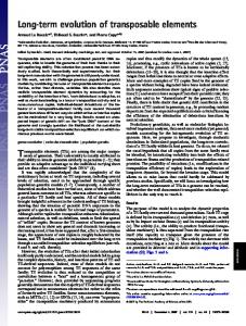
Realistic performance evaluations of LTE require standard compliant simulators. For that reason, commercially available simulators have been developed, for example [15–17]. Also, probably all of the large mobile communication equipment vendors have implemented their own proprietary simulators. However, only a few universities (for example [18]) have done so, due to cost and implementation effort reasons. The simulator of [18] is based on the C++ WM-SIM platform which potentially offers better performance but less flexibility than a Matlab implementation. Unfortunately, the source code of this simulator is not publicly available since it was developed in an academic-industrial cooperation. To the best of the authors’ knowledge, no free opensource LTE simulator is available up to now. In this paper, we present a Matlab-based [19] LTE physical layer simulator and investigate the gains in execution time when parallelizing the simulation. The simulator currently (May 2009) implements a standard compliant LTE downlink with its main features being Adaptive Modulation and Coding (AMC), MIMO transmission, multiple users, and scheduling. It is available [1] for free under an academic, non-commercial use license and allows researchers to compare algorithms in a standardized system. Most parts of the LTE simulator are written in plain Matlab-code. Only computationally intensive functions like soft-sphere or channel decoding are implemented in ANSI-C as MEX functions. Since the source code of all functions is also provided, highest flexibility for changes and additions as well as support for different platforms is guaranteed. This paper is structured as follows: in Section 2 we describe several simulation scenarios that are covered by the LTE simulator. The structure of the simulator is described in detail in Section 3. Section 4 explains the parallel processing utilized. Physical layer simulation results are presented in Section 5. 2. POSSIBLE APPLICATIONS IN RESEARCH In this section, we elaborate on possible applications of the LTE simulator in research. Depending on the application we distinguish between three different classes of simulations that differ greatly in computational complexity, as shown in Figure 1. Furthermore, the simulation code can be utilized to perform real-world measurements with a testbed [20].
1471
LTE TX
Multi-Cell Multi-User
signaling
eNodeB output
channel
delay
...
interference
channel outputs
LTE RX
X2
UE output
Single-Downlink
Figure 2: Overall simulator structure. 2.3 Multi-Cell Multi-User
Single-Cell Multi-User
Figure 1: Overview of different possible simulation scenarios in the LTE simulator.
2.1 Single-Downlink The single-downlink simulation only covers the link between one base-station and one user-equipment. Such a set-up allows for the investigation of • channel estimators, • channel tracking, • channel prediction, • synchronization algorithms, for example [21, 22], • MIMO gains, • AMC feedback including feedback mapping optimization, for example [23], • receiver structures [24], neglecting interference and impact of the scheduling1 , • modeling of channel encoding and decoding [25], and • physical layer modeling [26, 27] crucial for system level simulations. All these simulations require standard compliant implementations of channel coding, MIMO-schemes, transmit signal generation (including pilot and synchronization sequences), as well as channel modeling. 2.2 Single-Cell Multi-User The single-cell multi-user simulation covers the links between one base-station and multiple users. This set-up now additionally allows for the investigation of • receiver structures, taking the influence of the scheduling into account, • multi-user precoding [28], • resource allocation and scheduling, and • multi-user gains. Supplementary to the requirements of the singledownlink scenario, these simulations need a fully functional AMC. In case of receiver structure investigations, the computational complexity of the simulation can be reduced by only evaluating the user of interest. For all other users only the AMC feedback has to be calculated to enable a functional scheduler. 1 Note
that the scheduler in a multi-user system will change the statistics of the individual user’s channel, thus influencing the receiver performance.
The multi-cell multi-user simulation is by far the most computationally demanding scenario and covers the links between multiple base-stations and multiple users. This set-up allows for the realistic investigation of • interference-aware receiver techniques [29, 30], • interference management, including cooperative transmissions [31], and • network based algorithms like joint resource allocation and scheduling. Note that the last two proposed investigations require vast amounts of computational effort. This effort can be greatly reduced by employing system-level simulators [32, 33] in which the physical layer is described by an analytic model. For validation reasons, however, it is still necessary to compare system-level to link-level simulation results. 2.4 Testbed Measurements The LTE simulator can also be used to provide the signal processing part for a testbed [34–37]. Therefore, in the LTE simulator the transmitter and receiver sub-functions are clearly separated required for realworld measurements utilizing physically separated testbed transmitters and receivers. Such measurements have been previously performed at our institute for WiMAX [20, 38] and HSDPA [39, 40] systems. Since in measurements timing and frequency have to be synchronized and the channel has to be estimated, a proper implementation of synchronization and pilot channels is also required. Whereas single-downlink simulations can directly be repeated in measurements, it is very difficult for single-cell multi-user scenarios and even more difficult for multi-cell multi-user scenarios. Testbed measurements also inherently offer another desirable degree of realism. The impact of RF impairments on the LTE link performance can be investigated easily for different components. In simulations, such an analysis would require a very detailed RF modeling, like in [41]. 3. SIMULATOR STRUCTURE 3.1 Overall Simulator Structure The LTE link level simulator consists of the following functional parts: one transmitting eNodeB, N receiver User Equipments (UEs), a downlink channel model over which only the Downlink Shared Channel (DL-SCH) is
1472
user feedback
received signal
signaling
LTE TX scheduler
channel coding of user data bits coding params
user 1
user 2
...
resource block grid
user i
channel estimation
user mapping resource block assignment
LTE RX user i
MIMO TX and OFDM mapping TX signal
resource block disassembling
MIMO RX and OFDM demapping
signaling
channel decoding user feedback
Figure 3: Structure of the LTE transmitter. transmitted, signaling information, and an error-free uplink feedback channel with adjustable delay. The elements of the simulator are shown in Figure 2. 3.2 Transmitter The structure of the transmitter is depicted in Figure 3. As already mentioned in the introduction, LTE downlink transmission is based on OFDMA. The LTE downlink physical resources can thus be represented by a time-frequency resource grid in which each resource element corresponds to one OFDM subcarrier during one OFDM symbol interval. These resource elements are grouped into Resource Blocks (RBs) that consist of six to seven OFDM symbols (depending on the cyclic prefix length utilized) and twelve consecutive subcarriers corresponding to a nominal resource block bandwidth of 180 kHz. This allows for a very flexible resource allocation in a multi-user scenario. In the first step of the transmitter processing, the user data is generated depending on the previous Acknowledgement (ACK) signal. If the previous user data Transport Block (TB) was not acknowledged, the stored TB is retransmitted using a Hybrid Automatic Repeat reQuest (HARQ) scheme. Then a Cyclic Redundancy Check (CRC) is calculated and appended to each user’s TB. The data of each user is independently encoded using a turbo encoder with Quadrature Permutation Polynomial (QPP)-based interleaving [42]. Each block of coded bits is then interleaved and rate-matched with a target rate depending on the received Channel Quality Indicator (CQI) user feedback. Similarly to HSDPA, the rate-matching process in LTE already includes the HARQ process. Due to the high data rates involved, the structure of the turbo encoding and rate matching is slightly different in LTE to ease parallelization [43]. The turbo encoder implementation in our simulator utilizes the convolutional encoder from [44], available under the GNU Lesser General Public License [45]. The CRC is calculated by code generated with [46], available under the Massachusetts Institute of Technology license [47]. Time-intensive operations such as loops and code which was difficult to vectorize are implemented in C via MEX functions [48], including bit interleaving, convolutional encoding/decoding, rate matching, and symbol demapping. The encoding process is followed by the data modulation, which maps the channel-encoded TB to complex modulation symbols. Depending on the CQI, a modulation scheme is selected for the corresponding RB. Possible modulations for the DL-SCH are 4-QAM, 16-QAM,
decoded data bits
BER BLER
throughput
Figure 4: Structure of the LTE receiver. and 64-QAM. The modulated transmit symbols are then mapped to up to four transmit antennas. This antenna mapping depends on the Rank Indicator (RI) feedback and provides different multi-antenna schemes: transmit diversity (TxD), Open Loop Spatial Multiplexing (OLSM), and Closed Loop Spatial Multiplexing (CLSM). In addition, a pre-coding matrix is applied to the transmit signal. The optimum precoding matrix is selected from a code book depending on the Pre-coding Control Information (PCI) that is fed back from the UE to the transmitter. Finally, the individual symbols to be transmitted on each antenna are mapped to the resource elements. Downlink reference symbols and synchronization symbols are also inserted into the OFDM time-frequency grid. The assignment of a set of RBs to UEs is carried out by the scheduler based on the CQI reports from the UEs. The downlink scheduling is carried out on a subframe basis with a subframe duration of 1 ms. Currently, the scheduling is based either on a static resource block assignment matrix or a simple Round Robin scheduler. More realistic, dynamic schedulers will be implemented in the future. 3.3 Channel Model For comparison purposes, the frequency-selective channels are modeled by the ITU [49] and 3GPP [50] Power Delay Profiles (PDPs). Time-variant fading is generated using a sum-of-sinusoids statistical simulation model [51]. Due to the large operating bandwidths of LTE, the standard ITU models show an apparent periodicity in their frequency response. Hence, we also implemented extended versions of the ITU-R models [52], which add more taps to the channel model while keeping the same mean delay and almost the same RMS delay spread. In order to resample the channel impulse response to the required sampling frequency for each LTE bandwidth, sinc-interpolation has been used [53–55]. Ongoing work involves the integration of the 3GPP Spatial Channel Model (SCM) [56, 57], the SCM Extended (SCME) [58], and the WINNER channel model [59] into the LTE link level simulator. 3.4 Receiver The receiver structure is shown in Figure 4. Each UE receives the signal transmitted by the eNodeB and per-
1473
Basic Features Multi-user HARQ
forms the reverse physical-layer processing of the transmitter. First, the receiver has to identify the RBs that carry its designated information. The estimation of the channel is performed using the reference signals available in the resource grid. Based on this channel estimation, the quality of the channel may be evaluated and the appropriate feedback information calculated. The channel knowledge is also used for the demodulation and soft-demapping of the OFDM signal. In case of MIMO, a C implementation of a soft-output sphere decoder with a single tree search [60] is used. Finally, the UE performs HARQ combining and channel decoding. In order to cut down processing time, at every turbo iteration a CRC check of the decoded block is performed and if correct, decoding is stopped. The impact of the additional CRC checks is negligible, as a turbo decoder iteration requires a computation time three orders of magnitude bigger than the CRC check. After each evaluation, the receiver provides the information necessary to evaluate the figures of merit, including user and cell throughput, Bit Error Ratio (BER), and Block Error Ratio (BLER).
AMC CQI feedback MIMO Modes Transmit diversity OLSM CLSM Scheduling Round Robin Proportional fair Best CQI Channel Models AWGN Flat Rayleigh Block fading Fast fading [51] ITU-R models [49, 52]
3.5 Implementation Status The current (Version 1.0r400, May 2009) implementation status of the LTE physical layer simulator is summarized in Table 1. In the near future, the main focus will lie on the implementation of the channel adaptation, especially the calculation of the CQI, the PCI, and the RI at the receiver. The simulator, however, is already prepared for channel-adaptive simulations, that is, the feedback channel as well as all MIMO schemes are fully implemented; only methods for calculating the feedback are missing. 4. EXPLOITING PARALLELISM Modern communication systems become more and more complex and consequently also simulation time of such systems increases. This holds in particular for LTE due to its design towards multi-user support. Accordingly, not only the scheduler but also the physical layer processing of multiple users have to be simulated, thus significantly increasing the computational burden. This can partly be compensated by the faster processors in new computers. However, in recent years CPUs became equipped with multiple cores while the clock frequency was only increased slightly. An efficient use of multiple cores therefore requires parallel processing in simulations. A very convenient way to parallelize Matlab simulation code is to utilize Mathworks’ Parallel Computing Toolbox. This toolbox allows to execute Matlab on several cores on a single computer2 . Since almost all simulations carried out in the LTE physical layer simulator are performed over varying signal-to-noise ratios, we decided to utilize the parfor (parallel for) loop. This requires the individual loop iterations to be independent of each other because every iteration will be executed on 2 For distributing parallelized Matlab code onto several computers, Mathworks offers the Matlab Distributed Computing Server which has to be purchased in addition to the Parallel Computing Toolbox.
3GPP [50] 3GPP SCM [57] 3GPP SCME [58] WINNER model [59]
implemented implemented all MCS available, but dynamic assignment of MCSs is work in progress work in progress
implemented implemented Tx and RX implemented, feedback is work in progress
implemented work in progress work in progress
implemented implemented implemented implemented Ped A/B, Veh A/B Typical Urban, Rural Area, Hilly Terrain work in progress work in progress work in progress
Table 1: Implementation Status of the LTE Simulator. a separate core. Also, the number of cores that should be used by the simulation, has to be initialized. For this, Matlab provides the command matlabpool() specifying the number of cores and file dependencies. When implementing the parfor loop, care has to be taken about the repeatability of the simulation. Usually in every iteration of a loop, random number generators are invoked. In our case of an SNR loop, we need random number generators for data, noise, and channel generation. In a serial execution on a single core it is sufficient to set the seed of the random number generators to a predefined state at the beginning of the simulation. If the same simulation is started again on a different computer, exactly the same result is obtained. However, in a parallel execution it is not clear in which order the iterations of the SNR loop are executed. Thus, the random numbers and also the result may differ. This problem can be easily avoided by setting the seed of the random number generators within the parfor loop to a predefined state. The parfor loop requires some overhead for distributing the code to individual cores of a processor and also for collecting the results. Therefore, the execution time of one loop iteration should not be too small. The performance increase due to the parallel execution was tested on an Intel Core 2 Quad Q6600 (2.4 GHz) processor. We simulated a SISO LTE downlink transmission over an AWGN channel (1000 subframes transmitted in an SNR range of 0 to 15 dB with 0.5 dB steps). Such a simulation (which runs rather fast because of its low
1474
Setting SISO 1.4 MHz 1 10 000 perfect 0, 1, 2, and 3
10
0
−1
10
BLER
Parameter Transmission scheme Bandwidth Nr. of users Simulated TBs Channel knowledge Max. HARQ retransmissions
−2
Table 2: SISO AWGN Simulation Settings.
10
complexity) takes about 1.3 hours when utilizing only one core of the quad core processor. The simulation speeds up by a factor of 1.9 and 3.7 when two and four cores are used. Thus, almost perfect parallelization is achieved.
−3
10
−10
−5
0
5
SNR [dB]
10
15
20
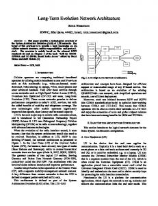
Figure 5: BLER curves obtained from SISO AWGN simulations for all 15 CQI values. From CQI 1 (leftmost) to CQI 15 (righmost)
In this section, we present some exemplary simulation results that were obtained using the standard compliant LTE link level simulator described in Section 3. These results are provided for comparison reasons to other simulators and also to show that the simulator is fully functioning. The common simulation settings for the results presented in the next two sections are summarized in Table 2. The SNR in the simulator is defined as the subcarrier SNR (that is the sum of the data subcarrier signal powers divided by sum of the noise powers received on all data subcarriers).
overall BLER
no retransmission
0
10
3 retransmissions 2 retransmissions 1 retransmission -1
10
.. .
.
SNR shifts due to HARQ (BLER=10%)
BLER
5. LTE PHYSICAL LAYER PERFORMANCE RESULTS
-2
10
5.1 BLER Results To obtain the Block Error Ratio (BLER) and throughput for the Modulation and Coding Scheme (MCS) corresponding to each CQI value, AWGN simulations were performed. The MCS determines both the modulation alphabet and the Effective Code Rate (ECR) of the channel encoder. Figure 5 shows the BLER results of CQIs 1-15 without using HARQ. Each curve is spaced approximately 2 dB from each other. When allowing retransmissions, BLER curves as shown in Figure 6 are obtained. In LTE, adaptive modulation and coding has to ensure a BLER value smaller than 10 %. The SINR-toCQI mapping required to achieve this goal can thus be obtained by plotting the 10 % BLER values of the curves in Figure 5 over SNR, like it is shown in Figure 7. Using the obtained line, an effective SINR can be mapped to a CQI value that is signalled to the eNodeB. Besides the CQI mapping on the physical layer, AWGN BLER curves are utilized in system level simulations to obtain the error probability of a received block as a function of the SINR and the MCS. When working with frequencyselective channels, an SINR averaging algorithm is required in order to compress the subcarrier SINR values into an effective SINR which is subsequently mapped to a CQI. Non-linear averaging methods such as the Exponential Effective SINR Mapping (EESM) [61–63] are usually employed to perform this compression.
-3
10
-8
-6
-4
-2
0
SNR [dB]
2
4
6
Figure 6: Resulting BLER at CQI=7 for different number of allowed retransmissions.
5.2 Throughput Results In this subsection, the throughput results are compared to the system capacity3 C of an AWGN channel calculated according to C = F B log2 (1 + SNR).
(1)
Here, SNR is the Signal to Noise Ratio, B the bandwidth occupied by the data subcarriers, and F a correction factor. The bandwidth B is calculated as B=
Nsc · Ns · Nrb , Tsub
(2)
where Nsc = 12 is the number of subcarriers in one RB, Ns is the number of OFDM symbols in one subframe (usually equal to fourteen when the normal Cyclic Prefix 3 We define as system capacity the Shannon capacity adjusted by the inherent system losses.
1475
0 10 SNR [dB]
20
30
15 14 13 12 11 10 9 8 7 6 5 4 3 2 1 0 −20
7 6
−10
0 10 SNR [dB]
20
throughput [Mbit/s]
−10
8
SNR−CQI mapping model
CQI
CQI
simulated SNR−CQI mapping 15 14 13 12 11 10 9 8 7 6 5 4 3 2 1 0 −20
30
Figure 7: CQI mapping.
BLER=10% points from the BLER curves (left) and SINR-to-CQI mapping function (right)
adaptive CQI
4 3 2
0 -25
-20
-15
-10
-5
0
5
10
15
20
25
SNR [dB]
7
Figure 9: Throughput performance with AMC and HARQ
6
throughput [Mbit/s]
5
1
8
over an AWGN channel.
system capacity
5 4 CQIs 10-15, 64-QAM CQIs 7-9, 16-QAM
3
CQIs 1-6, QPSK
2 1 0 -25
system capacity
-20
-15
-10
-5
0
5
10
15
20
25
SNR [dB]
Figure 8: Throughput performance over an AWGN channel for individual CQIs without HARQ.
5.3 MIMO Throughput Results
(CP) is set), Nrb is the number of RBs that fit into the selected system bandwidth (for example 6 RBs within a 1.4 MHz system bandwidth), and Tsub is the duration of one subframe equal to 1 ms. The transmission of an OFDM signal requires also the transmission of a CP to avoid inter-symbol interference and the reference symbols for channel estimation. Therefore, the well-known Shannon formula is adjusted in Equation (1) by the factor4 F . This factor F accounts thus for the inherent system losses and is calculated as F =
Nsc · Ns /2 − 4 Tframe − Tcp · , Tframe Nsc · Ns /2 | {z } | {z } CP loss reference symbol loss
achievable capacity is around 2 dB for most of the CQI values. The distance from the capacity curve is increasing with increasing CQI value which is explained by the non-Gaussian QAM constellations. The throughput with AMC is depicted in Figure 9 for one user that obtains all the available resources. This user reports the actual CQI obtained by mapping the measured SNR according to Figure 7. Note that the performance in Figures 8 and 9 looks very similar, although a maximum number of three retransmissions is allowed for the simulation in Figure 9. The reason for the similar performance is that in an AWGN channel the switching between the modulation and coding schemes can be done perfectly and hardly any retransmissions are required (although allowed if necessary).
(3)
where Tframe is the fixed frame duration equal to 10 ms and Tcp is the total CP time of all OFDM symbols within one frame. In Figure 8, the throughput curves are plotted for every CQI value. Here, HARQ is switched off and no retransmissions are performed. The SNR gap from the
In Figure 10, the data throughput of SISO, 2×1 transmit diversity (TxD), 4×2 transmit diversity, and 4×2 Open Loop Spatial Multiplexing (OLSM) is compared when transmitting over an uncorrelated ITU Pedestrian B channel. In this simulation we set the CQI to a fixed value of seven and the maximum number of HARQ retransmissions to three. The maximum throughput values achieved by the different MIMO schemes in Figure 10 depends (1) on the number of transmit antennas and (2) on the number of data streams (layers). If more transmit antennas are utilized for the transmission, more pilot symbols are inserted in the OFDM frame and thus lower maximum throughput can be achieved. In the case of OLSM, two spatially separated data streams are transmitted thus leading to twice the maximum throughput of the 4×2 TxD system. Note that the results in Figure 10 were obtained without channel adaptive precoding. An additional gain of the TxD schemes can therefore be expected when the PCI is utilized.
4 Note that the loss in the transmission efficiency due to the synchronization signal is negligible as it does not appear in every subframe. We therefore do not consider it here.
1476
2.5 OLSM 4x2
[10]
throughput [Mbps]
2.0
[11] 1.5 TxD 2x1
[12]
1.0
[13]
0.0
SISO
TxD 4x2
0.5
[14]
−5
0
5
20
[15]
Figure 10: Throughput performance of the 4×2 Open Loop
[16]
SNR [dB]
10
15
Spatial Multiplexing (OLSM), the 4×2 Transmit Diversity (TxD), the 2×1 Transmit Diversity, and the SISO system over an uncorrelated ITU Pedestrian B channel (CQI 7, 3 HARQ retransmissions).
[17] [18]
Acknowledgment The authors would like to thank the whole LTE research group for continuous support and lively discussions. This work has been funded by mobilkom austria AG, the Christian Doppler Laboratory for Wireless Technologies for Sustainable Mobility, as well as the Institute of Communications and Radio-frequency Engineering.
[19] [20]
[21]
References [1] [Online]. Available: http://www.nt.tuwien.ac.at/ltesimulator/ [2] 3GPP, “Technical specification group radio access network; (E-UTRA) and (E-UTRAN); overall description; stage 2,” Sep. 2008. [Online]. Available: http://www.3gpp.org/ftp/ Specs/html-info/36300.htm [3] E. Dahlman, S. Parkvall, J. Sk¨ old, and P. Beming, 3G Evolution – HSPA and LTE for Mobile Broadband, 1st ed. Academic Press, 2007. [4] H. Holma, A. Toskala, K. Ranta-aho, and J. Pirskanen, “High-speed packet access evolution in 3GPP release 7,” IEEE Communications Magazine, vol. 45, no. 12, pp. 29–35, Dec. 2007. [5] E. Dahlman, H. Ekstrom, A. Furuskar, Y. Jading, J. Karlsson, M. Lundevall, and S. Parkvall, “The 3G longterm evolution - radio interface concepts and performance evaluation,” in Proc. 63rd IEEE Vehicular Technology Conference 2006 (VTC2006-Spring), vol. 1, May 2006, pp. 137–141. [6] H. Ekstrom, A. Furuskar, J. Karlsson, M. Meyer, S. Parkvall, J. Torsner, and M. Wahlqvist, “Technical solutions for the 3G long-term evolution,” IEEE Communications Magazine, vol. 44, no. 3, pp. 38–45, Mar. 2006. [7] S. Parkvall, E. Dahlman, A. Furuskar, Y. Jading, M. Olsson, S. Wanstedt, and K. Zangi, “LTE-advanced - evolving LTE towards IMT-advanced,” in Proc. 68th IEEE Vehicular Technology Conference 2008 (VTC2008-Fall), Sep. 2008. [8] M. Tanno, Y. Kishiyama, N. Miki, K. Higuchi, and M. Sawahashi, “Evolved UTRA - physical layer overview,” in Proc. IEEE 8th Workshop on Signal Processing Advances in Wireless Communications 2007 (SPAWC 2007), Jun. 2007. [9] J. J. S´ anchez, D. Morales-Jim´ enez, G. G´ omez, and J. T. Enbrambasaguas, “Physical layer performance of long term
[22]
[23]
[24]
[25]
[26]
[27]
[28]
1477
evolution cellular technology,” in Proc. 16th IST Mobile and Wireless Communications Summit 2007, Jul. 2007. T. Tang and R. Heath, “Opportunistic feedback for downlink multiuser diversity,” IEEE Communications Letters, vol. 9, no. 10, pp. 948–950, Oct. 2005. A. Gyasi-Agyei, “Multiuser diversity based opportunistic scheduling for wireless data networks,” IEEE Communications Letters, vol. 9, no. 7, pp. 670–672, Jul. 2005. J. Andrews, “Interference cancellation for cellular systems: a contemporary overview,” IEEE Transactions on Wireless Communications, vol. 12, no. 2, pp. 19–29, Apr. 2005. A. Simonsson, “Frequency reuse and intercell interference co-ordination in E-UTRA,” in Proc. 65th IEEE Vehicular Technology Conference 2007 (VTC2007-Spring), Apr. 2007, pp. 3091–3095. H. Zhang, L. Venturino, N. Prasad, and S. Rangarajan, “Distributed inter-cell interference mitigation in OFDMA wireless data networks,” in Proc. 4th IEEE Broadband Wireless Access Workshop, New Orleans, LA, USA, Dec. 2008. S. Ascent, “3GPP LTE toolbox and blockset.” [Online]. Available: http://www.steepestascent.com/content/default. asp?page=s2 10 mimoOn, “mi!Mobile.” [Online]. Available: http://www. mimoon.de/pages/Products/miMobile/ Aricent, “LTE layer 1 - LTE baseband/PHY library.” [Online]. Available: http://www.aricent.com/Expertise/ LTE.aspx J. J. S´ anchez, G. G´ omez, D. Morales-Jim´ enez, and J. T. Entrambasaguas, “Performance evaluation of OFDMA wireless systems using WM-SIM platform,” in Proc. 4th ACM International Workshop on Mobility Management and Wireless Access (MobiWac 2006), Terromolinos, Spain, 2006, pp. 131–134. Mathworks. [Online]. Available: http://www.mathworks. com/products/matlab/ C. Mehlf¨ uhrer, S. Caban, and M. Rupp, “Experimental evaluation of adaptive modulation and coding in MIMO WiMAX with limited feedback,” EURASIP Journal on Advances in Signal Processing, Special Issue on MIMO Systems with Limited Feedback, vol. 2008, Article ID 837102, 2008. Q. Wang, C. Mehlf¨ uhrer, and M. Rupp, “SNR optimized residual frequency offset compensation for WiMAX with throughput evaluation,” in Proc. 17th European Signal Processing Conference (EUSIPCO 2009), Glasgow, Scotland, Aug. 2009. Q. Wang, S. Caban, C. Mehlf¨ uhrer, and M. Rupp, “Measurement based throughput evaluation of residual frequency offset compensation in WiMAX,” in Proc. 51st International Symposium ELMAR-2009, Zadar, Croatia, Sep. 2009. N. Kolehmainen, J. Puttonen, P. Kela, T. Ristaniemi, T. Henttonen, and M. Moisio, “Channel quality indication reporting schemes for UTRAN long term evolution downlink,” in Proc. 67th IEEE Vehicular Technology Conference 2008 (VTC2008-Spring), May 2008, pp. 2522– 2526. L. Boher, R. Legouable, and R. Rabineau, “Performance analysis of iterative receiver in 3GPP/LTE DL MIMO OFDMA system,” in Proc. IEEE 10th International Symposium on Spread Spectrum Techniques and Applications 2008 (ISSSTA 2008), Aug. 2008, pp. 103–108. J. C. Ikuno, M. Wrulich, and M. Rupp, “Performance and modeling of LTE H-ARQ,” in Proc. International ITG Workshop on Smart Antennas (WSA 2009), Berlin, Germany, Feb. 2009. C. Mehlf¨ uhrer, S. Caban, M. Wrulich, and M. Rupp, “Joint throughput optimized CQI and precoding weight calculation for MIMO HSDPA,” in Conference Record of the 42nd Asilomar Conference on Signals, Systems and Computers, Pacific Grove, CA, USA, Oct. 2008. M. Wrulich, S. Eder, I. Viering, and M. Rupp, “Efficient linkto-system level model for MIMO HSDPA,” in Proc. of the 4th IEEE Broadband Wireless Access Workshop, New Orleans, LA, USA, Dec. 2008. C. Ribeiro, K. Hugl, M. Lampinen, and M. Kuusela, “Performance of linear multi-user MIMO precoding in LTE system,” in Proc. 3rd International Symposium on Wireless
[29]
[30]
[31]
[32]
[33]
[34]
[35]
[36]
[37]
[38] [39]
[40]
[41]
[42]
[43]
[44] [45] [46] [47] [48]
Pervasive Computing 2008 (ISWPC 2008), May 2008, pp. 410–414. M. Wrulich, C. Mehlf¨ uhrer, and M. Rupp, “Interference aware MMSE equalization for MIMO TxAA,” in Proc. 3rd International Symposium on Communications, Control and Signal Processing (ISCCSP 2008), St. Julians, Malta, Mar. 2008, pp. 1585–1589. C. Mehlf¨ uhrer, M. Wrulich, and M. Rupp, “Intra-cell interference aware equalization for TxAA HSDPA,” in Proc. 3rd IEEE International Symposium on Wireless Pervasive Computing (ISWPC 2008), Santorini, Greece, May 2008, pp. 406–409. A. Ibing and V. Jungnickel, “Joint transmission and detection in hexagonal grid for 3GPP LTE,” in Proc. International Conference on Information Networking 2008 (ICOIN 2008), Jan. 2008. M. Wrulich, W. Weiler, and M. Rupp, “HSDPA performance in a mixed traffic network,” in Proc. 67th IEEE Vehicular Technology Conference Spring (VTC2008-Spring), Singapore, May 2008, pp. 2056–2060. M. Wrulich and M. Rupp, “Efficient link measurement model for system level simulations of Alamouti encoded MIMO HSDPA transmissions,” in Proc. ITG International Workshop on Smart Antennas (WSA 2008), Darmstadt, Germany, Feb. 2008. S. Caban, C. Mehlf¨ uhrer, G. Lechner, and M. Rupp, ““Testbedding” MIMO HSDPA and WiMAX,” in Proc. 70th IEEE Vehicular Technology Conference (VTC2009-Fall), Anchorage, AK, USA, Sep. 2009. M. Rupp, S. Caban, and C. Mehlf¨ uhrer, “Challenges in building MIMO testbeds,” in Proc. 15th European Signal Processing Conference (EUSIPCO 2007), Pozna´ n, Poland, Sep. 2007. M. Rupp, C. Mehlf¨ uhrer, S. Caban, R. Langwieser, L. W. Mayer, and A. L. Scholtz, “Testbeds and rapid prototyping in wireless system design,” EURASIP Newsletter, vol. 17, no. 3, pp. 32–50, Sep. 2006. S. Caban, C. Mehlf¨ uhrer, R. Langwieser, A. L. Scholtz, and M. Rupp, “Vienna MIMO testbed,” EURASIP Journal on Applied Signal Processing, Special Issue on Implementation Aspects and Testbeds for MIMO Systems, vol. 2006, Article ID 54868, 2006. [Online]. Available: http://www.nt.tuwien.ac.at/wimaxsimulator/ C. Mehlf¨ uhrer, S. Caban, and M. Rupp, “MIMO HSDPA throughput measurement results in an urban scenario,” in Proc. 70th IEEE Vehicular Technology Conference (VTC2009-Fall), Anchorage, AK, USA, Sep. 2009. J. A. Garc´ıa-Naya, C. Mehlf¨ uhrer, S. Caban, M. Rupp, and C. Luis, “Throughput-based antenna selection measurements,” in Proc. 70th IEEE Vehicular Technology Conference (VTC2009-Fall), Anchorage, AK, USA, Sep. 2009. R. Stuhlberger, R. Krueger, B. Adler, J. Kissing, L. Maurer, G. Hueber, and A. Springer, “LTE-downlink performance in the presence of RF-impairments,” in Proc. European Conference on Wireless Technologies 2007, Oct. 2007, pp. 189–192. 3GPP, “Technical specification group radio access network; evolved universal terrestrial radio access (E-UTRA); multiplexing and channel coding (release 8),” Mar. 2008. [Online]. Available: http://www.3gpp.org/ftp/Specs/ archive/36 series/36.212/ A. Nimbalker, Y. Blankenship, B. Classon, and T. K. Blankenship, “ARP and QPP interleavers for LTE turbo coding,” in Proc. IEEE Wireless Communications and Networking Conference 2008 (WCNC 2008), Las Vegas, NV, USA, Mar. 2008. “Iterative Solutions Coded Modulation Library (ISCML).” [Online]. Available: http://www.iterativesolutions.com/ “GNU lesser general public license, version 2.1.” [Online]. Available: http://www.gnu.org/licenses/lgpl-2.1.html “pycrc CRC calculator and C source code generator.” [Online]. Available: http://www.tty1.net/pycrc/ “MIT license.” [Online]. Available: http://www.opensource. org/licenses/mit-license.php “MEX-files Guide.” [Online]. Available: http://www. mathworks.com/support/tech-notes/1600/1605.html
[49] “Recommendation ITU-R M.1225: Guidelines for evaluation of radio transmission technologies for IMT-2000,” Tech. Rep., 1997. [50] 3GPP, “Technical specification group radio access network; deployment aspects (release 7),” 3GPP, Tech. Rep. 25.943 V7.0.0, Jun. 2007. [51] Y. R. Zheng and C. Xiao, “Simulation models with correct statistical properties for rayleigh fading channels,” IEEE Transactions on Communications, vol. 51, no. 6, pp. 920– 928, Jun. 2003. [52] T. Sorensen, P. Mogensen, and F. Frederiksen, “Extension of the ITU channel models for wideband (OFDM) systems,” in Proc. IEEE 62nd Vehicular Technology Conference 2005 (VTC2005-Fall), Sep. 2005. [53] C. Mehlf¨ uhrer, F. Kaltenberger, M. Rupp, and G. Humer, “A scalable rapid prototyping system for real-time MIMO OFDM transmissions,” in Proc. 2nd IEE/EURASIP Conference on DSP enabled Radio, Southampton, UK, Sep. 2005. [54] C. Mehlf¨ uhrer, F. Kaltenberger, M. Rupp, and G. Humer, “Low-complexity MIMO channel simulation by reducing the number of paths,” in Proc. ITG/IEEE Workshop on Smart Antennas (WSA 2007), Vienna, Austria, Feb. 2007. [55] C. Mehlf¨ uhrer and M. Rupp, “Approximation and resampling of tapped delay line channel models with guaranteed channel properties,” in Proc. IEEE International Conference on Acoustics, Speech and Signal Processing (ICASSP 2008), Las Vegas, NV, USA, Mar. 2008, pp. 2869–2872. [56] J. Salo, G. Del Galdo, J. Salmi, P. Ky¨ osti, M. Milojevic, D. Laselva, and C. Schneider. (2005, Jan.) MATLAB implementation of the 3GPP Spatial Channel Model (3GPP TR 25.996). [Online]. Available: http://www.tkk.fi/Units/ Radio/scm/ [57] 3GPP, “Technical specification group radio access network; spatial channel model for Multiple Input Multiple Output (MIMO) simulations (release 8),” 3GPP, Tech. Rep. 25.996 V8.0.0, Dec. 2008. [58] D. Baum, J. Hansen, and J. Salo, “An interim channel model for beyond-3G systems: extending the 3GPP spatial channel model (SCM),” in Proc. IEEE 61st Vehicular Technology Conference 2005 (VTC2005-Spring), Stockholm, Sweden, May 2005. [59] L. Hentil¨ a, P. Ky¨ osti, M. K¨ aske, M. Narandzic, and M. Alatossava. (2007, Dec.) MATLAB implementation of the WINNER phase ii channel model ver1.1. [Online]. Available: http://www.ist-winner.org/phase 2 model.html [60] C. Studer, M. Wenk, A. P. Burg, and H. B¨ olcskei, “Softoutput sphere decoding: Performance and implementation aspects,” in Conference Record of the 40th Asilomar Conference on Signals, Systems and Computers, Pacific Grove, CA, USA, Nov. 2006. [61] E. Tuomaala and H. Wang, “Effective SINR approach of link to system mapping in OFDM/multi-carrier mobile network,” in Proc. 2nd International Conference on Mobile Technology, Applications and Systems 2005, Nov. 2005. [62] X. He, K. Niu, Z. He, and J. Lin, “Link layer abstraction in MIMO-OFDM system,” in Proc. International Workshop on Cross Layer Design 2007 (IWCLD 2007), Sep. 2007, pp. 41–44. [63] R. Sandanalakshmi, T. Palanivelu, and K. Manivannan, “Effective SNR mapping for link error prediction in OFDM based systems,” in Proc. IET-UK International Conference on Information and Communication Technology in Electrical Sciences (ICTES 2007), Dec. 2007, pp. 684–687.
1478