Simulation Framework for the Estimation of Future Interference Situations between Automotive Radars Tom Schipper, Silvia Prophet, Lukasz Zwirello, Marlene Harter, Lars Reichardt and Thomas Zwick Karlsruhe Institute of Technology (KIT) Institut f¨ur Hochfrequenztechnik und Elektronik (IHE) 76131 Karlsruhe
[email protected] Abstract—Interference between automotive radar systems is becoming an important topic of research today, since the density of automotive radars is rising continuously. However, the total amount of cars equipped with radar is still below one percent. This paper introduces a method to predict future interference conditions between automotive radars for higher penetration rates and presents selected results.
the SET. It connects the channel information with information about all involved radar systems and provides functions for system simulation and analysis. More information about the simulation framework and it’s application can be found in [2]. The suitability of the simulator was documented additionaly during the project MOSARIM [3], [4].
I. I NTRODUCTION Nowadays vehicles are equipped with radars to realize Advanced Driver Assistance Systems (ADAS). A common setup is a forward looking radar to enable Automatic Cruise Control (ACC) and two backward looking radars to provide Blind Spot Detection (BSD) and a Lane Change Assist (LCA). Overall, the number of radars on our streets is constantly increasing. Unlike the gyroscope and accelerometer of the Electronic Stability Program (ESP), radars can be influenced by emissions of other radars in the same band. The issue of multiple interference between vehicles was already adressed by Hischke in 1995 [1]. The paper presented here introduces a profound simulation framework, which includes a 3D wave propagation model and a determinstic traffic flow simulator to answer the question, which interference power levels could be expected in the future. In chapter II, a short overview of the simulation framework is given.
Fig. 1.
III. E XTENSION OF THE SIMULATION FRAMEWORK REGARDING LONG - TERM OBSERVATIONS
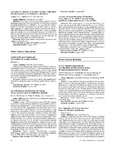
II. T HE BASIC SIMULATION FRAMEWORK The simulation framework is sketched in Fig. 1 and is now briefly described: A Scenario Editing Tool (SET) helps to create arbitrary traffic scenarios. The SET allows the import and creation of polygon based structures, the definition of trajectories and further the full control of the electrical parameters, surface roughness and scattering behaviour of objects. The SET is used to generate exactly specified scenarios as an input for the wave propagation simulation, performed by a 3D RayTracing Tool (RTT) based on the Geometric Optics (GO). Multiple reflections and diffractions are supported, as well as modified Fresnel reflection coefficients to consider rough surfaces. Vegetation is modeled by arbitrary scattering sources, which can also be used to model a certain radar cross-section behaviour. A simulation flow control software, written in MATLAB, coordinates the interaction between the RTT and
978-1-4673-5317-5/13/$31.00 ©2013 IEEE
The simplified simulation framework
Modeling longer periods of driving with the SET is not practicable. The SET is predestined for short term scenarios of several seconds or minutes, especially for traffic situations like near misses or accidents. To get an idea of the interference situation in a real world scenario over a longer period of time, the scenarios must be created automatically and with the highest possible degree of realism. To meet this demand, a traffic flow simulator is coupled with the simulation framework as sketched in Fig. 1. This traffic flow simulator [5] considers realistic person- and environment-dependent driving behaviour. The traffic flow can be protocolled over several hours, fed into the existing simulation framework and analyzed. IV. E STIMATION OF FUTURE INTERFERENCE CONDITIONS Now an example is given, how to predict future interference conditions. The vehicle composition is configured on the basis
2103
AP-S 2013
uncorrelated FMCW interferers is investigated in [7], [8] and can roughly be estimated for radars with I/Q receivers by GS/I = BW · T
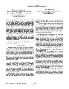
−85 −90 −95 −100 −105 Max. received interference power 9/10−Quantiles 1/10−Quantiles
−110 −115 10
20
Fig. 4. Fig. 2.
(1)
where BW is the sweep bandwidth of the FMCW radar in Hz and T is the observation time in seconds. If the FMCW radar has no IQ-receiver the GS/I is up to 6 dB less. Dependent on the involved waveforms and hardware details, GS/I differs. Incoherent received interference power [dBW]
of traffic censuses [6], a two lane straight street is chosen and a traffic flow rate of 1000 vehicles per hour and lane is set. Fig. 2 visualizes this setup for one snapshot, in which the victim car (the car, for which the received interference power is assessed) is chosen randomly out of the defined area. Fig. 3 shows the radar configuration of the vehicles. The setup is assumed to be a worst case. All radars have an EIRP (Equivalent Isotropically Radiated Power) of 20 dBm and a carrier frequency of 24.125 GHz, what is equal to the simulation frequency, that is used for the wave propagation simulation.
30
40
50
60
Radar penetration rate [%]
70
80
90
100
Compilation of quantiles for different RPR
V. CONCLUSION In this paper an extended simulation framework for radar applications was demonstrated by estimating future interference power levels for automotive radars under certain worst case assumptions. The examplary simulation results underline the importance of reliable interference countermeasures in order to retain the performance of radars.
Cars are bright, trucks are dark. Also visible: lane changes
ACKNOWLEDGMENT The research leading to these results has received funding from the European Community’s Seventh Framework Programme (FP7/2007-2011) under grant agreement n◦ 248 231 - MOSARIM Project. Fig. 3.
The assumed radar configuration of cars and trucks
Five hours of driving are simulated with 10 different Radar Penetration Rates (RPR: the ratio between cars equipped with radars and all cars). The step size is 4 seconds, resulting in 4500 snapshots for every RPR. For every snapshot the total incoherent received interference power at the victim radar’s antenna port is calculated. This data leads to 10 Cumulative Distribution Functions (CDF), one for each RPR. For an ACC victim radar, the 1/10 and the 9/10 quantiles of these CDFs are drawn in Fig. 4, as well as the total maximum received interference power levels. An intuitive, but important outcome of Fig. 4 is, that the total maximum received interference power levels stay more or less the same, while the 1/10 and 9/10 quantiles are rising. This means for an RPR of 100 %, that in 90 % of the time the interference power levels differ equal or less than 10 dB from the overall maximum received interference power level. There is no gain versus interference mentioned in this paper up to now. The total gain of FMCW radars versus nearly
R EFERENCES [1] M. Hischke, “Collision warning radar interference,” in Intelligent Vehicles ’95 Symposium., Proceedings of the, Sep. 1995, pp. 13 –18. [2] T. Schipper, M. Harter, L. Zwirello, T. Mahler, and T. Zwick, “Systematic Approach to Investigate and Counteract Interference-Effects in Automotive Radars,” in European Radar Conference (EuRAD), Amsterdam, The Netherlands, Nov. 2012. [3] MOSARIM consortium, “Simulation setup assessment: Interferer - free space propagation - victim radar,” in Workpackage: General Interference Risk Assessment, www.mosarim.eu, Dec. 2011. [4] MOSARIM consortium, “Validation check of simulation models with selected real world laboratory tests,” in Workpackage: General Interference Risk Assessment, www.mosarim.eu, Dec. 2012. [5] PTV AG, “VISSIM, macroscopic simulation tool for traffic flow modeling,” in PTV Planung Transport Verkehr AG, Karlsruhe, Germany, www.ptv-vision.com, 1992. [6] Bundesanstalt f¨ur Verkehrswesen (BASt), Automatische Z¨ahlstellen 2010, in http://www.bast.de, Dec. 2012. [7] D. Oprisan and H. Rohling, “Analysis of mutual interference between automotive radar systems,” in International Radar Symposium (IRS), 2005, Berlin, Germany, Sep. 2005, pp. 1–4. [8] M. Goppelt, H.-L. Bl¨ocher, and W. Menzel, “Analytical investigation of mutual interference between automotive FMCW radar sensors,” in Microwave Conference (GeMIC), 2011 Germany, Mar. 2011, pp. 1–4.
2104