Simulation Interoperability Workshop, Orlando, Fall 2000 Paper 00F-SIW-035
Simulation Infrastructure for the DII COE Architecture: The Army Vision Michael R. Hieb, Ph.D. IITRI/AB Technologies Group 1901 N. Beauregard St. Alexandria, VA 22311-1705 (703) 933-3376
[email protected]
Ron Sprinkle The AEgis Technologies Group 12565 Research Parkway Orlando, FL 32765 (407) 380-5001
[email protected]
Keywords: ABCS, Communications, C4ISR, Data, DII COE, Exercise Control, HLA, Interoperability, JTA, Logistics, Terrain ABSTRACT: Key to the future interoperability of Simulations with Command, Control, Communications, Computers, Intelligence, Surveillance and Reconnaissance (C4ISR) systems is the Defense Information Infrastructure Common Operating Environment (DII COE) architecture. The DII COE is composed of configurable, layered, reusable software components that work together with specific C4ISR mission software to perform a task. All future DoD C4I systems will design to the DII COE. However, because Modeling and Simulation (M&S) has not been involved with the development of DII COE components to date, simulation capabilities fall short. This paper describes a long-term vision of how to "architect" M&S functionality into the DII COE over the next 10 to 20 years by describing an objective end-state. To define this vision, four design options for integrating simulation functionality with the DII COE are identified. The four options are intended to accommodate the major design alternatives. These range from keeping simulations totally separate from the DII COE (as is the case now) to building in embedded simulation functionality into DII COE software components. Analyzing these options assists in answering many questions that arise when considering simulation in the DII COE, such as how the High Level Architecture (HLA) relates to the DII COE and how simulations can support C4ISR System embedded training. The construction and analysis of the four design options facilitates the selection of a recommended course of action for the future. Without a plan for the future, it will be difficult to meet simulation requirements for C4ISR Systems, as 1) the DII COE will lack necessary functionality and 2) simulations will not be able to co-exist on DII COE platforms. Determining the objective is the first step to any plan. This paper presents such a long-term vision.
1. Introduction 1.1 Opportunity With the establishment of the Defense Information Infrastructure Common Operating Environment (DII COE) architecture, the Command, Control, Communications, Computers, Intelligence, Surveillance and Reconnaissance (C4ISR) domain has come a long way towards true interoperability both in the Army and among the Services. The DII COE provides both a detailed architecture and a process for building common components in a coordinated fashion. With the creation of a Modeling and Simulation (M&S) Technical Working Group (TWG) within the DII COE management process, it is time to specify a vision of how the Army will plan its simulation coordination with the
DII COE within the next 10 to 20 years. This paper presents an analysis of the various options available to the simulation domain and makes recommendations for future development. C4ISR to M&S interoperability is currently facilitated by software interfaces established between specific systems. The development of C4ISR to M&S interfaces has not been considered one of the primary design requirements for either type of system. Most of the existing C4ISR interfaces to M&S have been developed as a separate component, added on after initial M&S development. Existing interfaces typically handle a small subset of the messages or data necessary for interoperability, requiring significant human intervention to achieve realism for the training audience in an exercise. M&S systems, for instance, rarely handle free text messages or consider
Simulation Interoperability Workshop, Orlando, Fall 2000 Paper 00F-SIW-035, Page 2
how a message is carried (communication effects). C4ISR systems have been subject to different design constraints than M&S systems, resulting in different standards, message formats and protocols. Since any interface between the systems must align these differences, the interface can become quite complex. 1.2 Thesis Legacy systems and the lack of standard architectures have worked together in the past to frame the issue of C4ISR to M&S interoperability as one of interfaces. We believe that these interfaces, while necessary, are only one component of interoperability. Recent interface projects such as the Modular Reconfigurable C4ISR Interface (MRCI) [11] provide lessons learned that have shaped our approach. Complete interoperability can only be addressed by consideration of several different aspects such as standards, architectures, data models and processes. 1.3 Scope Concurrent with the M&S community’s standardization of the High Level Architecture (HLA), the C4ISR community has moved to standardize on the Joint Technical Architecture (JTA) [8] and the Defense Information Infrastructure Common Operating Environment (DII COE). Currently, the Army is investing heavily in developing its tactical suite of C4ISR systems, the Army Battle Command System (ABCS). The DII COE is central to ABCS development.
SIMNET
CBS AWSIM ...
In this paper we will use the JTA terminology to refer to the different “domains”. The JTA specifies within its main body, standards that apply to all systems. However, the JTA recognizes that these standards may be too general for certain applications and thus provides domains for four classes of applications. The JTA addresses domains through appendices to the main document that contain exceptions (replacing a core standard with a domain standard) or extensions (that add a domain standard to the main body set of standards). The domains are:
C4ISR; Weapon Systems; Modeling and Simulation; and Combat Support
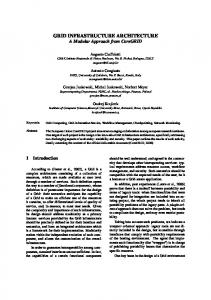
We take this vision out beyond the current specific development cycles to address functionality and processes to avoid specific software and hardware limitations imposed by the present architectures. To formulate a vision, one must recognize that the present architecture and systems will evolve. Figure 1 shows a view of the past evolution and a possible future, starting 10 years ago and looking ahead 20 years. The Simulation Network (SIMNET) protocol was initially used to link tank simulators together, developed into a more generalized protocol, the Distributed Interactive Simulation (DIS) that allowed a wide variety of entity-level simulations to operate together. In the same timeframe, the Aggregate Level Simulation Protocol was developed to link together large training
Common Data Access
DIS HLA
Event Control
DII COE
ALSP
Simulation Functions
WWMCCS
timeline
GCCS COE
DII COE
now
FUTURE COMMON ARCHITECTURE
Common Terrain
10 yrs
20 yrs
Figure 1: Evolution of C4ISR and Distributed Simulation Architectures
Simulation Interoperability Workshop, Orlando, Fall 2000 Paper 00F-SIW-035, Page 3
models such as the Corps Battle Simulation (CBS) and the Air Warfare Simulation (AWSIM). Both ALSP and DIS influenced the development of the current simulation architecture, the HLA. Similarly, for C4I, the World-Wide Military Command and Control System (WWMCCS) developed into the Global Command and Control System (GCCS) Common Operating Environment (COE), and was the basis for the DII COE.
Interoperability of Legacy and Future Systems
M&S
C4ISR Shared Solutions Reusable Component Interfaces
In the future, as shown in Figure 1, we see the Common Processes architectures becoming more similar, rather than Common Data/Object For diverging. As will be discussed in Section 4, Standards Models Alignment C4ISR functionality will overlap M&S functionality in the future to some extent. To specify a vision for the future, we look ahead 10 Architecture to 20 years. We are not specifically addressing Alignment legacy system interoperability in this paper as many excellent solutions currently exist, but are Figure 2: “House” of Interoperability rather focused on future development. In the future, new C4ISR systems and simulations will be built. Within the C4ISR domain, these systems must Architecture. Section 4 presents four options for how be built to the DII COE architecture, using standard data simulations can interoperate with the DII COE models such as the Joint Common Data Base (JCDB) [6]. architecture and uses these design options to describe a We specify this vision to influence the development of vision of DII COE interoperability for simulations in the these systems in the future – both simulations and C4ISR next 10 to 20 years. Section 5 concludes with a recommendation and considers the implications of the systems. vision presented. The scope of this paper is bounded by those systems supported by the DII COE and the simulations that must 2. Framework for C4I/M&S Interoperability either connect to or be embedded within these systems. In addition, we only consider C4ISR systems and Simu- This section presents two interoperability frameworks lations within the definition of the JTA and not the other developed over several years. We discuss the “House domains (Weapons and Combat Support). We divide Diagram” and present a C4ISR/M&S Interoperability These discussions provide the simulations into two broad categories – 1) those that Reference Model. must interoperate with C4ISR systems; and 2) those that background for subsequent sections. do not need to interoperate. Thus, if a future simulation “touches” the C4ISR domain (e.g. by stimulating a 2.1 The House Diagram tactical system for training or by consuming data for strategic analysis) it falls within this vision. If the The “House Diagram” in Figure 2 is a comprehensive simulation does not interact with either C4ISR systems or view of interoperability between C4ISR and M&S the data used and generated by these C4ISR systems (e.g. systems. To reach the interoperability objective, five a system used for simulating the physical phenomena of enablers are identified below and subsequently described in detail: airflow over a wing) it is not addressed here. While this paper is based primarily on Army C4ISR and Simulation systems, the vision is a Joint vision. Nothing in our approach is specific to one service. Both the Air Force and Navy are working on DII COE projects that are consistent with the vision presented here. The remainder of this paper is organized as follows. Section 2 presents a framework for C4ISR/M&S Interoperability. Section 3 describes DII COE
Architectures Alignment Common Data/Object Models Common Standards Processes to manage and align all efforts and respective results – and as a result of the above, Reusable Component Interfaces and shared solutions
Simulation Interoperability Workshop, Orlando, Fall 2000 Paper 00F-SIW-035, Page 4
Exercise Control Interactions Initialization/Execution Data Collection
C 4 I S y s t e m
Exercise Control Module
Non-Persistent Data Orders Reports Imagery Tracks
Behavior Models Module Physical Models Module Communication Model
Communications Effects
Persistent Data Unit Data (TOE, Symbology, etc) Mission & Plan Information Comms Plan (Radio/Network Setup, etc) Weather Data Terrain Specification
Environmental Models Module Run-time Framework
Scenario DB
M & S S y s t e m
Figure 3: C4ISR/M&S Interoperability Technical Reference Model Architecture Alignment recognizes that there are many ways to partition the “solution space”. The C4ISR community has developed the DII COE Architectures. The simulation community has the HLA. These architectures directly impact the technical basis upon which C4ISR and simulation systems are built. Alignment of architectures contrasts and resolves the differences in how architectures compartmentalize the “solution space” of the system(s) or system of systems. The alignment of Common Data Models (legacy C4ISR systems) with Object Models (new simulation systems) is often ignored [6]. However, having simulations use the same or similar model representation as the C4ISR system minimizes translation. Without both model and architecture alignment, the efforts represented by the rest of the blocks comprising the house diagram are limited to isolated interface successes such as seen today between stovepiped systems. Common Standards must be worked into system designs. Making sense of where and how to apply standards relies primarily on work being done on the architecture and data/object model alignment. Since little architecture and model alignment work has been done, it has been terribly difficult to set and use meaningful standards to assist interoperability challenges. Notice that we have set the Reusable Component Interfaces on top of and therefore dependent upon, the blocks below it. Compared to architectures, models and
standards, the interfaces area has been a hotbed of activity. One answer to this apparent paradox is that interfaces can provide short-term solutions that are easier to envision and allow quicker successes in a world of disparate systems. Translators in these interfaces help to convert data between systems, but never really remove basic underlying incompatibilities of model representation or architecture misalignment. Finally, the roof of the house diagram, Shared Solutions between C4ISR and Simulations is supported by the work of all the blocks below it including the Processes for Alignment, which provides policy and procedures for evolving the other house blocks. 2.2 The C4ISR/M&S Interoperability Technical Reference Model The C4ISR/M&S Interoperability Technical Reference Model shown in Figure 3 was developed to identify all possible types of information that could be exchanged between C4ISR and M&S systems. A notional Simulation is shown in Figure 3 with various software modules. Similarly, the C4ISR system consists of DII COE software modules, as will be described in Section 3. Figure 3 identifies three broad classes of information containing required elements that, if satisfied, would result in full data interoperability:
Persistent Data; Non-Persistent Data; and Exercise Control.
Simulation Interoperability Workshop, Orlando, Fall 2000 Paper 00F-SIW-035, Page 5
Persistent Data refers to the class of information that is stored during the operation of the simulation. Information belonging to this class is typically initialized prior to execution and changes less frequently than NonPersistent Data. Non-Persistent Data refers to the class of information that is transient, corresponding to interactions – during execution – between entities or objects in the simulation or C4ISR database. A third class of information necessary for a complete interface is Exercise Control. Simulations typically have a set of protocols that allow an operator to control their execution and synchronize their operation with other simulations. Current C4ISR systems do not have protocols that correspond to these, however future C4ISR systems must have such protocols to enable them to be fully interoperable with simulations. One example is the requirement for After Action Review. While simulations can typically replay a scenario that had previously occurred, it is desirable to synchronize C4ISR systems to scenario events for analysis. Unless these requirements are specified to C4ISR developers, future C4ISR systems will not have the capability to perform such operations. The Technical Reference Model is more fully described in [2, 7, 12].
3. DII COE Overview The DII COE was born in 1995 from the GCCS COE, which was adopted at the Department of Defense (DoD) level as a replacement for the WWMCCS. Because it is not only an architecture for configurable mission applications, but is also a philosophy, a process and a practice, the DII COE has been mandated as the basis for the creation of future C4ISR Systems. The JTA [9] gives the overall framework for developing systems within the DoD and specifies the use of the DII COE. 3.1 DII COE Fundamentals The users and developers of C4ISR systems recognized the need for standardization to reduce system-to-system interoperability issues and rampant redundancy. The Services have adopted the DII COE concept and mandated its baseline and integration & runtime specifications [8]. It is sometimes convenient to think of the layered software of the DII COE as an Operating System (OS). Since the DII COE may either be resident on Windows™ or UNIX platforms, it is obviously not an OS. It is a collection of software that collates common support
applications and augments infrastructure/kernel functions. This results in a DoD specific DII COE/Windows™ or DII COE/UNIX operating system. As such, the DII COE is not a system, but a foundation for building systems. As a system foundation the DII COE is mission application independent, as well as:
An architecture; An approach; A collection of reusable software; A software infrastructure; and A set of guidelines and standards.
The DII COE architecture and software infrastructure are addressed in Section 3.2 and the DII COE process is addressed in Section 3.3. Development of a DII COE compliant software component ultimately results in that software going through a segmentation process. This step is crucial for the independent and distributed development of applications. Thus, when a software component is made to work within the DII COE “environment” it is said to be segmented, and then can be submitted to DISA for compliance testing. The segmentation process requires that public Application Programmer’s Interfaces (APIs) be identified in the file structure or “Segment Directory”. This means that there is a process-enabled method for application developers to reuse previously accepted, compliant software with well-established public interfaces. 3.2 DII COE Architecture Figure 4 depicts the DII COE as a layered software architecture comprised of Mission Applications, Common Support Applications, Infrastructure Services, Kernel Services and Database Applications and services. The cubes shown are software modules. With the exception of Databases, the software layers are organized from the most common and generic at the Kernel level to unique and specific at the Mission Application level. Since their use is required by software existing in all the layers Databases can exist anywhere along the range from common to specific. The Databases layer contains intelligence, tactical C2 specific, combat support and tactical specific databases. The Kernel software runs on all DII COE compliant platforms and contains such things as Security System Management, Windowing Software (X-Windows, Windows™), Executive Management, network
Simulation Interoperability Workshop, Orlando, Fall 2000 Paper 00F-SIW-035, Page 6
configuration, disk management, install/de-install, kernel patches, printing, runtime services and the Operating Systems (Windows™, UNIX). All infrastructure, common applications and mission applications either directly or indirectly depend upon critical services contained in the Kernel. The Infrastructure layer software emphasizes the movement of data through the network of DII COE systems and contains communications, distributed computing, presentation and web, network management and data and object management services. The Infrastructure layer allows common and mission applications to take advantage of the distributed nature of DoD computing. The Common Support Applications layer begins to address interoperability through an emphasis on a common view of the data and contains message processing, alerts, on-line help, office automation, correlation and data access functions. The API provide access to essential software functions in the layers below them. We call Mission Applications “lightweight” or “heavyweight” depending on their reuse of functionality available through the software layers below them. Examples of Mission Applications include the Air Force’s Theater Battle Management Core Systems (TBMCS), the Army Maneuver Control System (MCS), DoD’s GCCS Common Operating Picture (COP), the Navy’s GCCS-Maritime (GCCS-M), and the Joint Global Combat Support System (GCSS). A Mission Application is considered “lightweight” after it ascends through the DII COE compliance levels shedding redundant functionality. It adapts itself to use capability from Common Support Applications, Infrastructure, Kernel or Database Services. It still is “heavyweight” if it is selfreliant upon capabilities from its internal, redundant software and consequently, little reuse or interoperability occurs between it and other DII COE applications. The Navy, with its implementation of Joint Maritime Command Information System (JMCIS), the predecessor to the GCCS, realized early on that there was a need to configure each command and control platform specific to its mission, while also reducing the complexity of installation and corresponding System Administration workload. This need led to the JIMCIS “segmentation process”, a method for separating functionality into reusable software components. With multiple ships in a battle group, each having a different function, configuration of software for a specific mission was critical to reduce system variability. This configuration
Mission Applications APIs
Common Support Apps Infrastructure Services Kernel Databases Figure 4: DII COE Architecture was achieved by loading different segments as needed to customize each JMCIS mission package. 3.3 The DII COE Management Process No system as complex and robust as the DII COE could maintain technical relevancy without change. It is naturally incumbent upon the proponents of the DII COE, the Defense Information Systems Agency (DISA), to maintain currency with the ever-advancing technologies through mechanisms and processes such as steering committees and working groups. These organizations steer the DII COE collection of software components to provide a more robust, configurable and reusable system foundation, while encouraging independent and free thinking development. Per the DII COE Architecture Oversight Charter, portions of the DII COE are being updated using requirements generated by 19 joint service Technical Working Groups (TWGs). More information on the TWGs can be found at their DISA WWW site [4]. The TWGs are:
Administration Services TWG Alerts TWG Common Operational Picture TWG Communications Services TWG Configuration Management TWG Data Access Services TWG Distributed Computing and Object Management Services TWG Human Computer Interface Style Guide TWG Kernel TWG Mapping, Charting, Geodesy and Imagery TWG
Simulation Interoperability Workshop, Orlando, Fall 2000 Paper 00F-SIW-035, Page 7
Message Processing TWG Modeling and Simulation TWG Multimedia/Collaborative Services TWG Network Management Services TWG Office Automation TWG Real Time TWG Security Services TWG Toolkit TWG Visualization TWG
While TWGs and other groups are important, there are also management structures and a configuration control process. In addition, the DII COE application developer is concerned with the process of segmentation and level compliance certification. Detailed elaboration of these processes is beyond the scope of this paper, but described on the DISA WWW site [3].
4. Simulation in the DII COE Architecture This Section presents four options for how simulations can be designed to work with the DII COE. We have arranged these options so that they will depict a set of increasingly interdependent architectures between the two domains. Prior to describing these options, we step through a “thought experiment” to show why we are driven towards more complete integration of simulations with the DII COE Architectures. 4.1 Thought Experiment for Embedded Simulation A thought experiment imagines a situation, poses a hypothesis and derives logical consequences from the situation posed to test the hypothesis. In this case, the hypothesis is that it is possible to use DII COE components to perform simulation within the architecture of the DII COE 10 to 20 years from today. We use, as an example, a simple Course of Action Analysis (COAA) system within an Army Situational Awareness (SA) C4ISR system (the evolution of MCS that we will call MCS-Future Configuration or MCS-FC). In our simple COAA system, we take the present situation and project it forward 12 hours into the future. The future battalion mission is “Conduct a road march and occupy an Assembly Area near a village”. This requires that our simulation application (a DII COE mission application) within MCS-FC use the current terrain and force structure within the respective databases. There will be no separate simulation terrain apart from the terrain used in the “C4ISR” system MCSFC. Similarly, there is no separate force structure for the simulation apart from the object database (evolved from the JCDB) that is used by MCS-FC. The simulation
must get its unit locations from the “real” database, using the DII COE Data Access Component, without creating and maintaining its own representations. In our example the simulation application will also use the graphical display of the MCS-FC, without any special displays of its own. The only particulars of the simulation seen by the operator are the menu items necessary to activate the COAA and the dialog boxes necessary to specify the operations performed. The DII COE COP will have built in graphical operators used in creating orders that can be taken as input for the COAA. In our thought experiment, an S3 Brigade Operations Officer will use the simulation application to take a simple operations order and execute it in the future to check to see what the consequences will be. The simulation application will have many simple rules (or constraints) built in to test that an order can be executed. We assume that the order is already created and in a form that our simulation application can use, although we realize that this is an assumption that cannot be supported currently. As an example, the operations order synchronization matrix may call for the conduct of a road march from point X to point Y at time A and then departing for the village at point Z to arrive at time B and occupying the Assembly Area by time C. To play out the above scenario, the simulation application will have to have its own set of simple rules stored in the MCS-FC database. It will also have to have the ability to create instances of forces at future locations and put these in the database. It must use the MCS-FC terrain database to locate the forces, their route and their objective. We can assume that this data will be marked so that it is always possible to determine what is “real” and what is “simulated”. In addition, the simulation application will have some simulation “services” available to start the simulation, stop the simulation, move the forces at a time rate appropriate (in this case faster than real time) and pause and rerun the scenario. These services must access the DII COE Kernel to ensure that the other components are time synchronized during the analysis. We draw several immediate conclusions from our simple thought experiment. We note that we have used the COP, Data Access and Kernel DII COE Components. The simulation application has used the C4ISR terrain and force structure databases. The simulation application is a Mission Application and contains functionalities that are not duplicated elsewhere. The above scenario illustrates one view of how specific simulation functionality might be integrated into future
Simulation Interoperability Workshop, Orlando, Fall 2000 Paper 00F-SIW-035, Page 8
C4ISR Systems. The rest of this section addresses the question: Should simulations be separate so that they can use optimized (i.e., simulation-specific) terrain and data at one extreme, or should they be interoperable to the extent that they use the C4ISR representations and data structures organically? Our design options help address these and other questions. 4.2 Design Options We elaborate four design options for simulation and DII COE based C4ISR system “interaction”. They are: Option 1: Simulations separate from DII COE. Option 2: Simulations segmented as monolithic DII COE Mission Applications. Option 3: Simulation Infrastructure segmented in the DII COE. Option 4: Simulations Integrated into the DII COE. Layman and Daly perform a similar analysis in [10], based upon their work with GCCS/M, where they identify a migration from Interfaces (with legacy systems) to Interoperability (with HLA) to Embedded Simulation functionality (with the COE). Their Embedded Simulation functionality is the same as our Option 4. Option 1 is shown in Figure 5. The simulation may communicate over the HLA runtime component, the Run Time Infrastructure, a modular piece of software. The
connection to the DII COE is not specified and can be done either through a unique connection through the mission apps level, or another layer, to a software module. Note that there may be an additional translator required to get the data to the C4ISR platform from the simulation, as the simulation data will often be in its own unique format. Option 1 is the current situation for simulations interfacing to the DII COE. Option 2 is shown in Figure 6. In this option, simulations and their interfaces are segmented as mission applications so that they can run on a DII COE platform. This will ensure that they are “compatible” with C4ISR systems and would address a number of configuration issues – i.e., can my simulation run on your network/computer/DII COE platform. One could also say that a simulation was “DII COE compliant”. This option assumes “legacy” simulations that have their own components (i.e. terrain databases, network services, etc.). As can be seen, there is still no standard interface assumed between the simulation and the DII COE. This Option could use the same interfaces from Option 1, after they were segmented. Option 3 is shown in Figure 7. In this option, simulation infrastructure components are put in the DII COE. In the figure, the RTI segmented onto the DII COE so that DII COE platforms can be HLA compliant and “talk” directly with simulations [5]. Other simulation infrastructure components can be envisioned, so that terrain data or unit “behavior” could be exchanged in a simulationapproved format (these are indicated by the other arrows in Figure 7). However, the DII COE does not incorporate
DII COE C4I System
Simulation System
Mission Applications
Common Support Apps Infrastructure Services
Interface
APIs
Kernel Databases Figure 5: Option 1 – Simulations Separate
Simulation Interoperability Workshop, Orlando, Fall 2000 Paper 00F-SIW-035, Page 9
DII COE C4I System
DII COE Simulation Mission App Interface
Mission Applications
Mission Applications
Simulation Application
APIs
APIs
Common Support Apps
Common Support Apps
Infrastructure Services
Infrastructure Services
Kernel
Kernel
Databases
Databases Figure 6: Option 2 – Segmented Simulations
the simulation functionality required by the RTI in this option, nor are the interconnections between DII COE modules and the RTI specified. An example of this is time management, where the RTI has services that allow simulations to advance faster than real time. Option 4 is shown in Figure 8. Simulation segments are now resident in the various DII COE layers (shown by the white cubes). In addition, simulation APIs and functionality have been added to both existing DII COE modules and the DII COE databases (shown by the white rectangles). In this option, there are three main changes
from Options 1-3: A) Specific simulation functionalities are now segmented as mission applications; B) Simulation “infrastructure” that is common to classes of simulations is segmented in the Common Support Applications, Infrastructure or Kernel layers; and C) Existing DII COE modules that are not “simulation” specific have APIs that are added for simulation use. In Option 4, there is no function duplication between simulations and the DII COE. Thus, the simulation mission applications must use the same databases as used by the C4ISR mission applications, although any data stored by a simulation will need to be marked as
DII COE C4I System
Simulation System
Mission Applications APIs
Common Support Apps
Kernel Databases
RTI
Interface
Infrastructure Services
RTI
Figure 7: Option 3 – Simulation Infrastructure Segmented
Simulation Interoperability Workshop, Orlando, Fall 2000 Paper 00F-SIW-035, Page 10
Mission Applications
Options 1 and 2 encompass most, if not all, the pure interface-based attempts at resolving architecture and model misalignment related interoperability problems through translation. Translation, at best, constitutes a “weak” form of interoperability, but is necessary given the current misalignment of architectures.
Simulation Applications
APIs
Common Support Apps
Stronger interoperability is found in Options 3 and 4. With Option 3, the Simulation Infrastructure Infrastructure is kept separate from the DII RTI Services COE common components. Thus, simulations will have the advantage of using their own terrain, object representations and runtime Legend Kernel infrastructure. Simulations in the future can C4I concentrate on refining this infrastructure to provide better functionality in training, testing Simulation Databases and experimentation. The cost of Option 3 is that there will be duplication of components Figure 8: Option 4 – Simulations Integrated in DII COE between C4ISR systems and Simulations in the future. Components like Terrain databases simulated data. will have to be reconciled between the Simulation and Figure 9 further illustrates Option 4. The notional C4ISR instances. While there will be a cost in C4ISR system has several simulation mission maintaining separate infrastructures due to “redundant” applications that call on specific DII COE modules and components, the greater cost will be in the databases as described in [15, 16]. In this case, a 3-D synchronization between components for particular Rehearsal application would need to call upon the DII events or exercises. This is the case today, where the COE terrain analysis module, the Joint Mapping Took costs of preparing C4ISR and simulation databases for Kit (JMTK), as well as the associated terrain database. any major exercise are significant. The key point is the simulation mission applications access the DII COE APIs and the DII COE compliant Option 4 merges portions of the Simulation databases in the same way as regular DII COE mission Infrastructure with the DII COE components. Within the applications. Option 4 has simulations fully integrated C4ISR System development cycles, clearly many planned capabilities are similar to simulation functionalities. The and makes no distinction between applications that are simulation-based and those that are not. Mission Applications 3D Rehearsals
4.3 Analysis of Options Currently the Army is at Option 1, as it has many legacy simulations in use. It would be advantageous to decide upon which option the simulation community should aim for in the next 10 to 20 years. Both the DII COE and the ABCS programs have extensive planning cycles due to the immense amount of engineering necessary to develop their software and hardware systems. The development of the Army’s Simulation Infrastructure should not be separate from these planning cycles, if our simulations will be used as an integral part of these programs in the future.
Physical Models
Course of Action Analysis Behaviors
APIs
JMTK
Common Support Apps
Data Access
Infrastructure Services
Scenario Generation
RTI
Kernel Terrain DB
Databases Figure 9: Interactions in Option 4
Unit DB
Simulation Interoperability Workshop, Orlando, Fall 2000 Paper 00F-SIW-035, Page 11
advantage is that simulations could be built in the future with the necessary representations to truly interoperate with C4ISR Systems, both in their models of units and equipment as well as terrain databases and other models of the physical environment. A second advantage is that the benefits of simulation technology can be inserted into our C4ISR systems, rather than have it “reinvented” for a different domain. The disadvantages are that it may be costly and difficult to perform the coordination between the domains and there may be cases where functionality may not be optimized for a domain. Simulations can use current C4ISR relational data models, but the representation of equipment is awkward and unnatural. We believe that these C4ISR data models will evolve to more detailed and “simulation-friendly” representations in the future.
5. Conclusions In this paper, we have presented several different approaches to integrating simulations into the DII COE. Our purpose is to clearly delineate the possible choices to frame the issue. We believe that to discuss enabling simulation in the DII COE, one must first have a full understanding of what the DII COE is and what is possible. The HLA provides an excellent set of services necessary for simulations. The RTI is software that implements a specified interface to these services. It still remains to build the actual services themselves into the DII COE. Thus, the HLA specification can be used to identify necessary APIs in the DII COE. Existing APIs can be mapped to the required specifications and new APIs can be identified for development. The JTA has separate appendices for both the C4ISR domains and the M&S domains. As M&S is integrated into the DII COE, the interface between the two domains should be specified in the appendix. To review our analysis, we depict four options for putting simulations in the DII COE architecture: Option 1: Simulations separate from the DII COE. Option 2: Simulations segmented as monolithic DII COE Mission Applications. Option 3: Simulation Infrastructure segmented in the DII COE. Option 4: Simulations Integrated into the DII COE. Our analysis recommends Option 4 after consideration of the current design of the DII COE, ABCS and Army Simulations. It is necessary to come to a consensus with the C4ISR community to perform the advance planning, engineering and architecture development for coordination with the DII COE Architecture.
The most significant consequences of choosing Option 4 over Option 3 include the design of embedded simulation vs. “outboard” simulations, how the HLA should be integrated into the DII COE and Joint implications. Option 4 leads to the design of embedded simulations, as pointed out in Layman & Daly [10]. However, it does not preclude the use of an “outboard” simulation, as all of the interfaces and functionality will be built into the DII COE components themselves. If the simulation is not resident on a DII COE platform as a mission application, it will still be able to use the functionality it needs through the APIs developed for simulation use (e.g., APIs for time management). As stated in the introduction, since the vision in this paper is based upon the DII COE, it is also a Joint vision. Furthermore, there are other parallel efforts as in [17] that suggest that this vision can be an international vision that is shared among the U.S. and its allies. This paper frames a vision for the future of simulation interoperability with the C4ISR domain over the next 10 to 20 years. The DII COE paradigm has most of the technical and process components needed for a comprehensive solution. It is still necessary to align or merge the data models that the C4ISR domain uses with the object models that the simulation uses as pointed out in [6]. The DII COE architecture provides a unique opportunity to perform integration of simulation infrastructure and functionality into the C4ISR Domain.
6. Acknowledgements Both authors would like to express deep appreciation to the many individuals who reviewed this paper and improved it with their thoughtful insight. We acknowledge Sheila Cane for her work in formulating the vision and Don Timian for his invaluable assistance. We are indebted to Dr. Andreas Tolk for developing the original “House Diagram” (which we have subsequently modified) and his contributions to this work. Dr. Hieb was supported by the Office of the Director for Information Systems for C4ISR of the Army and the Army Modeling and Simulation Office [1] while writing this paper. Ron Sprinkle was supported by the Army Simulation, Training and Instrumentation Command. Both Dr. Hieb and Mr. Sprinkle are Architects to the Overarching Integrated Product Team for Simulation to C4ISR Interoperability (SIMCI OIPT) [13] and acknowledge the support and vision of the OIPT in the creation of this paper.
7. References
Simulation Interoperability Workshop, Orlando, Fall 2000 Paper 00F-SIW-035, Page 12
[1] Army Modeling and Simulation Office: “http://www.amso.army.mil”, 2000. [2] Carr, F.H. and Hieb, M.R.: “Issues and Requirements for Future C4I and M&S Interoperability”, 7th Conference on Computer Generated Forces and Behavioral Representation, 1998. [3] Defense Information Infrastructure Common Operating Environment (DII COE) Home Page, Office of the Defense Information Systems Agency, (http://diicoe.disa.mil/coe/), August, 2000. [4] Defense Information Infrastructure (DII COE) Technical Working Groups and Advisory Group Page, Office of the Defense Information Systems Agency, (http://diicoe.disa.mil/coe/aog_twg/twg/ twg_page.html), August, 2000. [5] Flournoy, D.: “Reconciling Emerging Infrastructure Standards to Promote C2-to-Simulation Interoperability”, Paper 98F-SIW-027, 1998 Fall Simulation Interoperability Workshop, 1998. [6] Hieb, M.R. and Blalock, James: “Data Alignment between Army C4I Databases and Army Simulations”, Paper 99S-SIW-034, 1999 Spring Simulation Interoperability Workshop, 1999. [7] Hieb, M.R. and Staver, M.J.: “The Army’s Approach to Modeling and Simulation Standards For C4I Interfaces”, Paper 98F-SIW-259, 1998 Fall Simulation Interoperability Workshop, 1998. [8] Integration & Runtime Specification for the DII COE, Revision 4, http://dod-ead.mont.disa.mil/ cm/general.html, October 1999. [9] Joint Technical Architecture, Version 3.1, Defense Information System Agency, http://wwwjta.itsi.disa.mil, 31 March 2000. [10] Layman, G.E. and Daly, J.: “C4I–Simulation Interoperability: Embedded Simulation Infrastructure” Briefing to the DII COE M&S TWG, (http://www.simci.org/html/recommended_reading _fs.html),, February 2000. [11] Lightner, M. Schanduaa, J., Cutts, D., & Zeswitz, S.: “The High Level Architecture Command and Control Experiment – Lessons Learned in Designing an Extended Federation”, Paper 98SSIW-93, 1998 Spring Simulation Interoperability Workshop, 1998. [12] Ressler, R.L., Hieb, M.R., & Sudnikovich, W.: “M&S/C4ISR Conceptual Reference Model”, Paper 99F-SIW-60, 1999 Fall Simulation Interoperability Workshop, 1999. [13] SIMCI WWW Site, Army Overarching Initial Product Team for Simulation to C4ISR Interoperability: “http://www.simci.org”, 2000.
[14] Timian, D.H., Hieb, M.R., Lacetera, J., Tolk, A., Wertman, C., and Brandt, K.: “Report Out of the C4I Study Group”, Paper 00F-SIW-005, 2000 Spring Simulation Interoperability Workshop, 2000. [15] Timian, D.H., Hieb, M.R., Hicks, M.: “A Methodology for Using ACII and DII COE: A Case Study Using the CMP”, Paper 00F-SIW-011, 2000 Components to Link Simulations and C4I Systems: Fall Simulation Interoperability Workshop, 2000. [16] Timian, D.H., Hieb, M.R., Glass, J. and Staver, M.J.: “Using Standard C4I Components to Interface to Simulations”, Paper 98F-SIW-035, 1999 Spring Simulation Interoperability Workshop, 1999. [17] Tolk, A., and Kunde, D., "Decision Support Systems-Technical Prerequisites and Military Requirements", Proceedings of the 2000 Command and Control Research and Technology Symposium, June 2000. Author Biographies MICHAEL HIEB is a senior scientist with the IITRI/AB Technologies Group. Dr. Hieb is the chief architect of the Army SIMCI OIPT and was the technical supervisor of MRCI project while at SAIC. He received his Ph.D. in Information Technology at George Mason University in 1996 and performed his doctoral research at the Center for Excellence in Command, Control, Communications and Intelligence at George Mason University. He has published over 35 papers in the areas of learning agents, knowledge acquisition, interface technology and multistrategy learning. Previously, he worked as a Nuclear Engineer for General Electric. Dr. Hieb received his Bachelor of Science degree in Nuclear Engineering from the University of California in Santa Barbara and received his Masters of Science degree in Engineering Management from George Washington University. RON SPRINKLE is the Orlando Director of Operations and the C4I Technology Lead for the AEgis Technologies Group, Inc. During his 12 years as defense contractor, he has developed software and hardware systems on numerous programs to include Line Of Sight Anti-Tank (LOSAT), the ARPA Reconfigurable Simulator Initiative (ARSI), Army Experiment 3 (AE3), the BattleLab Reconfigurable Simulator Initiative (BLRSI), Fire Support Combined Arms Tactical Trainer (FSCATT) and the Joint Simulation System (JSIMS). During his 19 years as a U.S. Army Reserve Engineer Officer, Mr. Sprinkle has served 7 years active duty and tours as a Battalion XO and Battalion S-3. Mr. Sprinkle holds Bachelor of Science degree in General Engineering from Oregon State University.