threaded simulation, discrete event control. Abstract. This paper presents a
methodology that allows the modeling of distributed discrete-event systems to be.
Simulation of Distributed Systems Fernando G. Gonzalez School of Electrical Engineering and Computer Science University of Central Florida Orlando, Florida 32816 USA (407) 823-3987
[email protected] Keywords: discrete event simulation, threaded simulation, discrete event control
single
Abstract This paper presents a methodology that allows the modeling of distributed discrete-event systems to be used in a single threaded simulation. It is assumed that the distributed system is described by a collection of independent models, one for each component. This is in contrast to distributed simulation where the simulation itself is distributed. We accomplish this task by including all of the models into a single program then simulating the communication network. This concept reduces modeling effort by reusing models, allows for trivial state initialization from hardware, and provides maximum fidelity over single model representation of distributed systems. In addition this paper describes the creation of a software tool that is designed to facilitate the modeling and simulation of distributed systems.
INTRODUCTION This paper presents a methodology that allows the modeling of distributed discrete-event systems to be used in a single threaded simulation. It is assumed that the distributed system is described by a collection of independent models, one for each component. This is in contrast to distributed simulation where the simulation itself is distributed. The purpose of our work is in the intelligent control of distributed systems where simulation is used in decision making as a way to predict to future performance under some control law in question. In addition this paper describes the creation of a software tool that is designed to facilitate the modeling, simulation and control of distributed systems. This tool is designed to perform the simulation and control of the discrete-event system using a distributed collection of models. It is assumed that the system, or actually the discrete-event aspects of the system, responds to message passing between the controller and the hardware. These large distributed man made systems include flexible manufacturing systems (FMS), intelligent vehicular traffic control systems, airport traffic control system and even military decision making systems as just a few examples. With manufacturing potentially benefiting the most,
simulation and control of distributed manufacturing systems such as FMSs is the main focus of our work, see Gonzalez and Davis (2002) [17]. Our modeling methodology that is used in this tool is the focus of this paper. Today, complex, discrete-event systems (DES) are being proposed and designed to operate under advanced computer control. In most cases, the complexity of the overall planning and control problem for managing these systems necessitates the use of distributed planning and control architectures. This leads to the situation where there is a hierarchy of computers used to control the system. The distributed controller is decomposed in some organized hierarchical fashion allowing communication among the individual controllers to perform their coordination. Many of these controllers are to be intelligent. They are to make decisions as part of there planning process. Today these decisions are made by testing several alternative strategies using simulation and weighing there outcome. In the intelligent control of manufacturing systems the decisions generally pertain to scheduling work on the machines. That is to decide which waiting job gets the machine next. Optimizing this schedule can result in a more efficient operation and increased throughput for the manufacturing plant. The simulations used in this decision making process are generally used as part of a search algorithm, i.e. genetic algorithms (GA). Typically many simulation runs are performed before the search algorithm can converge on a good solution. This process is typically performed on a single machine. The distributed intelligences come from the fact that each independent controller that exists in the hierarchy is making its own decisions. To accomplish this goal we need to model the distributed system and use this model to run simulations on a single computer. This presents a problem. Each independent controller has its own model. The complete system is therefore represented by a collection of independent models. The current simulation tools all require the use of a single model to represent the system. Currently the solution is to create a new model that represents the complete system to use for simulation. However this yields several problems. The model used for simulation is different from that used in
control. In addition to the effort of creating a complete model of the system, there is the potential that the simulation model does not represent the controller’s operation correctly. This may result in bad simulation data. Furthermore in operation the simulation must be initialized with the current state of the controller. This requires that each controller send its state to the simulation. The simulation program must use this collection of states to extract the necessary state information it needs for its own model. This is not an easy task. Finally since each controller uses intelligence and each one is in a different location within the control hierarchy, each will need its own model. Therefore this task of creating a new model and creating a translation function for the system state will be duplicated for each controller in the hierarchy. This represents an enormous effort and is one of the reasons for the lack of FMS today. The following research efforts are more closely related to our work. Peters et al. (1996) [21], Smith et al. (1994) [22] and Smith and Peters (1998) [23] have adapted Arena to control their experimental FMS. However, unlike the modeling approach to be discussed in this paper, their control architecture is limited to only one hierarchical level where a single supervisor, the cell controller, manages a set of subordinate processes. In their modification of Arena, they have included special events in order to facilitate message passing among the controllers. Narayanan et al. (1992) [20], Govindaraj et al. (1993) [10] and Bodner and Reveliotis (1997) [2] have also developed simulation tools that are capable of controlling a system. They claim that the typical approach to address the complexity of FMS control systems is a hierarchical decomposition. A widely used decomposition features tree layers, Strategic Decisions, Tactical Decisions and Operational Decisions, Arango and Prieto-Diaz (1991) [1] and Stecke (1985) [24]. In [2], [10] and [20], they claim that to handle lower level issues involving the real-time control, two additional layers are needed. The Structural and Equipment Control layers address issues such as deadlock avoidance. In their paper, hierarchical decomposition refers to the logical decomposition of the decision making process while we refer to it as the actual decomposition of the controller that yields a distributed controller. Bodner and Reveliotis (1997) [2] do not actually consider distributed systems. Incidentally they also claim that FMS exist but there are no controllers for them.
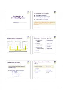
fmssup Supervisor Emulator Control Hierarchy fmscell
cellmhs
pc1cell
pc1mhs
mhsplc
pc1proc
pc1plc
pc2cell
pc2mhs
pc2proc
pc2plc
pc3cell
pc3mhs
pc3proc
pc3plc
fscell
pc4cell
pc4mhs pc4proc
pc4plc
fsmhs
fsproc1
fsproc2
fsplc Physical Equiptmemt
Figure 1. The hierarchical architecture used in our physical emulator
THE CONCEPTS Davis (1992) [3], Davis et al. (1993) [4], Davis et al. (1996 and 1997) [5] and [6], and Gonzalez and Davis (1999) [16] present a solution to this problem by developing a conceptual framework for the intelligent control of flexible manufacturing systems and other distributed DESs. Our conceptual framework can be summarized into three fundamental concepts: The Hierarchical Architecture, which provides a means for defining the component subsystems making up the overall system, The Simulation of Distributed Systems which allows the use of distributed models by taking into consideration the interactions among the distributed controllers into the simulation, and The Intelligent Cell Controller which provides the generic framework for the intelligent controller that is contained within each subsystem. The following section describes the first two concepts. The intelligent cell controller is not presented here since it is not within the scope of this paper. This section is described in Gonzalez (2003) [11] and Gonzalez and Davis (1999) [16].
The Hierarchical Architecture The concept of the Hierarchical Architecture was originally published in Tirpak et al. (1992) [25]. The architecture introduces the coordinated object, CO, as the basic element for modeling an FMS or other DESs. Each coordinated object represents a basic hierarchical element where intelligent control or integrated planning and control are to be addressed. In Figure 1 an example hierarchy is shown. Using this architecture gives rise to multiresolutional control. At the top most level, the coordinated object's scope of control includes the most aggregate level of decision. The planning horizon may be very long perhaps looking several months or years ahead. This coordinated object makes high level decisions. This object can be thought of as the CEO of a
company. The controller in the middle levels have a smaller planning horizon but are still making managerial type decision. These objects are similar to the middle level managers at a company. At the bottom most level, the controller has the smallest planning horizon and is limited to the most immediate concerns. These decisions are primarily concerned with the adjustment of machine-related parameters such as the speed of a certain motor or the amount of pressure at a valve. These objects are similar to the factory workers at a company.
The Distributed Modeling Methodology The simulation of distributed systems discussed here is based on the distributed modeling methodology referred to as Hierarchical Object Oriented Programmable Logic Simulator (HOOPLS) in the following references, Davis et. al. (1997) [6], Davis et. al. (1993) [9] and Davis (1998) [7]. This methodology is based upon the belief that the interactions among the controllers must be considered by the simulation model in order to accurately model a system with a distributed control architecture. The single most important characteristic of the methodology and what separates it from other object-oriented simulation approaches is its attention to modeling the flow of messages among the controllers included within the architecture. By modeling the flow of messages, the methodology allows the simulation to accommodate distributed models. This has many advantages: 1.
The simulation is more accurate since it includes all of the communication among the distributed controllers.
2.
The simulation produces maximum fidelity since the same model is used for both simulation and control.
3.
4.
The modeling effort is shared between control and simulation. They both share the same models. The control and simulation models necessarily employ the same state definition. This simplifies the task of initializing the simulation model to the current system-state. If the simulation and control models employ different state definitions, which is the usual case when one employs conventional simulation approaches, then one must translate the measured system variables into values for the state variable employed within the
simulation model. See Gonzalez and Davis (1998) [15]. 5.
This methodology offers multi-resolutional modeling for simulation. Since the system models have a hierarchical organization, the simulation resolution can be dynamically selected by selecting the levels in the hierarchy to include models for.
THE IMPLEMENTATION The best way to present our methodology is by describing the implementation of our simulation and control tool that is build around this methodology. The basic process for implementing our tool consists of first implementing the simple single-model simulation as an object and then including all of these objects, each with its own model, into a single program. The coordinating function implements the multitasking operation by allocating the CPU to the objects in a manner that provides a chronologically correct sequence of operations among the individual simulation objects. The coordination function does this by simulating the communication network and managing the flow of messages from one object to the next.
The Modeling Framework Each individual simulation is represented as an object in C++. As with most simulation approaches, this approach is also event-driven, and an executive function manages the simulation by the sequential processing of events. Two event lists are maintained where the events are stored waiting to be executed at the right time. Our simulation tool, like most simulation tools, consists of three basic parts. 1.
The executive function, which actually runs the simulation under the constraints of the system model.
2.
The data structures, which include the event list, (a list of events scheduled to occur in the future); the pending event list, (a list of events awaiting a response from the hardware to occur before they can be processed); and the resource list.
3.
The set of modeling elements that are used to build the system model.
The simulation object contains all of the data structures, the executive function and a pointer to the model and to the communication function. The
executive function manages the chronologically ordered event list, the pending event list, controls the processing of the events as they are removed from the event list, schedules new events to be placed upon the scheduled event or pending event list, and manages the allocation of resources. From here on we will refer to the event list as the scheduled event list to distinguish it from the pending event list. The simulation object is called this way since it is the way simulation is typically written. Even though we use this object for control we still call it the simulation object. It is assumed that this object is used to control the system components.
The System Model The system model for our tool plays the same role and is written in the same fashion and with the same modeling elements as a typical commercial simulation program such as Arena by Rockwell Software, Kelton (2001) [19]. This model must be provided to the simulation object, see Figure 2, by the user and specifies the actions that must occur to execute the events as they occur. The object stores the address of this function so it can call it during execution. In our tool the system model may be implemented as a large case statement or switch statement with the event number being the variable in the switch. This makes the model be a list of events and is similar to the way models are built in Arena. Its primary advantage is that the sequence of logic is easy to see. An object oriented approach may be use as well depending on the user’s preference. The model function simply executes a segment of code corresponding to the event number passed to it. The execution of that segment of code models the actions taken by the system’s controller when that event actually occurs during the execution in the real system. Modeling elements are used to write these code segments. These modeling elements includes CREATE, DELAY, QUESEIZE, RELEASE, and SEIZE for the basic modeling, PENDING and INPUT for control, TALLY for gathering statistical data, and ERROR and TIMEOUT for error handling while in control mode. Other modeling elements such as DISPOSE, DECIDE and so on are not implemented because they ca n be trivially implemented in C. The user must also supply the communication function to the executive object if running in control mode. This function handles all of the communications among the distributed controllers and the actual machines. The simulation object can run in two modes. In simulation mode, the system clock advances in discrete increments. Every time an event is pulled off of the scheduled event list, the time is incremented to the event’s time of occurrence.
Figure 2. The executive object. Note the circles represent objects, while the squares represent functions and the flat rectangles represent pointer variables No hardware is present. The system is purely a software program. While in control mode, the system clock runs in real time. That is, the system clock is a real clock like the one on the wall. Time advances continuously. Events are pulled off of the scheduled event list when their event time occurs. Hardware may be present. The pending event list is used to allow the hardware to determine when events occur. The events in this list do not have a time associated with them. They are in effect pending. The models are constructed using modeling elements. These elements acts as function call to the simulation engine and are used to perform simulation activities such as scheduling events or allocating resources. For a complete list of modeling elements and more detail of there usage see Gonzalez and Davis (2002) [17] or Gonzalez and Davis (1997) [13].
The Implementation of the Coordinating Function Now that we understand the basic structure of our tool we can present our methodology. The following section describes how the distributed simulation was implemented. This section discusses the features that are available in the simulation software that allow distributed simulation. These features along with a function that ties all of the distributed models together referred to as the coordinating function permit the simulation of distributed systems. Note, although the simulation is simulating a distributed system, the simulation itself is not distributed.
The executive function of the simulation object has certain features that allow it to simulate distributed systems. First each individual simulation is totally performed by the executive function of that object. Since the executive function, its data structures and the pointers to the user supplied functions are encapsulated into an abject one can include several instantiations of this object into a single program. This is needed since a distributed system is composed of several independent controllers. To build the simulation one simply includes all of these simulation objects into a single program without concern to duplicate variable and function names. Obviously all of the simulation objects can not run at the same time. Since there is only one thread in a program only one object can be executed at any given time. The next feature provides a method of multitasking that guarantees the correct sequential order of execution of events without wasting any CPU time. Because there are several instantiations of the simulation executive function within the distributed simulation, the executive functions cannot continuously cycle through the loop. The executive functions are modified so that it only cycles through the loop once every time it is called. It does not check the communication lines at the end of the cycle either since by definition the system is in simulation mode. While there is communication between the simulation objects, they do not involve the network (there are no TCP/IP sockets involved). All communication is handled by the message relay. The coordination function does not execute any part of the simulation, it simply calls the executive function of the model that will execute the next event. At this time, the model’s own executive function cycles through the loop once, executing the events, before giving control back to the coordination function. Another feature addresses the manner in which messages enter the model. Instead of checking the communication lines every time the executive function reaches the end of a cycle, the lines are not checked at all. The coordination function manages the flow of messages, instead. Whenever a message is present, the coordination function calls the executive function of the appropriate submodel’s object and gives it the message. The executive function will then handle the message in the same way it previously handled messages when it was detecting their arrival. The last feature in the simulation software is the DELAY block. When a DELAY block is executed, in addition to scheduling a DELAY event onto the submodel’s scheduled event list, it also schedules an
event into the coordination function’s global event list as well. This method maintains the global event list that the coordination function needs to know which object to give the processor to next. The modeler does not consider this event list when modeling a local delay. From the user’s point of view, the delay is modeled in the same way as if the model is not distributed. This is one of the nice features about this method. The user writes the model in the same fashion as is traditionally done with a single model. No need to do things differently to accommodate our method.
The Coordination Function The coordination function consists of a global scheduled event list and the message relay. When a submodel’s object is being executed, the message relay receives all of the messages that are output by the simulation object that is currently running. The messages are stored into the rear of the message queue, which is used to implement the message relay. Once the simulation object finishes its execution, the coordination function removes the message that is at the front of the message queue and gives it to the recipient simulation object. Some other simulation object receives the message and executes the appropriate functions to handle the message. Further messages may be generated by the execution of that event. These messages are also inserted into the rear of the message queue. Once control is given back to the coordination function, it removes the next message at the front of the message queue and recycles it though the loop. This is repeated until there are no more messages in the queue. If one wants to model a delay to represent the transmission time for the message, then this can be incorporated into the model by executing a delay event each time a message is received. As illustrated in Figure 3, the coordinating executive function starts its cycle and removes the next event, the one occurring in controller number 3, from the global event list. It gives the processor to simulation object number 3. Object 3 executes this event and as a result of its modeling logic it sends a message to object number 2. This message is sent to the message relay that simulates the network. Once object 3 completes its cycle it relinquishes control back to the coordinating function. The coordinating function then removes the next message from the message queue and delivers it to the proper recipient, object 2 in this case. Next object 2 receives this message and executes the appropriate event. In the execution of this event, controller number 2 schedules a new event onto its local event list and a copy is scheduled onto the global event list. At this point, the event-execution cycle of the coordinating
function terminates and the function removes the next event from the global event list and begins a new eventexecution cycle. Global Event List
simulations using a slightly different set of models. However this does not represent any extra effort since in our tool, creating the simulation model only involves selecting models from the pool of models that are used for control. The modeling effort is in fact shared between control and simulation.
1 Message Relay
2
3
Figure 4. Diagram of 3 distributed controllers. Controller 2 and 3 are at the bottom layer while controller 1 is the supervisor. Controller 1 is executing a simulation consisting of the 3 models Figure 3. An example of a simulation of a controller decomposed into three subcontrollers. Note the separation of the message relay and the global event list. Each of the three subcontrollers is simply included into the simulation without any modification
THE OVERALL IMPLEMENTATION This section describes how the overall system works. The physical system is decomposed into small components forming a hierarchy as described by our hierarchical architecture. For each component a model is written to describe its operation and a communication function is written as well. The communication function will probably be very similar for each component. To control the system a simulation object running in control mode is created for each component and executes the component’s model. See Figure 4. Simulation of the distributed system is required to support the decision making process that takes place in each controller. Therefore each controller needs to have a simulation model that represents the system its controlling. This includes its own model as well as the models for the subordinate controllers that are in its control domain. How many levels down the hierarchy are included in the models depends on the desired resolution. Since each controller is in a different location in the hierarchy each controller will perform
To simulate the distributed system first an appropriate set of models are collected. This set may include a model for each component that is in the control domain of the component using the simulation. It’s a subset of the whole collection of models. A simulation object is created for each model and included in a program along with a copy of the coordinating function. Using the control model for simulation yields the maximum fidelity. The simulation performs exactly as the controllers do since the same model governs them. The objects are then run in simulation mode and the coordinating function runs the simulation as described above. In addition to coordinating the objects, simulating the network also adds fidelity. The message flow that occurs between the independent controllers is in effect represented in our simulation even though no direct modeling of the network appears in any of the models. Incidentally this was the original incentive in developing this methodology. When the simulation begins the current state is gathered. The coordination function asks each controller in its control domain to provide its current state. This state is simply the data in the variables and data structures of the object plus a few from the model itself. The coordination function then initializes each object by giving it the corresponding state. Since the
objects are simply copies of the objects used for control they have exactly the same variables and data structures. Therefore to initialize the models, the contents of the controlling object’s variables and data structures (the state) is copied into the simulation object without any interpretation or translation. It is not necessary to know the meaning of this data. This is a major advantage since without our method one will have to translate the state information from the control model to the simulation model. This involves understanding the meaning of all of the data in the variables and data structures of the controlling model. This is a very difficult task that is totally eliminated using our method. Our tool has been used to implement a controller for a physical emulator, see Gonzalez and Davis (1998) [14] and Gonzalez et. al. (2000) [18]. The comptroller consisted of 25 independent controllers each with it’s own model. Real-time simulations of the distributed controller using our methodology were concurrently executed along with the controller that controlled the physical emulator using the same simulation model. The simulations were initialized to the current state of the physical emulator before starting. The simulation includes all 25 models. The results were compared to the actual results obtained from the physical emulator. Differences in the results were so small that it is believed that it is only due to the randomness of the simulation. Unfortunately we were not able to collect good data because the emulator was not reliable and it would not run for more than about 30 minutes. We are currently working on a new solid state emulator that will be sufficiently reliable to run for months at a time. See Davis et al. (1994) [8] and Gonzalez et al.(1997) [12].
CONCLUSION AND FUTURE WORK We have shown a method for modeling discrete-event systems using a collection of independent models. In order to simulate a distributed discrete-event system with a non-distributed simulation, several features must be present in a simulation tool. The first is the capability of including several simulation objects into a single program. This is accomplished by enclosing the simulation tool into an object so that several instantiations of the tool can exist in a single program. The second feature that a simulation tool must have is the capability to execute only one event along with the events that immediately occur as a reaction to the occurrence of the event before returning control back to the supervisory process.
We have described a simulation tool written in C++ having these features. We presented a supervisory function called the coordination function that, when used in conjunction with the distributed models created under our simulation tool, permits the simulation of a distributed system. The next step in this research is to develop the intelligence that will perform the real-time scheduling and control functions for each control object. Our immediate research plans will address the development of a real-time scheduling capability for the cell controller.
REFERENCES [1]
[2]
[3]
[4]
[5]
[6]
[7]
G. Arango and R. Prieto-Diaz, 1991. “Domain analysis: concepts and research directions,” Domain Analysis and Software Systems Modeling, Los Alamitos, CA: IEEE Computer Society Press, pp. 9-33. D. A. Bodner, S. A. Reveliotis, 1997. “Virtual factories: an object-oriented simulation-based framework for real-time FMS control,” Proceedings of the 6th International Conference on Emerging Technologies and Factory Automation, pp. 208 –213. W. J. Davis, 1992. “A concurrent computing algorithm for real-time decision making,” ORSA Computer Science and Operation Research: New Developments in their Interfaces Conference, Jan. 8-10, pp. 247-266. W. J. Davis, D. Setterdahl, J. Macro, V. Izokaitis, and B. Bauman, 1993. “Recent Advances in the Modeling, Scheduling and Control of Flexible Automation,” Proceedings of the 1993 Winter Simulation Conference, pp. 143155. W. J. Davis, J. G. Macro, A. L. Brooks, M. S. Lee, G. S. Zhou, 1996. "Developing a real-time emulation of multiresolutional control architectures for complex, discrete-event systems," Proceedings of the Second Semiotic Modeling and Simulation Analysis Conference, National Institute of Standards and Technology October 20-23, pp. 274-279. W. J. Davis, J. Macro, and D. Setterdahl, 1997. "An Integrated Methodology for the Modeling, Scheduling and Control of Flexible Automation," Journal on Robotics and Intelligent Control. W. J. Davis, 1998. “On-Line Simulation: Need and Evolving Research Requirements,” in Simulation Handbook, J. Banks, ed., Wiley, pp. 465-516.
[8]
[9]
[10]
[11]
[12]
[13]
[14]
[15]
[16]
W. J. Davis, B. Bauman, J. Macro, and D. Setterdahl, 1994. “Constructing an Emulator for Research and Education in the Control of Flexible Automation,” in Proceedings of the ORSA Technical Section on Manufacturing Management Conference., eds. J. Buzacott and C.A. Yano, pp. 151-157. W. J. Davis, D. Setterdahl, J. Macro, V. Izokaitis, and B. Bauman, 1993. “Recent Advances in the Modeling, Scheduling and Control of Flexible Automation,” Proceedings of the 1993 Winter Simulation Conference, pp. 143155. T. Govindaraj, L. F. McGinnis, C. M. Mitchell, D. A. Bodner, S. Narayanan and U. Sreekanth, 1993. “OOSIM: A Tool for Simulating Modern Manufacturing Systems,” Proceedings of the 1993 National Science Foundation Grantees in Design and Manufacturing Conference, pp. 1055-1062. F. G. Gonzalez, 2003. “Intelligent Control of Distributed Large Scale Manufacturing Systems,” Proceedings of the 2003 National Science Foundation Design, Service and Manufacture and Industrial Innovation Grantees and Research Conference. F. G. Gonzalez, W. J. Davis, 1997. "A Simulation-Based Controller for Distributed Discrete-Event Systems with Application to Flexible Manufacturing," Proceedings of the 1997 Winter Simulation Conference, pp. 845853. F. G. Gonzalez, W. J. Davis, 1997. "A simulation-based controller for a flexible manufacturing cell," Proceedings of the 1997 International Conference on Systems, Man and Cybernetics. F. G. Gonzalez, W. J. Davis, 1998. "Developing a Physical Emulator for a Flexible Manufacturing System," Proceedings of the 1998 International Conference on Systems, Man and Cybernetics. F. G. Gonzalez, W. J. Davis, 1998. "Initializing On-Line Simulations From the State of a Distributed System," Proceedings of the 1998 Winter Simulation Conference. F. G. Gonzalez, W. J. Davis, 1999. "An Intelligent Control Architecture Distributed Across The Network, For The Control Of LargeScale Discrete-Event System," proceedings of the 1999 joint conference of the Third World Multiconference on System, Cybernetics and Informatics (SCI 99) and the Fifth International
[17]
[18]
[19] [20]
[21]
[22]
[23]
[24]
[25]
Conference on Information Systems Analysis and Synthesis (ISAS 99). F. G. Gonzalez, W. J. Davis, 2002. "A New Simulation Tool for the Modeling and Control of Distributed Systems," To appear in SIMULATION The Journal of the Society for Computer Simulation International. F. G. Gonzalez, A. Helton, D. Helton, J. Smith, E. Thompson, G. Walterscheild, 2000. "The Design of a Solid-State Physical Model of an Automated System to be used as a Test Bed for Control Applications," Proceedings of the 2000 Winter Simulation Conference. W. D. Kelton, R. P. Sadowski, and D. A. Sadowski, 2001. Simulation with ARENA, McGraw-Hill, 2nd ed. S. D. Narayanan, A. Bodner, U. Sreekanth, S. J. Dilley, T. Govindaraj, L. F. McGinnis and C. M. Mitchell, 1992. "Object-Oriented Simulation to Support Operator Decision Making in Semiconductor Manufacturing," Proceedings of the 1992 International Conference on Systems, Man and Cybernetics, pp. 1510-1519. B. A. Peters, J. S. Smith, J. Curry and C. LaJimodiere, 1996. “Advanced Tutorial Simulation Based Scheduling and Control,” Proceedings of the 1996 Winter Simulation Conference, Eds. J. M. Charnes, D. J. Morrice, D. T. Brunner and J. J. Swain, pp. 194-198. J. S. Smith, R. A. Wysk, D. T. Sturrock, S. E. Ramaswamy, G. D. Smith and S. B. Joshi, 1994. “Discrete Event Simulation for Shop Floor Control,” Proceedings of the 1994 Winter Simulation Conference, pp. 962-969. J. S. Smith, B. A. Peters, 1998. “Simulation as a decision-making tool for real-time control of flexible manufacturing systems,” Proceedings of the 1998 International Conference on Robotics and Automation, pp. 586-590. K. E. Stecke, 1985. “Design, planning Scheduling and Control problems of flexible manufacturing systems,” Annals of Operation Research, vol. 3, T. M. Tirpak, S. M. Daniel, J. D. LaLonde, and W. J. Davis, 1992. "A Fractal Architecture for Modeling and Controlling Flexible Manufacturing Systems," IEEE Transactions on Systems, Man and Cybernetics, 22(5), 1992, 564567.