Abstract. We present a simulation for endoscopic procedures. The ana- tomy of the patient is represented by 3D polyhedral models, computed from tomographic ...
Simulation of Endoscopy
?
Bernhard Geiger1 and Ron Kikinis2 Institut National de Recherche en Informatique et Automatique BP 93 { 06902 Sophia Antipolis Cedex, (France) Dept. of Radiology, Harvard Medical School and Brigham and Women's Hospital Boston MA 1
2
Abstract. We present a simulation for endoscopic procedures. The anatomy of the patient is represented by 3D polyhedral models, computed from tomographic images. The simulation program can be used as a training system, or for prior simulation of complicated individual cases to reduce the error rate and to decide on the feasibility of biopsies. Additionally, we show how the system could be used as an online monitor during the intervention without the use of external tracking devices. The parameters used are the inserted length and the axis-orientation of the endoscope. An example of a bronchoscopy is shown.
1 Introduction Minimally invasive procedures like endoscopy and laparascopy play an increasing role in interventional treatment. Modern endoscopic devices are exible tubes that are inserted into body cavities and the interior of hollow organs. They are equipped with an optical channel that transmits an image to a video display. One typical task is to reach a tumor and perform a biopsy. This implies: { a navigation problem: The exact position and orientation of the device is not easily determinable from the local view, especially in a branching organ. { a visual problem: The tumor may be visible on CT or MRI, but not on the endoscopic surface view, if the wall is not directly a�ected. { a veri cation problem: We want to know if the whole surface of the organ has been inspected. Therefore it is desirable to provide a global view of the region showing the hollow organ, the exact position of the endoscope and the target (tumor). While the nal goal is to have this information available in real time during the intervention, we propose as a rst step an o�ine simulation on a computerized 3D model. This permits the procedure to be conducted beforehand, determining parameters like the choice of branches and the length of the trajectory. Such a simulation may also reveal whether the endoscope can reach the target or not, due to an incompatibility between the diameters of the endoscope and the conduit. Furthermore, we show that in a tree structure like the respiratory system, it is possible to determine the position of the endoscope if the inserted length and ?
This work was supported in part by ESPRIT III Bra Project (PROmotion 6546)
the axis orientation are provided in addition to the video image. This paper is organized as follows: { We show how to calculate a 3D model of the organs of interest from spiral CT images, { We de ne a simple physical and optical model of the endoscope { We show a method to automatically calculate the camera trajectory. { We propose a method to detect the endoscope's position online.
2 Geometric modeling The Delaunay reconstruction can be used to obtain both a volume and a surface representation from contours distributed on parallel cross-sections [2, 1]. This method is based on geometric closeness. It is a simple heuristic method, similar to that of the voxel technique. However, the volume elements are not equally shaped, but consist of tetrahedra that are adapted to the object shape. The advantages of this method are as follows: { It gets directly to a 3D polyhedral representation composed of tetrahedra. The surface is a subset of the tetrahedra faces. { The property of connecting contours on adjacent planes by triangles avoids the need for anti-aliasing or interpolation steps, especially for large crosssection distances (anisotropic sampling). { Complex contours with multiple branchings, birth and death of holes, and complicated splitting lines, are all handled correctly. { We get a considerable reduction in data compared to other volume oriented methods. Real time display of reconstructed human organs is therefore possible on standard graphics workstations. { The tetrahedral structure is appropriate for applications like simulation of motion or nite element methods.
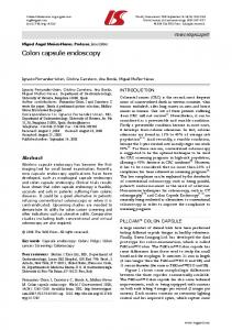
3 Physical model of the endoscope We use a very simple model of an endoscope. The camera is represented by a cylindrical object. The viewing direction is the longitudinal axis (z-axis). The camera has three functions simulating the properties of a real endoscope: { go forwards/backwards in the direction of the z-axis { turn around its z-axis by -180|180 deg { pivot around the x-axis by -90|90 deg If the camera hits the wall, we calculate the force and moment and then produce small corrective motions to reduce the forces to zero3 . The allowed motions are rotations around the x- and y- axes and translations orthogonal to the z-axis of the camera (see Fig. 1). Due to the geometry of the camera, it usually turns 3
Details on the intersection test and force calculation can be found in [2]
F
z y x
Fig. 1. Avoiding a penetration of the wall
4 Trajectory calculation
its z-axis parallel to the conduit. If the camera size is chosen according to the actual diameter of the endoscope, the force minimization loop gives a response as to whether the endoscopy can pass or whether it would get stuck in a small branch. In this rst approach, we did not try to de ne a more complex model, and in particular we did dot build a complete exible chain. However our simple model turns out to be a good approximation.
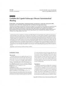
Besides the possibility of reaching a target by using the above functions repeatedly, we also provide a method of calculating a trajectory automatically. The user can specify the target point interactively. We can rapidly nd the tetrahedron containing the current camera position and the tetrahedron containing the target point. Then we search for a set of tetrahedra connected face to face and linking with . We then connect with by a straight line segment , and verify that it lies completely inside the trachea tetrahedra. If not, we choose a tetrahedron from the middle of and replace by two segments 1 connecting and and 2 connecting and . This procedure is repeated recursively until all segments are inside the trachea. When the camera nally follows this trajectory, we detect an eventual penetration of the wall and modify the trajectory. At this stage, we can also detect if the diameter of the conduit is adequate for the endoscope. This procedure does not necessarily provide the closest path. C
T
S
C
T
C
T
s
M
S
C
M
s
M
s
C
C
z
s
T
T
T
Fig. 2. Automatic calculation of the endoscope trajectory
5 Experimental Results We implemented this system on a Silicon Graphics workstation (Indy) using the SGI graphics library gl. Three windows are displayed: The global view, the local view and the nearest CT slice with the camera position indicated. The global view shows the model of the organ, the target and the endoscope. The scene can be viewed from any angle, and details can be zoomed in. The local
Fig. 3. A biopsy of a lung tumor. The local view (top left) the closest CT image
(top right) and the global view (below). view is the endoscopic surface view. We use the same model as for the global view, but place the viewpoint in the tip of the endoscope (see Fig. 3). We run the simulation with several datasets: lungs, sinus, brain ventricles and colon, all obtained from spiral CT acquisitions. While the sinus data was successfully segmented by simple thresholding (air), we used statistical segmentation and interactive editing in the other cases. The example in Fig. 3 has been manually segmented to add the smaller bronchi. A typical model consists of about 60000 tetrahedra and 5000 surface triangles. The time for calculating the contact between surface and camera is clearly inferior to the display time. On a Silicon Graphics Indy with an MIPS R4400 processor chip (no hardware rendering) we obtained a rate of about one frame per second. This model can be improved by mapping texture onto the walls, using advanced lighting models, and adding gravitational forces to the camera model.
6 Online tracking of the endoscope position Given a path-length in a tree-like structure, there is only a discrete set of points where the camera may be found. If the endoscope could be equipped with a device measuring both the inserted length and the endoscope's rotation around its axis, we might be able to calculate its exact position in the model [4]. The inserted length and rotational values could be obtained for example by measuring the remaining part and the orientation relatively to the patients teeth. The crucial points would then be the branchings, and we must provide a way of automatically deciding which branch the endoscope took. We can think of two complementary ways: Firstly, if the endoscope approaches a branching, we can generate two series of synthetic images inside the model, one showing the local image when taking one branch, and the other showing the local image taking the other. By correlating the synthetic images with the real video images, we may then nd out the correct branch. Secondly, a path in a tree may be represented by the sum of the distances between the nodes. A node may be represented by a vector = ( 1 2 i ) where 1 to i are the distances between the nodes that have been passed. If we are able to automatically detect branchings on the real video image, we can, by comparing this vector to all possible vectors, determine the closest match and therefore the exact position, given that the tree is su�ciently asymmetrical. This second method may be employed complementarily to the rst one. Since the range of a CT acquisition never shows the teeth, the endoscope length has to be initialized to 0 at a characteristic position, like the branching of the trachea into the two main bronchi (carina). l
l
l
l ; l ; : : :l
i
Acknowledgement We are grateful to Olivier Dourthe for providing the CT images of the lung.
References 1. J-D. Boissonnat and B. Geiger. Three dimensional reconstruction of complex shapes based on the Delaunay triangulation. In R. S. Acharya and D. B. Goldgof, editors, Biomedical Image Processing and Biomedical Visualization,volume 1905, pages 964{ 975. SPIE, 1993. 2. B. Geiger. Three-dimensional modeling of human organs and its application to diagnosis and surgical planning. Report 2105, INRIA Sophia-Antipolis, Valbonne, France, 1993. 3. B. Geiger and R. Kikinis. Simulation of endoscopy. In AAAI Spring Symposium Series: Applications of Computer Vision in Medical Images Processing, pages 138{ 140, Stanford University, 1994. 4. W.M. Wells III. Personal communication. 5. J Toriwaki. Study of computer diagnosis of X-ray and CT images in Japan - a brief survey. In IEEE Workshop on Biomedical Image Analysis, pages 155{164. IEEE Computer Society Press, 1994.