Int. Journal of Applied IT Vol. 01 No. 02 (2017)
International Journal of Applied Information Technology http://journals.telkomuniversity.ac.id/ijait
Simulation of Memory-Based 1024-Point Fast Fourier Transform for Broadband Wireless Access Technology on FPGA Dinda Pramanta a, Denny Darlis b, *, Iswahyudi Hidayat c b
Diploma of Telecommunication Engineering, Telkom University, Indonesia Electrical Engineering, Telkom University, Indonesia
a,c
ARTICLE INFO
ABSTRACT
Received June 7, 2017 Revised July 24, 2017 Accepted August 8, 2017 Available online August 14, 2017
The limited radio frequency spectrum that can be used for transmission leads to bandwidth and power efficiency being a key requirement in the development of wireless access technology from 3G to 5G today. Data communication technology also requires this as mentioned on high speed network standards such as DSL, WLAN and WMAN with its products ADSL, WiFi and Wimax. In the last few decades we have seen the evolution of the Orthogonal Frequency Division Multiplexing (OFDM) modulation technique used in the technologies mentioned earlier to this day. This technique is regarded as a standard technology for broadband wireless access technology. In hardware implementation, the most preferred by many researchers is the Field Programmable Gate Array chip, as it can be reconfigured. The OFDM technique can be easily implemented because it uses Fast Fourier Transform (FFT) algorithms that are coding and programming capable of reducing the computational time of Discrete Fourier Transform. This paper discusses the implementation of the memory-based 1024-point IFFT / FFT for BWA communications. The design is focused on synthesizing and implementing the system block FFT 1024-point radix-4 using Decimation in Frequency (DIF) method. Implementation for IFFT / FFT 1024-point resource usage slice number 1%, the number of slice flip-flop 1%, the number 4 LUT (Look Up Table) 1%, and the number of IOB 27%. of the FPGA are used.
Keywords BWA, FFT, FPGA, VHDL
* Corresponding author at: Diploma of Telecommunication Engineering, Telkom University, Jl. Telekomunikasi No. 1, Terusan Buah Batu, Bandung, 40257 Indonesia. E-mail address:
[email protected] ORCID ID: Second Author: 0000-0001-9242-9522
DOI will be updated when available. Paper registration number IJAIT000010204 2017 © The Authors. Published by School of Applied Science, Telkom University. This is an open access article under the CC BY-NC license (https://creativecommons.org/licenses/by-nc/4.0/).
Int. Journal of Applied IT Vol. 01 No. 02 (2017)
1. Introduction Digital communication has grown so rapidly along with the growth and development of the era of computerization and telecommunications. To facilitate the integration of reliable telecommunications systems, digital communication has many advantages more than the analog communication such as the generation of reset signals is much easier, more resistant to distortion and interference, as well as smaller error rate number. The current BWA standards can now be operated and is widely used standards issued by the Institute of Electrical and Electronics Engineering (IEEE), such as the 802.15 standard for Personal Area Network (PAN), 802.11 for Wireless Fidelity networks (Wi-Fi), and 802.16 for the network WiMAX. WiMAX is a broadband solution to blank spot address areas. WiMAX technology for broadband services is not only used as a fixed but also mobile access that has speeds up to 70 Mbps. OFDM is an access method that is used or applied to BWA. This technique first applied on wireline technology such as ADSL and Broadband Powerline [1]. OFDM has become the preferred modulation scheme for spectral efficiency and robustness against various interferences in wireless technology such as mention above [3,5]. Although the components and the overall structure are different, OFDM protocols are functionally similar [6]. FFT block is an important part of an OFDM, because the process of sharing the high-speed data stream into several low speed sub stream underway [8]. This division process aims to provide high efficiency in the use of the frequency spectrum. Therefore, the ability of sending and receiving data on the process of communication depends on the performance of the FFT processor [2,4]. In this research, a VHDL-based FFT 1024 points using the radix-4 as the basis for calculation has been designed. By using the Cooley-Tukey algorithm, the calculation of the DFT on which the basic implementation of FFT on FPGA becoming fewer and simpler so that the process is faster and require less memory than using the usual FFT transformation [7]. The calculation complexities of FFT make a huge manufacturing cost in a hardware application. Therefore, in this research, the process of calculating the FFT 1024-point radix-4 performed using the Cooley-Tukey algorithm by using Xilinx Virtex-4 XCVLX25, so it can be easier for us when designing and implementing it on FPGA board.
2. Theoretical Background 2.1. Orthogonal Frequency Division Multiplexing Orthogonal Frequency Division Multiplexing (OFDM) modulation technique known as commonly used in the wireless channel that always changing due to fading. When information is transmitted over the wireless channel, the signal may be distorted due to multipath fading. Unlike single carrier systems, OFDM communication system does not rely on an increase in symbol rate to achieve a higher data rate. This makes the Inter Symbol Interference (ISI) task becomes easier, because the data is transmitted in parallel would be better than the series, then the symbol of the OFDM symbol is longer than a single carrier with a data rate that is commensurate. In addition to providing the advantages, OFDM has two relative susceptibilities to the single carrier system, which is a weakness of the error signal carrier frequency and the extent of peak-to-average power ratio (PAPR) [4].
29
30
Int. Journal of Applied IT Vol. 01 No. 02 (2017)
2.2. FFT Radix-4 [12] FFT to calculate the DFT by reducing the number of calculations and leaving direct DFT calculation. However, this requires additional steps for the preparation of the data back, to determine the result. However, the additional steps will not add a significant step in the computational complexity of the calculations, as it is implemented efficiently. As a result, the FFT is a very efficient way that produces the best implementation in hardware. As mentioned above, the general equation of the FFT is: X[k] = ∑ where
[ ].
;
= 0,1,2, … ,
− 1 .................................................(1)
referred to twiddle factor that has the value
X[k] = ∑
[ ].
;
= 0,1,2, … ,
, with the result that:
− 1 ...............................................(2)
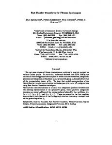
Accordingly, for a 4-point FFT we can do a simple calculation, using the Decimation in frequency (DIF). On the basis of the above calculation, we can perform calculations with a larger 4-point as radix which is for 1024 points using the radix-4 which requires 5 steps (1024 = 45) as shown in Figure 1 for 16 point FFT. The application of the most widely used for this equation is the signal analysis. Signal x(n) is the signal being analyzed, amounting to N points. Signal x(n) is the signal cycle length N 1 point. DFT of x (n) produces x (k). At k = 1, | x (k) | has a high peak, meaning that x (n) has an element of one cycle per frequency component N points. In addition, at k = N-1, other peaks were observed. Output Npoint DFT has a characteristic cycle.
Figure 1 DFT Radix-4 with 16 Point. [9-12]
Then, the index k = N-1 so that k = -1, the negative frequency. Since the signal x (n) consists of frequency components k = 1 (positive) and k = -1 (negative), then the components of x (k) has a component k-1 and k = -1.
3. Design and Simulation 3.1. Design of Memory-based 1024-point FFT Radix-4 Designing 1024 point FFT is using the FFT algorithm 4-points or more commonly known as algorithm radix-4. Designing is done in several stages as
Int. Journal of Applied IT Vol. 01 No. 02 (2017)
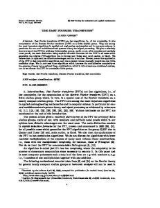
shown on Figure 2. First, the mathematical calculation of FFT 1024 point using radix-4 algorithm to realize the designed block diagram [10].
Figure 2 Design Flow Diagram for Simulation of 1024-Point FFT
The next stage is simulation using MATLAB that can be tested on mathematical calculations and algorithms that have been specified. MATLAB output will then be used as a comparison to the output encoding is done in ModelSim VHDL language. Elaboration about the stages of 1024 point FFT is described as follow. 1.
Step 1; By defining X1 variable as the result of FFT calculation on the first stage, then from the equation (3) obtained:
31
32
Int. Journal of Applied IT Vol. 01 No. 02 (2017)
1( 0
+4
1
+ 16
2
+ 64
3
+ 256
0)
=
Multiplication with twiddle factor
64 3 0 1024
64 3 0 1024
∑34 =0 ( )
256 4 0 ..(3) 1024
is a type of non-trivial
multiplication. Twiddle factor can be simplified to 163 0 , then obtaining 16 complex value twiddle costants. This value then is translated into the value of sine and cosine and then stored in the ROM. 2.
(
+4
)
256
+ 16
Step 2; By defining the variable X2 as a result of the second stage of the FFT calculation for the value n_3=0,1,2,3 then obtained:
+ 64
+ 256
)=
∑
(
+4
+ 16
+ 64
+
…………………………………………………………………………………….(4) Nontrivial multiplication re-acquired at multiplication with twiddle factor 256 3 1 and 1024
by elaborating twiddle factor, will be obtained 15 twiddle constant for non-trivial multiplication. In line with the previous stage, the twiddle constants stored in ROM. 3.
(
+4
)
256
+ 16
Step 3; By defining the variable X3 as a result of the third stage of the FFT calculation for the value n_2=0,1,2,3 then obtained:
+ 64
+ 256
)=
∑
(
+4
+ 16
+ 64
+
……………………………………………………………………………………(5) Nontrivial multiplication re-acquired at multiplication with twiddle factor 256 2 2 1024
and by elaborating twiddle factor, will be obtained 63 twiddle constant for non-trivial multiplication. In line with the previous stage, the twiddle constants stored in ROM. 4.
4( 0
16
2
+4
+ 64
3
1
+ 16
2
+ 256
Step 4; By defining the variable X4 as a result of the fourth stage of the FFT calculation for the value n_1=0,1,2,3 then obtained : 4 0 1 16 0 2 64 0 3 3 0 0 1 + 256 0 ) = 1024 1024 1024 1024 ∑ 1 =0 3 ( 0 + 4 1 256 1 3 ………………………………………………………..... 1024
+ 64
0)
+
(6)
Nontrivial multiplication re-acquired at multiplication with twiddle factor 256 1 3 1024
and by elaborating twiddle factor, will be obtained 255 twiddle constant for non-trivial multiplication. In line with the previous stage, the twiddle constants stored in ROM. 5.
( )=∑
(
Step 5; After going through the fourth stage calculation, the FFT equation becomes: +4
+ 16
+ 64
+ 256
)
....…..................................... (7)
By defining the variable X3 as a result of the third stage of the FFT calculation, then from the equation (3.10) is obtained:
33
Int. Journal of Applied IT Vol. 01 No. 02 (2017)
5( 4
256
3 3 + 16 2 + 64 1 + 256 0 ) = ∑ 0 =0 4 ( 0 + 4 3 + 16 2 + 64 1 + 256 0 4 ............................................................................................................. 1024
+4
0)
(8)
At this stage, there is no non-trivial multiplication. Multiplication that 256
happening is multiplication by twiddle factor 1024 0 4 . Equation (7) ends the 1024 point FFT computation and output worth valid. 6.
Step 6- The Reorder; Because the index value at the FFT output stage is not in correct order, where the index is generated at step 5 is 5 ( 4 + 4 3 + 16 2 + 64 1 + 256 0 ), while the output index should be X ( 0 + 4 1 + 16 2 + 64 3 + 256 4 ). Therefore, it takes one more step, namely the sorting stage (reorder).
In overall conclusion, the calculation of 1024 point FFT computation requires 5 stages and one stage of preparation or sequencing. Architectural details can be seen in the Figure 3.
Figure 3 Architecture of 16 Point DIF FFT Calculation [9]
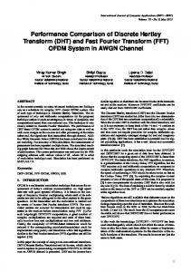
Figure 4 Architecture of I/FFT 1024 Point Radix 4
Figure 4 explains the data processing at each stage of 1024 point FFT. There are 5 stages of multiplication 4 point FFT butterfly. The output of each stage will be directly stored and processed for the next stage. Complex value which is the result of butterfly 1024 , calculated by determining the cosine and sine values by
34
Int. Journal of Applied IT Vol. 01 No. 02 (2017)
conventional calculation. The results of the calculation of complex values are then stored in ROM to meet the needs of each of its state.
3.2. MATLAB-based Simulation In the process of designing a processor FFT 1024 point radix-4, the first stage is done by simulating the system in MATLAB. System design process in MATLAB refers to the design of the block FFT. Fourier transformation block is split into five main stages of derivation results FFT 1024 points. Furthermore, each stage of the FFT block is processed by the method of radix-4, and randomly pulled out to fit with the frequency decimation techniques. Finally, the data output of the third stage rearranged so that the order of the data returned to normal. The results of the function FFT is designed and then compared with the results of the function of the FFT in MATLAB 2012a. The following are the results of simulation in MATLAB with 4 times the input testing techniques. Figure 5 (a) and (b) shows the simulation results of FFT in MATLAB by providing appropriate input in the Table 1. Table 1 Sample of Input Feed for In phase and Quadrature Index Number I Q
0 1 0
(a)
1 1 0
2 1 0
3 1 0
4 0 0
5 0 0
(b)
Figure 5 Value Plot of FFT 1024-Point in MATLAB for Data on Table I. (a) In-Phase Component, (b) Quadrature Component
4. Result Figure 6 shows the result of the simulation on timing using ModelSim for 1024FFT system with appropriate input. The simulation as designed before take 4 stage to finish the calculation and reorder the results as shown in Figure 7.
Figure 6 First Stage Input Simulation System FFT 1024 Point Radix-4
Int. Journal of Applied IT Vol. 01 No. 02 (2017)
Figure 7 Simulation Result FFT system 1024 points Radix-4
The first data output from the simulation results will be issued at 615.15 ns as show in Figure 7. This will be the processing delay on the FPGA if we simulate the system with 100 MHz clock as we targeted it on FPGA.
Figure 8. Dataflow Simulation of 1024-Point FFT Radix-4
Figure 8 shows the process of sending data from input to system output. So the data in the form of bits that were entered in the input will be processed in each block in accordance with their respective functions and then issued to the output. From the simulation results above, it was found that the design of FFT 1024 point system with radix-4 which has been designed has the same shape and value with modeling result in MATLAB and manual calculation on Ms. Excel. The system simulation to be implemented in this FPGA board requires a total clock cycle of 7177 clocks to run this system.
5. Conclusion Design of FFT 1024-point radix-4 Cooley-Tukey algorithm using the method of Decimation in Frequency has been designed using VHDL language and verified using MATLAB. For system simulation, ModelSim is used to verify logic timing. This research will become our background for synthesize and implement the
35
36
Int. Journal of Applied IT Vol. 01 No. 02 (2017)
system to FPGA. The FFT block also can be develop to implement the inverse Fast Fourier Transform.
Bibliography [1]
[2] [3]
[4]
[5]
[6]
[7] [8] [9] [10] [11] [12]
Denny Darlis, Achmad Ali Muayyadi, Sony Sumaryo., “Perancangan dan Implementasi Prosesor OFDM Baseband untuk Prototipe Modem PLC pada FPGA“, Jurnal Penelitian dan Pengembangan Telekomunikasi, Volume 15, No.2, Desember 2010, Institut Teknologi Telkom, ISSN No. 1410 – 7066 Manalu, Manoto J.F. 2011. Perancangan dan Implementasi Prosesor I/FFT 512 Titik Radiks-8 Pada FPGA. Research on Telkom Institute of Technology: Unpublished. Irawan, Ade. 2008. Model dan Perancangan FFT/IFFT 256 Titik Radix-4 untuk Chipset Baseband WiMAX. Jurnal thesis pada Institut Teknologi Bandung : Unpublished. Kadiran, Kamaru A. 2005. Design and Implementation of OFDM Transmitter adn Receiver on FPGA Hardware. Thesis on Universitiy Technology of Malaysia : Unpublished. Khairuddin, Labib Ahmad. 2011. Perancangan dan Implementasi Prosesor FFT 256 Titik-OFDM Baseband Berbasis Pengkodean VHDL pada FPGA. Research on Telkom Institute of Technology: Unpublished. Maesa, Siska Cucu. 2011. Perancangan dan Implementasi Sistem Multicarrier Code Division Multiple Access (MC-CDMA) Menggunakan VHDL pada FPGA. Research on Telkom Institute of Technology: Unpublished. Nilsson, Magnus. 2001. FFT Realization and Implementation on FPGA. Griffith University. Orfanidis J., Sophocles. 2010. Introduction to Signal Processing. Rutgers University. Oppenheim, Alan V., 1998. Discrete-Time Signal Processing. Massachusetts Institute Of Technology. Pedroni, Volney A. 2004. Circuit Design With VHDL. MIT Press Cambridge, Massachusetts London, England. Uwe Meyer-Bease. Digital Signal Processing with Field Programmable Gate Array. Springle-Verlag, 2001. Wada, Tomohisa. The 10th International LSI Design Contest. The University of The Ryukyus. [Online] October 2006. Available : http://www.ie.uryukyu. ac.jp/~wada/design07/spec_e.html.