MATEC Web of Conferences 245, 06008 (2018) EECE-2018
https://doi.org/10.1051/matecconf/201824506008
Simulation of the joint effect of rotor-stator interaction and circumferential temperature unevenness on losses in the turbine stage Nicolay Kortikov1,* 1 Peter
the Great St. Petersburg Polytechnic University, Polytechnicheskaya 29, St. Petersburg, 195251, Russian Federation.
Abstract. The article devotes to problems of unsteady interaction of the hot streams downstream of the combustion chamber with the rotating blades of the rotor wheel. The hot streams downstream of the combustion chamber are caused by discrete circumferentially located fuel nozzles and openings for air supply to the combustion chamber mixing zone. Unsteady interaction of the hot streams with the rotating blades of the rotor wheel leads to local redistribution of the time average gas flow temperature which has effect on the blade – “temperature segregation”.
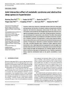
1 Introduction The basis of any gas turbine engine is a gas generator consisting of a high-pressure compressor, a combustion chamber and a high-pressure turbine (HPT). The use of a reliable gas generator in the design of a number of engines differing in thrust (dimension), minimizes the technical risk of creating an engine and significantly shortens the time and costs for certification tests. Among the important parameters is the unevenness of the gas temperature field at the exit from the combustion chamber (Fig. 1,a), which has a significant effect on the reliability of the turbine [1,2]. The hot streams downstream of the combustion chamber are caused by discrete circumferentially located fuel nozzles and openings for air supply to the combustion chamber mixing zone. Unsteady interaction of the hot streams with the rotating blades of the rotor wheel (Fig. 1,b) leads to local redistribution of the time average gas flow temperature which has effect on the blade – “temperature segregation”.
*
Corresponding author:
[email protected]
© The Authors, published by EDP Sciences. This is an open access article distributed under the terms of the Creative Commons Attribution License 4.0 (http://creativecommons.org/licenses/by/4.0/).
MATEC Web of Conferences 245, 06008 (2018) EECE-2018
https://doi.org/10.1051/matecconf/201824506008
b
a
Fig 1. The design of the engine combustion chamber with a real field temperature (a); picture of the interaction of hot jets with working blades (b)
An important concept in improving the thermal condition of turbine blades is the “clocking effect of hot spots". Adjusting the hot spot positions relative to the nozzle blades can be used to control the blade temperatures in gas turbines. It was shown [3-9] that the clocking effect when the hot spot is directed to the inlet edge of the nozzle blade reduces the effect of hot spots on the subsequent impeller. This can be explained by increased braking and increased mixing of the hot spot with the trace of the nozzle apparatus. Turbomachinery flows are among the most complex flows encountered in fluid dynamic practice. The complexity is mainly reflected, in particular, in the following areas [10]: various forms of secondary flow caused by viscosity and complex geometry, which is dominated by vortex flows: passage, leakage, corner, trailing, horseshoe and scraping vortices (these form three-dimensional and rotational nature of the flow); inherent unsteadiness due to the relative motion of rotor and stator blade rows in a multistage environment. The industrial design of turbomachinery is usually based on steady flow analysis, for which the reference simulation tool are the three-dimensional Reynolds-Averaged Navier– Stokes (RANS) steady computations. However, this approach finds its limits when unsteady phenomena become dominant. In such a context, engineers now need to account for unsteady flow effects as early as possible in the design cycle, which makes efficiency of unsteady computations a key issue [11]. A specificity of turbomachinery flows is their periodicity, at least as far as the mean field properties are considered. Modeling of non-stationary rotor-stator (transient rotor /stator - TRS) interaction is connected with calculation on the grid, taking into account the time variation of the rotor position relative to the stator (sliding mesh) [12]. In this approach, numerical simulation is carried out with reference to the full impeller or a multiple ratio of the number of blades for the stator and rotor gratings of the stage using the periodicity conditions. In the event of a violation of the multiplicity condition for the number of blades in a stage, nonstationary computations in which the periodicity condition is applicable are performed on the basis of a newly developed family of methods for calculating in blades, known as " Fourier transform." Fourier-based time methods for periodic flows have undergone major developments in the last decade as they allow to reduce the computational cost of unsteady simulations as compared to standard time-marching techniques. The basic idea is to decompose the timedependent flow variables into Fourier series, which are then injected into the equations of the problem. The time-domain problem is thus made equivalent to a frequency-domain problem, where the complex Fourier coefficients are the new unknowns. The other strategy is to cast the problem back to the time domain using the inverse Fourier transform - Harmonic Balance (HB) method [13].
2
MATEC Web of Conferences 245, 06008 (2018) EECE-2018
https://doi.org/10.1051/matecconf/201824506008
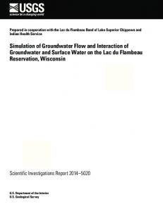
The nonlinear stator-rotor interaction together with the symmetric temperature unevenness lead to a change in the field of the time-averaged total temperature at the inlet to the rotor (relatively uniform temperature distribution at the entrance to the stage) [14,15]. The aim of this paper is to study the deflection of the position of a hot spot simulating the position of a burner jet from the axis of symmetry at the entrance to the stage to the development of secondary currents and, consequently, the magnitude of the losses in the stage. To solve the problem posed, three variants of the arrangement of the burner jet in the inlet section were considered: the first variant (Fig. 2,a) corresponded to the central location of the circular inhomogeneity of the gas flow temperature (CP), the second case (Fig. 2,b) - the hot gas spot was displaced to the pressure side of the nozzle vane (PS); third case (SS) is the displacement to the suction side (Fig. 2,c).
a
b
c
Fig 2. Different positions of the "hot spot" in the input plane of the computational domain: CP- position (a); PS- position (b); SS - position (c)
2 Numerical aspects of the model Calculation of gas-dynamic processes in the turbine stage [12] was carried out on the basis of Navier - Stokes equations and energy averaged over Reynolds using the package STAR CCM+ [16]. They are written in an integral form for a moving control volume in a relative coordinate system rotating at the angular velocity of the rotor. The time step is taken to be 5∙10-6s. The mass flow rate at the input and output boundaries was used to control the convergence of the problem. The calculation method is implicit and the Spalart–Allmaras model is used as a turbulence model. As a working medium, air is selected, the thermophysical properties of which were calculated by the model of a perfect gas. The total pressure at the inlet corresponded to the degree of pressure drop in the stage, 6 equal to 1.4. Reynolds number (Re) for the stator part - Re 1.05 10 , the rotor part 1 5 Re 2.28 10 . Rotor speed is equal to 5000rpm. 2 The number of blades in the rows are equal for the stator Z =24 and for the rotor Z s R =48. Mesh is equal 1.3 million Hex cells (Fig 3).
3
MATEC Web of Conferences 245, 06008 (2018) EECE-2018
https://doi.org/10.1051/matecconf/201824506008
a
b
Fig 3. Calculational grid with Y+ = 1.0 – 16; CFL number = 5.0: the axial section (a). the meridional section (b)
The total temperature at the entrance to the stage is given in the form of dependence:
T 420 K , if r 0.01 ; T 350 K , if r 0,015
(1)
3 2 T 1.12 E 9 r 4.2 E 7 r 5.04 E 5r 1.54 E 3 , if 0.01 r 0.015
(2)
The radial coordinate r (in meters) of the cylindrical coordinate system is measured from the pole located in the inlet section of the computational domain. In this case the parameter of unevenness - T /T 1.173 . The fundamental frequency of the flow excitation max aver. in the nozzle array due to the rotation of the working grating is 5000 rpm f Z R 4.0kHz , while in the working grid - 2.0 kHz . s 60 2.1 The structure of the flow in the output section of the turbine stage The total pressure fields in the output section of the turbine stage (Fig.4) show that at the same rotor position for the third case (Fig. 4,c), an increase in the dimensions of the inhomogeneity zones is observed, which can be identified as vortex structures with a simultaneous decrease in the maximum value of the total pressure on the scale of values.
a
b
c
Fig. 4. Total pressure fields for three cases: CP - (a); PS - (b); SS - (c)
The analysis of the total temperature fields for three cases (Fig. 5) notes that a shift in the temperature unevenness to the convex side of the nozzle blade leads to complete adherence of the various vortex structures to one with a shape close to the "heart-shaped" one (Fig. 5,c).
4
MATEC Web of Conferences 245, 06008 (2018) EECE-2018
https://doi.org/10.1051/matecconf/201824506008
This indicates a possible increase in the helicity integral, which is responsible for the topology of the vortex structures in the flow field.
a
b
c
Fig. 5. Fields of total temperature for three cases: CP - (a); PS - (b); SS - (c)
3 Comparative analysis of losses in the turbine stage The paper assumes that the dynamics of large-scale eddies in flowing parts of turbomachines is associated with such a notion as helicity [17, 18]. The term helicity refers to the integral over the volume (surface or line) 𝐻 = ∫𝐹 𝝎 ∙ 𝒖 𝑑𝐹 from the scalar product of the velocity vector 𝒖 to its vorticity 𝝎. In [19] the integral is called the helicity of the velocity field or the helicity integral. Helicity closely intertwines with the mathematical theory of nodes and in principle reflects the topology of the system, that is, the relative position of several vortices or parts of the vortex relative to others [19,20]. The sign of helicity shows the direction of rotation of the vortex with respect to the direction of flow (clockwise or counter clockwise). Expression for the calculation of isentropic efficiency changes is due to the formation of large-scale vortex structures in the inter-blade channel of the turbomachine is equal to:
is
H
(3)
* c T T p 0 2 is
In formula (3), the lower indices “0” and “2” correspond to the parameters of the flow at the inlet and outlet of the stage,
cp - heat capacity at constant pressure: T * - inlet total 0
temperature; T - outlet isentropic temperature. 2 is The results of calculations (Table 1) with the help of formula (3) indicate a decrease in the efficiency of the stage by 1.26% when the combustion zone hits the convex side of the nozzle vane, which is apparently connected with the activation of secondary currents occurring in the turbine stage. The shift of the hot spot in the direction of the concave surface of the vane practically does not affect the efficiency of the stage due to the small changes in the fields of total pressure and temperature (Fig. 4 and 5). Table 1. Results of comparative analysis of the loss in the turbine stage
Difference is %
Rotor PS-CP +0.013
STAR CCM+ and formula (3)
4 Conclusions 5
SS-CP -1.26
MATEC Web of Conferences 245, 06008 (2018) EECE-2018
https://doi.org/10.1051/matecconf/201824506008
The necessity of three-dimensional non-stationary formulation for the creation of a mathematical model for the gas generator of an aircraft engine is shown, which, in particular, affects the analysis of the conditions for supplying the combustion zone (in the circumferential direction) to the input of the turbine stage. This causes the possibility of the existence of optimal relationships between the number of nozzles and the numbers of vanes and working blades. This conclusion is in agreement with the general trend to introduce three-dimensional approaches in the design of powerful steam turbine diffusers [21]. The author thanks N. Kuznetsov and A. Yakunin for a detailed discussion of the results of the article and valuable remarks.
References 1 A. Inozemtsev., V. Sandratsky. Gas turbine engines. OAO Aviadvigatel. Permian. 1204p. (2006). 2 A. Grigoriev, V. Mitrofanov, O. Rudakov, N. Salivon. Theory of the combustion chamber. 227p. (2010). 3 B. Khanal, L. He, J. Northall and P. Adami. Unsteady aerothermal behavior of HP turbine stage under influence of combustor hot streak and swirl. Proceedings of ISUAAAT. (2013). 4 T. Shang, G. Guenette, A. Epstein and A. Saxer. The influence of inlet temperature distortion on rotor heat transfer in transonic turbine. AlAA Paper 95-3042. (1995). 5 S. Harasgama. Combustor Exit Temperature distortion effects on Heat Transfer and Aerodynamics within a Rotating Turbine Blade Passage. ASME Paper 90-GT-174. (1990). 6 R. Moss, M. Oldfield. Measurements of Hot Combustor Turbulence Spectra. ASME paper 91- GT-351. (1991). 7 D. Dorney, R. Davis, D. Edwards, N. Madavan. Unsteady Analysis of Hot Streak Migration in a Turbine Stage. AIAA Paper 90-2354. (1990). 8 P. Gaetani, G. Persico. Hot streak evolution in an axial HP turbine stage. Proceedings of 12th European Conference on Turbomachinery Fluid dynamics & Thermodynamics (ETC12) ETC 2017-182. Stockholm. Sweden. 14 p. (2017). 9 I. Qureshi, A. Smith, T. Povey. HP vane aerodynamics and heat transfer in the presence of aggressive inlet swirl. GT2011-46037. Proceedings of ASME Turbo Expo. Vancouver, British Columbia. Canada. (2011). 10 B. Lakshminarayana. J. Fluids Engineering, 113(3), (1991). 11 Numerical simulation of unsteady phenomena in gas turbine engines. Edited by V. Avgustinovich and Y. Shmotin. M.: Publishing house mechanical engineering. 536 p. (2005). 12 A.V. Grigoriev, A.I. Yakunin, N.B. Kuznechov, V.F. Kondratiev, N.N. Kortikov, St. Petersburg State Polytechnic University Journal of Engineering Science and Technology, 1(166), 183-191 (2013). 13 A. Grigoriev, A. Iakunin, N. Kuznechov, V. Kondratiev, N. Kortikov. 10-th European conference on turbomachinery. Fluid Dynamics and Thermodynamics. Conference proceedings, Lapperanta. University of Technology. Finland, 854-864. (2013). 14 A. Iakunin. Star-global-conference - 2014. March 17-19. Vienna. (2014).
6
MATEC Web of Conferences 245, 06008 (2018) EECE-2018
https://doi.org/10.1051/matecconf/201824506008
15 N. Kuznetsov, N. Kortikov, XII International Scientific and Practical Conference “Solution of Heat and Mass Transfer and Strength Problems” (2017).
16 User Guide STAR-CCM+ 10.06. CD-adapco. 10998p. (2015). 17 F. Saffman. Dynamics of vortices. 376p. (2001). 18 S. Alekseenko, P. Kuibin, V. Okulov. Introduction to the theory of concentrated vortices. Novosibirsk: Institute of Thermophysics. SB RAS. 504p. (2003). 19 M. Kurgansky, Izv. RAS. Physics of the atmosphere and ocean, 53 (2), (2017). 20 O. Mitrofanova. Hydrodynamics and heat transfer of swirling flows in the channels of nuclear power plants. 288p. (2010). 21 A. Kirillov, S. Galaev, V. Isupov, E. Smirnov, St. Petersburg State Polytechnic University Journal of Engineering Science and Technology, 4 (207), 16-25 (2014).
7