Simulation of Three Dimensional Elevator System Using Cell-DEVS Formalism Mohammad Moallemi, Ali Arya, Gabriel Wainer Dept. of Systems and Computer Engineering, Carleton University, Ottawa, Canada. {moallemi, gwainer}@sce.carleton.ca,
[email protected]
Keywords: Cellular Automata, Cell-DEVS, Three Dimensional Elevator System. Abstract Complex physical systems have been studied for many years using different approaches. Skyscraper building heights are restricted by the design limitations of their elevator systems. Long cable elevator systems will cause stretch because of their own weight. A newer technology is electromagnetic elevators that are able to travel in three dimensions and have no limitation on their height. M&S (Modeling and Simulation) methodologies and tools provide means for cost-effective validity analysis for designing complex physical and mechanical systems. Cell-DEVS is a formal methodology for cell-divided models based on DEVS (Discrete Event System Specifications) formalism. In this work, a cellular simulation model is used to model a three dimensional elevator system in a tall building with huge occupied area. The model defines appropriate rules for cells to control the elevators moving in different directions, while applying certain regulations to their movement to avoid collisions. Path finding and collision avoidance strategies are used to simulate an applicable system. We present the elevator model specifications, simulation design and discuss different simulation scenarios. 1.
INTRODUCTION AND MOTIVATION Complex physical systems have been studied for many years using different approaches. In most cases, partial differential equations have been used to solve these kinds of problems. Analytical solutions for these problems are not practical in real life. Nevertheless, the appearance of computers allowed solving the problem from different point of view. Even in these days, differential equations are implemented in digital computers to solve physical and mechanical problems. Unfortunately, the complexity of certain problems is such that no solution can be found. In these cases, the use of computer simulation allowed viewing more complex problems in a different way, providing solutions to specific problems. Defining model for the system under study provides a framework for formal representation of the system and enables us to program the model using computer. Modeling and Simulation (M&S) methodologies and tools have provided means for cost-
effective representation and validity analysis of different physical systems. M&S-based testing is a popular technique, which is widely used for these systems, since the lack of practical analytical solution encourages simulationbased solution. Among existing M&S techniques, cellular automata is a popular cell-based simulation approach, which is a discrete model, composed of a network of cells in which; each cell has a finite number of states [1]. Time is also discrete. The state of each of the cells in time t is a function of states of its predefined neighbor cells in time t-1. Cellular automata can be used in cellular simulation of physical systems in which each cell represents an entity, and events are represented as sequences of state changes of the cells. Cell-DEVS theory introduced a novel mechanism for computation, based on asynchronous cellular models with explicit timing constructions [2], [3]. The technique has been used to develop a wide variety of models in different fields, ranging from environmental sciences, traffic, biology and physical systems. Cell-DEVS is based on DEVS which provides a framework for construction of hierarchical models in a modular fashion, and makes it ideal for describing naturally hierarchical systems [4]. Likewise, its discrete-event nature improves the execution performance of the models, due to the asynchronous nature of the events occurring in the cell. Cell-DEVS cellular simulation technique has been used in this work to simulate complex three dimensional elevator systems for tall buildings. We use cellular technique to represent the building structure, elevator tunnels and elevator cars. Appropriate rules are defined to control the movement of the elevators in the tunnels, while making it possible to have higher number of elevators compared to the number of tunnels available. Simulation provides a visual representation of the system, taking into account different collision avoidance and path finding solutions. The result of the simulation helps engineers to study the system in a simulated model, with less cost and time resources. 2.
BACKGROUND Cell-DEVS methodology has extended the DEVS formalism, allowing the implementation of cellular models with timing delays. A Cell-DEVS model is a lattice of cells
holding state variables and a computing apparatus, which is in charge of updating the cell state according to a local rule. This is done using the present cell state and those of a finite set of nearby cells (called its neighborhood). Cell-DEVS improves execution performance of cellular models by using a discrete-event approach. It also enhances the cell’s timing definition by making it more expressive. Each cell is defined as a DEVS atomic model, and it can be later integrated to a coupled model representing the cell space. Cell-DEVS atomic models are informally defined as shown in Figure 1.
Figure 1- Description of a Cell-DEVS atomic model Each cell uses N inputs to compute its next state. These inputs, which are received through the model's interface, activate a local computing function (τ). A delay (d) can be associated with each cell. The state (s) changes can be transmitted to other models, but only after the consumption of this delay. Once the cell behavior is defined, a coupled Cell-DEVS can be created by putting together a number of cells interconnected by a neighborhood relationship. A CellDEVS coupled model is informally presented as shown in Figure 2.
Figure 2- Description of a Cell-DEVS coupled model Cell-DEVS coupled models represent the cell space as follows: GCC = < Xlist, Ylist, I, X, Y, n, {t1,...,tn}, N, C, B, Z, select > where Xlist: is the input coupling list; Ylist: is the output coupling list; I : represents the definition of the model’s interface; X: is the set of external input events; Y: is the set of external output events; n: is the dimension of the cell space;
{t1,...,tn}: is the number of cells in each dimension; N: is the neighborhood set; C : is the cell space; B : is the set of border cells; Z: is the translation function; and select: is the tie-breaking function for simultaneous events. A coupled model is composed of an array of atomic cells (C) with given size and dimensions where each cell is connected through standard DEVS input/output ports to the cells defined in the neighborhood (N). Since the cell space is finite, the borders of the cells are either connected to a different neighborhood than the rest of the space, or they are “wrapped” (i.e. B = {∅}) in which they are connected to those in the opposite one using the inverse neighborhood relationship. However, border cells have a different behavior due to their particular locations, which result in a non-uniform neighborhood. The Z function defines the internal and external coupling of cells in the model. It translates the outputs of the ith output port in cell Ca into values for the ith input port in cell Cb. Select function has similar functionality as in basic DEVS models, which is the tie-breaking function for the imminent components. CD++ [5],[6] is an M&S tool that was defined using the DEVS and Cell-DEVS specifications. The toolkit includes facilities to build DEVS and Cell-DEVS models. CD++ is built as a class hierarchy of models related with simulation processing entities. DEVS Atomic models can be programmed and incorporated onto a class hierarchy programmed in C++. Coupled models can be defined using a built-in specification language. Cell-DEVS models are built following the formal specifications for DEVS models (informally presented in this section), and a built-in language is provided to describe them. CD++ makes use of the independence between modeling and simulation provided by DEVS, and different simulation engines have been defined for the platform. Once an atomic model is defined, it can be combined with others into a multicomponent model using a specification language specially defined with this purpose. CD++ also includes an interpreter for Cell-DEVS models. The language is based on the formal specifications of Cell-DEVS. The model specification includes the definition of the size and dimension of the cell space, the shape of the neighborhood and borders. The cell’s local computing function is defined using a set of rules with the form POSTCONDITION DELAY {PRECONDITION}. These indicate that when the PRECONDITION is satisfied, the state of the cell will change to the designated POSTCONDITION, whose computed value will be transmitted to other components after consuming the DELAY. If the precondition is false, the next rule in the list is evaluated until a rule is satisfied or there are no more rules.
3.
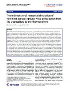
PROBLEM DEFINITION Currently, building heights are restricted by the design limitations of their elevators. Elevator cables can reach a maximum length of 500 yards before they stretch too much under their own weight. A solution to this problem has been suggested for the Millennium Tower, a massive, half-mile high skyscraper. The solution [7] involves an electromagnetic elevator that operates not only in the traditional vertical dimension, but also in a horizontal dimension. This would be implemented by using horizontal transfer shafts that allow the elevator cars to move from side to side, allowing multiple cars to be stacked in a single shaft to allow for more efficient traffic routing. Figure 3 shows an example model in which a 100-floor high skyscraper with 30 blocks in length and 30 blocks in width is shown. Four vertical elevator tunnels are located at each corner of the building and three horizontal tunnels connect the four vertical ones, one in the first floor, one in the 50th floor and one in 100th floor. To simplify the elevator car movements in these tunnels, they must move in regulated pathways. Two vertical tunnels are only accepting upward moving cars and two others downward moving cars. Elevator cars are only allowed to move in the right direction (as mentioned in the figure) in horizontal tunnels. 20 20
100
30
30
Figure 3- A 3D view of the elevator system in a 100-floor skyscraper The two vertical tunnels on each side of the building have 20 blocks distance from each other. On each
intersection, the elevator cars are forced to obey the traditional traffic rule (the elevator on the right must go first and the left one must yield). The three dimensional elevator system permits efficient use of tunnels, by having more elevator cars than number of vertical tunnels. The other advantage of this approach is access to both corners of a huge building. People can get in and get off at both corners of the building and travel horizontally besides vertically. The other advantage of horizontal tunnel is in emergency situations when elevators can be programmed to move to the horizontal tunnels (which are safer places) and evacuate people. 4.
PROPOSED MODEL To model the above mentioned example using CellDEVS formalism, different sketches can be found. A simple trivial model can have 30 planes of 30 by 100 cells to represent the actual size of the building, including tunnels and elevators. However, this approach consumes huge amount of memory on any system as the size of the cell space contains 90000 cells. Most of the cells that represent the walls are actually useless during the simulation. An efficient way of abstractly implementing the design is to only simulate the four planes that contain the tunnels on each side of the building. Hence, we unfold the sides of the building and make it a two dimensional cell space with four tunnels with wrapped neighbors on both sides. The four sides that contain the tunnels are unfolded and connected to each other, making a two dimensional cell space of 80 by 100 cells with four vertical tunnels and three horizontal tunnels. The number of cells drops to 8000. Figure 4 illustrates the final cell space after unfolding. The three horizontal tunnels are connected to each other from both sides. The movement direction is signed on each tunnel. This simplified design saves memory space and eliminates unnecessary computation. In Cell-DEVS the origin of the cell space is the top left cell of the plane (0,0) and as we go down the first component (y) increases and as we move laterally to the right the second component (x) increases. There are 12 intersection cells with the following coordinates: (0,0), (0,20), (0,40), (0,60), (50,0), (50,20), (50,40), (50,60), (99,0), (99,20), (99,40) and (99,60) which are shown in the figure.
1) Upward intersection rules manage movement of the elevators at the intersection between upward tunnels and lateral tunnels. These rules manage collision avoidance and also decide the next direction of an elevator car in order to get closer to the destination. 2) Downward intersection rules are applied to the intersection cell between downward moving tunnels and horizontal tunnels. They perform the same tasks as the upward intersection rules do. 3) Next destination calculation rules are used when an elevator has reached its destination. These rules decide a random location in the building as the next destination for that elevator. 4) Direct movement rules manage the horizontal and vertical movements of the elevators in the tunnels. To implement the above rules, each cell must be able to watch its above, bellow, left, right, bottom right and bottom left corners. Therefore, we used Moore neighborhood definition. Figure 6 illustrates the neighborhood definition for elevator model. Figure 4- unfolded view of the cell space Intersection cells must take care of collisions and organize the traffic based on the previously mentioned order to avoid possible collisions between elevator cars. Figure 3 illustrates a collision scenario in an intersection of a downward tunnel and a horizontal tunnel, where a downward going elevator is going to enter the intersection simultaneously with a right going cell from the horizontal tunnel. In this scenario the right moving elevator goes first because it is on the right side of the downward going elevator.
Figure 5- A collision scenario in an intersection cell In our model, each elevator starts from a random coordinate and travels towards a random destination in the tunnels. As soon as it arrives at the destination cell, it chooses another random destination and moves towards the new destination. Elevators follow the closest path to get to destinations. To organize the behaviors that govern the conceptual model, several rules must be defined to apply to each active cell in the simulation space. The rules must be consistent and cover all the cells that participate in the simulation. The rules are categorized in four groups: upward intersection rules, downward intersection rules, next destination calculation rules and direct movement rules.
Figure 6- Moore neighbourhood for elevator model Formal specification of a Cell-DEVS model for the the proposed elevator model is given by: M= Where: I= , with PX={∅ }, Py={∅}; X=Y= {0, 20, 51, 52, 53, 61, 62, 63, …}; Xlist=∅ Ylist=∅ n=9 N={(-1,-1)(-1,0),(-1,1),(0,-1),(0,0),(0,1),(1,-1),(1,0),(1,1)} {n1, n2 }= {100,80} C={Cij / i∈[1,100], j∈[1,80]} B= {∅} wrapped; Z: Pij Y1 → Pi,j-1 X1 Pi,j+1 Y1 → Pij X1 Y X Pij 2 → Pi+1,j 2 Pi-1,j Y2 → Pij X2 Pij Y3 → Pi,j+1 X3 Pi,j-1 Y3 → Pij X3 Pij Y4 → Pi-1,j X4 Pij Y5 → Pij X5
Pi+1,j Y4 → Pij X4 Pij Y5 → Pij X5
select ={(-1,-1), (-1,0), (-1,1), (0,-1), (0,0), (0,1), (1,-1), (1,0), (1,1)} A mapping between numerical cell values and different physical representations has been defined as follows: 0: represents a wall cell.
20: represents an empty (tunnel) cell. 51, 61, 71, …: represent upward going elevator cell. 52, 62, 72, …: represent downward going elevator cell. 53, 63, 73, …: represent right going elevator cell. An example elevator cell with value 51 is an upward elevator cell, as soon as it changes direction to right, its value changes to 53, and if it moves down its value become 52. The most significant digit is the id of the elevator and the least significant digit indicates its direction. Digits after decimal point are used to store elevator destination. The first two digits indicate the X component and the other two indicate Y component. For example an elevator cell with value 72.2440, is going downward, towards destination located at (24, 40) in the cell space. 4.1. CD++ Implementation As discussed earlier CD++ is an M&S tool which implements DEVS and Cell-DEVS formalisms. We used CD++ to implement three-dimensional elevator model. CD++ provides an eclipse based GUI to define Cell-DEVS atomic and coupled model and corresponding rules to govern cell state changes. We declare the four categories of rules that have been mentioned earlier. Figure 7 shows the upward moving intersection rules category, implemented in CD++ GUI. The first rule checks whether an upward moving elevator cell is going to enter the intersection, and its destination is bellow the current
row, therefore it enters the intersection but its direction changes to moving right, in order to direct it to the lateral tunnel. The second rule applies to an upward intersection cell where an upward moving cell is entering but its destination is above the current row and it is either in the same upward tunnel or in the next (downward moving) tunnel. Therefore, the elevator enters the intersection and continues upward. If the destination is in the next column, it is directed downward in the next intersection. If the destination has a lateral distance of 40 cells or more and its above the current location, the elevator is guided to the lateral tunnel, to be redirected in the next upward intersection (shown in the third rule). Rule five and six forward all the incoming traffic to the right direction because they apply to the top intersection cells. The other three rules apply to right moving elevator cells entering an upward elevator cell. Similar path finding strategy with the upward moving elevators is used for right moving elevators. The rules applying to elevators with precedence in an intersection are placed prior the rules associated with the lower priority elevator, (in this case, upward moving cells are handled prior to right moving cells as the former has precedence over the latter in an upward intersection) since the first rule that applies to an intersection will be executed. Hence the higher priority cell will first enter the intersection.
Figure 7- Upward moving rules in CD++ Similar rules have been defined for downward intersection cells. In CD++ each cell has a value at each step which gets propagated to other cells in its neighbourhood at each step. As soon as an elevator cell reaches the cell before its destination, the destination cell is informed of this achievement and a destination calculation rule applies to
that cell and replaces its destination by another random destination. Figure 8 shows the next destination calculation rules in CD++ GUI. Three rules are provided for three directions which modify the fractional part of the cell value representing the destination.
Figure 8- Next destination calculation rules Two groups of rules have been defined for direct movement inside the tunnels each of them deal with the three direction movements. First group applies to the elevator cells at each step, when they find an empty cell for the next move, they become empty cells. The second group applies to the empty cells which are going to become
elevator cells in the next step, they receive the elevator value and own this value. For each movement direction (upward, downward, right) a separate rule is defined in each group. Figure 9 shows direct movement rules in CD++ GUI.
Figure 9- Direct movement rules 4.2. Simulation Results To run the model on CD++, a value file has been provided which initializes the cell values. We construct the proposed structure presented in Figure 4, by setting the wall, tunnel and elevator cell values. The model is designed generically allowing any number of elevator cars to be introduced to the model. CD++ modeller [8] is a toolkit accompanied by CD++ which provides two dimensional representation of the cell space, by tracing the logfile of the simulation. It is capable of associating different colors to different cell values. Figure 10 represents a snapshot of the graphical representation made by CD++ Modeller toolkit. The dark gray cells represent walls, white cells represent tunnels and color cells located in the tunnels are elevator cells. The red square specifies a downward intersection where two elevators are trying to enter (discussed in Figure 11).
Figure 10- Snapshot of CD++ graphical representation of 3D elevator model
Figure 11 shows a collision scenario in a downward intersection, where two elevator cells, one from above (green cell) and one from left (brown cell) are trying to enter the intersection. The corresponding logfile of CD++ is shown under each step (zero values indicating wall cells are not printed in the logfile). Based on the traffic rules discussed before, the right going cell has precedence over the other one. The value of the left cell is 113 and its destination is (99, 70) (indicated by the digits after decimal point). The intersection cell routs the cell towards the target which in this case is routed to the lateral tunnel. Therefore the cell value does not change and it continues its path. The downward moving cell’s value is 62 and its destination is (35, 40). It enters the intersection after the left cell, and because its destination is on the right of the intersection it is routed to the lateral tunnel. Hence its value changes to 63, indicating right direction movement.
Step 1
Step 3
Step 2
Step 4
Figure 11- Collision detection scenario in CD++ modeller Figure 12 shows two pieces of the logfile in which the elevator cell with value 121 and destination (68, 0) is moving upward in the first column (Y=0, the first tunnel on the left). The numbers on the left show the row labels. As soon as the elevator cell reaches row 68 which is its destination, it randomly picks another destination and heads toward this new destination.
Figure 12- Destination achievement scenario Varieties of simulation scenarios have been tested with different number of elevator cells in different initial locations. The model was able to run the simulation correctly and rout the cells to their destinations. Two videos of the simulation results with 10 and 20 elevators are available in [9] and [10]. 5.
CONCLUSIONS Massive skyscrapers need more advanced elevator systems because of restrictions of the traditional cable elevator systems. The new elevator systems operate using electromagnetic technology and are able to travel in three dimensions. A cellular simulation model based on this technology using Cell-DEVS methodology has been presented in this paper, to verify the performance and efficiency of this system. Collision avoidance and path finding strategies have been used to safely route elevators in the tunnels. Cell-DEVS formal specifications of the model have been presented followed by the details of implementation in CD++ simulation software. The simulation proved the effectiveness and efficiency of the three dimensional elevator system as it accommodates higher number of elevators in the tunnels and provides lateral movement as well as vertical movement. These systems can be used with intelligent path finding algorithms, reducing transfer time in huge buildings.
Reference [1] Wolfram, S. "Theory and applications of cellular automata". Vol. 1. Advances Series on Complex Systems. World Scientific. Singapore. 1986. [2] The Use of Cellular Automata in the Classroom, Lilly, H.A.; Supercomputing, 1995. Proceedings of the IEEE/ACM SC95 Conference. [3] Wainer, G.; Giambiasi, N. "Timed Cell-DEVS: modeling and simulation of cell spaces ". In "Discrete Event Modeling & Simulation: Enabling Future Technologies", Springer-Verlag. 2001. [4] ZEIGLER, B.; KIM, T.; PRAEHOFER, H. "Theory of Modeling and Simulation". Academic Press. 2000. [5] WAINER G., “CD++: a toolkit to define discrete-event models”. Software, Practice and Experience. Vol. 32, No.3. pp. 1261-1306. November 2002.
[6] Wainer, G. et al. "CD++ A tool for DEVS and CellDEVS Modeling and Simulation. User's Guide". Draft. August 2004. [7] Mark Hayden, Chris Stasiuk, Tim Tober “2 Dimensional Elevator Controller” project website, available at: http://www.ee.ualberta.ca/~elliott/ee552/projects/1998_ w/elevator_controller/. [8] Chiril Chidisiuc, Gabriel A. Wainer "CD++Modeler: a graphical viewer for DEVS models" Poster, Poster Papers Workshop. SpringSim 2008. Ottawa, ON. – 2008. [9] Simulation results video with 10 elevators available at: http://www.youtube.com/watch?v=32eGuPtWotI. [10] Simulation results video with 20 elevators available at: http://www.youtube.com/watch?v=d0Tb0Am5UrY.