School of Aerospace Engineering,. Georgia Institute of Technology, ... Multibody dynamics simulation codes are used in many areas, such as the automotive, rail ...
Simulation of Wheels in Nonlinear, Flexible Multi-Body Systems∗ Olivier A. Bauchau and Jesus Rodriguez. School of Aerospace Engineering, Georgia Institute of Technology, Atlanta, GA, USA.
Abstract This paper is concerned with the modeling of wheels within the framework of finite element based dynamic analysis of nonlinear, flexible multi-body systems. The overall approach to the modeling of wheels is broken into four distinct parts: a purely kinematic part describing the configuration of the wheel and contacting plane, a unilateral contact condition giving rise to a contact force, the friction forces associated with rolling and/or sliding, and a model of the deformations in the wheel tire. The formulation of these various aspects of the problem involves a combination of holonomic and non-holonomic constraints enforced via the Lagrange multiplier technique. This work is developed within the framework of energy preserving and decaying time integration schemes that provide unconditional stability for nonlinear, flexible multibody systems involving wheels. Strategies for dealing with the transitions from rolling to sliding and vice-versa are discussed and are found to be more efficient than the use of a continuous friction law. Numerical examples are presented that demonstrate the efficiency and accuracy of the proposed approach.
1
Introduction
Multibody dynamics simulation codes are used in many areas, such as the automotive, railroad, and aerospace industries. This work deals with the modeling of wheels within the framework of nonlinear, flexible multibody systems, i.e. a collection of bodies in arbitrary motion with respect to each other while each body undergoes large displacements and rotations with respect to a body attached frame of reference. The focus is on problems where the strains within each elastic body remain small. The elastic bodies are modeled using the finite element method. For beam elements, the location of each node is represented by its Cartesian coordinates in an inertial frame, and the rotation of the cross-section at each node is represented by a finite rotation tensor expressed in the same inertial frame. The kinematic constraints among the various bodies are enforced ∗
Multibody System Dynamics, 7, pp 407 – 438, 2002.
1
via the Lagrange multiplier technique. Although this approach does not involve a minimum set of coordinates, it allows a modular development of finite elements for the enforcement of the kinematic constraints. Wheels are at the heart of numerous multibody systems and, hence, must be properly modeled within the framework chosen for the simulation. Numerous studies have focused on the rolling contact problem, such as that found in railroad applications [1]. Other researchers have concentrated on tire models directed towards applications to the automotive industry [2]. Finally, shimmy theories were developed for aerospace applications [3, 4, 5]. Few authors have addressed the modeling of wheel in a generic manner within the framework of general multibody dynamics simulation tools [6]. The present work develops a comprehensive model of wheels that can be applied to a wide range of practical problems. The overall approach to the model is broken into four distinct parts: 1) a purely kinematic part describing the configuration of the wheel and contacting plane, 2) a unilateral contact condition giving rise to a normal contact force, 3) a model of the friction forces associated with rolling and/or sliding, and 4) a model of the deformations in the wheel tire. The formulation of these various aspects of the problem involves a combination of holonomic and non-holonomic constraints that are enforced via the Lagrange multiplier technique. The first, purely kinematic part of the problem is developed in section 3. The candidate contact points [7], i.e. the points on the wheel and plane that are the most likely to come in contact, are obtained from simple geometric considerations and the definition of the relative distance q between the wheel and contacting plane follows. The second part of the model, described in section 4, is the unilateral contact condition which is readily expressed in terms of the relative distance as q ≥ 0. This contact condition can be represented as a purely kinematic condition q − r2 = 0, where r is a slack variable used to enforce the positiveness of q. In order to accommodate for the local deformation of the wheel tire, the local penetration or approach, denoted a, is defined, and the contact condition then writes q + a − r2 = 0. The third part of the model deals with the modeling of the friction forces acting between the wheel and plane at the contact point, when the wheel is either rolling or sliding on the plane. Friction is a phenomenon involving complex interaction mechanisms between the surfaces of solids being pressed into contact [8, 9]. Coulomb’s friction law has been extensively used to model friction forces. It postulates that the friction force between to bodies sliding with respect to each other is equal to the normal contact force times an empirical coefficient µk , the coefficient of kinetic friction. The friction force always acts in a direction opposing relative motion. Sliding gives way to rolling or sticking when the relative velocity vanishes. In that case, the friction force must be smaller than the normal contact force times an empirical coefficient µs , the coefficient of static friction. The formulation of the rolling condition and the evaluation of the friction forces are discussed in sections 5 and 6, respectively. Computational strategies for dealing with the transitions from sliding to rolling and vice-versa are discussed in detail and contrasted with the use of continuous friction laws. The last part of the model, developed in section 7, takes into account the elastic and damping characteristics of the wheel tire. The radial deformation a of the tire under the normal contact force is a function of the tire elasticity. However, lateral and yaw deforma2
tions of the tire must also be taken into account to order to capture the shimmy phenomenon, a self-induced instability. The formulation developed by Moreland [3], and later by Collins and Black [5] is used here. Although more complex tire models are available in the literature [4], the simple Moreland formulation seems to give good correlation with experimental measurements [5]. The discretization of the various components of this model was formulated within the framework of the energy preserving [10, 11, 12, 13, 14] and decaying schemes [15, 16, 17, 18, 19, 20, 21, 22, 23]. In these schemes, unconditional stability is achieved for nonlinear elastic multibody systems by combining two features: an energy preservation or decay statement for the elastic bodies of the system, and the vanishing of the work done by the forces of constraint. The use of these unconditionally stable schemes is of particular importance in problems involving wheels, due to the presence of a number of holonomic and non-holonomic constraints, and to the rapidly varying dynamic response of the system associated with the contact and friction forces. Numerical examples that demonstrate the accuracy and efficiency of proposed model on a variety of wheel problems are presented in the last section.
2
Kinematic conventions and notations
The kinematic description of bodies in their reference and deformed configurations will make use of three orthogonal triads. First, an inertial triad is used as a global reference for the system; it is denoted SI with unit vectors i1 , i2 , and i3 . A second triad S0 , with unit vectors e01 , e02 , and e03 is attached to the body and defines its orientation in the reference configuration. Finally, a third triad S ∗ with unit vectors e1 , e2 , and e3 defines the orientation of the body in its deformed configuration. Let u0 and u be the displacement vectors from SI to S0 , and S0 to S ∗ , respectively, and R0 and R the rotation tensors from SI to S0 , and S0 to S ∗ , respectively. In this work, all vector and tensor components are measured in either SI or S ∗ . For instance, the components of vector u measured in SI , and S ∗ will be denoted u, and u∗ , respectively, and clearly u∗ = R0T RT u.
(1)
Similarly, the components of tensor R measured SI , and S ∗ will be denoted R, and R∗ , respectively. The skew-symmetric matrix formed with the components u will be denoted u e.
3
The relative distance constraint
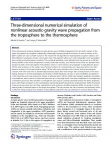
Consider a wheel of radius ρ, denoted as body `, and the contacting plane, body k, as depicted in fig. 1. In the reference configuration, the position of the wheel is defined by the position vector u`0 of its center and its orientation is determined by a body attached triad S0` , with e`30 normal to the plane of the wheel. In the deformed configuration, the wheel center undergoes a displacement u` and the orientation of the wheel is defined by a triad S ` . Contact may occur between the wheel and a plane defined in the reference configuration by the position vector uk0 of one of its points P and an orientation triad S0k , with ek3 normal to the plane. In the deformed configuration, the displacement of point P is uk and the orientation of the plane is defined by S k . 3
The candidate contact points on the plane and wheel are denoted z k and z ` , respectively, see fig. 1. The tangent to the wheel at the candidate contact point must be in the plane of the wheel and parallel to the contacting plane, i.e. normal to e`3 and ek3 , respectively. The following triad is now defined d2 =
eek3 e`3 ; h
d3 = e`3 ;
d1 = de2 d3 ;
h = |e ek3 e`3 |.
(2)
Clearly, d2 is parallel to the tangent at the candidate contact point, d1 points toward the candidate contact point, and d3 is normal to the plane of the wheel. The vector from point P to point z ` is £ ¤ £ ¤ P z ` = (u`0 + u` ) + ρ d1 − (uk0 + uk ) = u0 + u + ρ d1 , (3) where ρ is the wheel radius, u0 = u`0 − uk0 , and u = u` − uk . The distance q between the candidate contact points on the wheel and plane is found by projecting P z ` along the unit vector ek3 , as shown in fig. 1, ` kT q = ekT [u0 + u + ρ d1 ] = ekT 3 P z = e3 3 (u0 + u) − ρh,
(4)
where the last equality was obtained with the help of eqs. (2). This equation defines the relative distance q in terms of the kinematic variables of the problem; it is imposed as nonlinear holonomic constraint on the system C = q + ρh − ekT 3 (u0 + u) = 0.
(5)
As discussed in [20], holonomic constraints are enforced by the addition of a constraint potential λC, where λ is the Lagrange multiplier. The forces of constraint F c corresponding to this constraint are readily obtained as λ δC =
δuk δψ k δu` δψ ` δq
T
λ − λ − λ − λ λ
ek3 (ρ g/h) eek3 e`3 − eek3 (u0 − u) ek3 (ρ g/h) ee`3 ek3
=
δuk δψ k δu` δψ ` δq
T
F c,
(6)
k ` k kT ` `T ` are the virtual changes in orientation where g = ekT 3 e3 , and δψ = δR R , δψ = δR R for bodies k and `, respectively. The subscripts (·)i and (·)f denote the value of a quantity at the beginning and end times of a typical time step, denoted ti and tf , respectively. The change in the value of the constraint between the final and initial states is now evaluated kT Cf − Ci = (qf − qi ) + ρ (hf − hi ) − ekT (u0 + ui ) f (u0 + uf ) + ei ρ kT T T k (h2f − h2i ) − (ekT = (qf − qi ) + f − ei )(u0 + um ) − (uf − ui )em . 2hm
(7)
In view of eq. (B3), ekf − eki = rek ekm , where rk are the Rodrigues parameters used to parametrize the incremental rotation tensor for body k, see Appendix B. Furthermore, 4
(h2f − h2i )/2 = −gm (gf − gi ), and (gf − gi ) = −(r`T − rkT ) ee`m ekm . Combining all these results then yields · ¸ ρgm ` k T ` k kT k T k Cf − Ci = (qf − qi ) − (r − r ) eem em − r eem (u0 + um ) − (uf − ui ) em , (8) hm where ek3i + ek3f e`3i + e`3f ui + uf gi + gf hi + hf ; ek3m = ; e`3m = ; gm = ; hm = . (9) 2 2 2 2 2 This result suggests the following time discretization of the constraint forces sλm ek3m − sλm (ρ gm /hm ) eek3m e`3m − eek3m (u0 − um ) k , (10) F cm = − sλm e3m − sλm (ρ gm /hm ) ee`3m ek3m sλm um =
where s is a scaling factor for the unknown, mid-point value of the Lagrange multiplier λm . In view of eq. (8), the work done by the constraint forces during the time step is ∆W c = sλm (Cf − Ci ). Clearly, this work vanishes if Cf − Ci = 0. In order to avoid the drift phenomenon, it is preferable to enforce the condition Cf = 0 at each time step. Consequently, the forces of constraint are discretized in time in a manner that guarantees the satisfaction of the nonlinear constraint manifold, i.e. the constraint condition will not drift. At the same time, the discretization implies the vanishing of the work performed by the forces of constraint at the discrete solution level. Consequently, the discrete energy conservation laws proved for the flexible members of the system are not upset by the introduction of the constraints. This energy preserving formulation can be readily extended to an energy decaying formulation by following the steps outlined in section 4.3 of [20]. The discretized forces of constraint, eq. (10), can be linearized to yield the Jacobian matrix of the constraints. Within the framework of the finite element formulation, this equivalent stiffness matrix is assembled with all other stiffness contributions of the system. The Lagrange multipliers are then explicitly computed at each time step.
4
The contact condition
In the previous section, the relative distance q between the wheel and plane was computed as a function of the kinematic variables defining the body configurations. Two different types of contact problems are addressed in this section. At first, the wheel and plane are assumed to be infinitely rigid, giving rise to the inequality condition q ≥ 0. Next, localized deformations of the wheel are allowed in a small region near the contact point. In this case, the wheel center of mass is allowed to approach the plane closer than what would be allowed for a rigid wheel. This quantity is defined as the approach and denoted a; following the convention used in the literature [24], a > 0 when penetration occurs whereas q < 0 in that situation. When no penetration occurs, a = 0, by definition, and q > 0. Combining the two situations leads to the contact condition q + a ≥ 0, which implies q = −a when penetration occurs. The magnitude of the approach depends on the elastic characteristics of the wheel tire. 5
4.1
Contact condition for a rigid wheel
When both wheel and plane are rigid, the contact condition is an inequality q ≥ 0, which can be readily transformed into an equality condition q − r2 = 0 through the addition of a slack variable r. Hence, the contact condition is enforced as a nonlinear holonomic constraint C = q − r2 = 0.
(11)
Once again, this constraint is enforced via the Lagrange multiplier technique. The corresponding forces of constraint are · δC λ =
δq δr
¸T ·
λ − λ 2r
¸
· =
δq δr
¸T F c.
(12)
The change in the value of the constraint between the final and initial states is Cf − Ci = (qf − qi ) − (rf2 − ri2 ) = (qf − qi ) − (rf − ri )2rm , where rm = (rf + ri )/2. This suggests the following discretization of the constraint forces · ¸ sλm c Fm = . (13) − sλm 2rm This discretization together with the constraint Cf = 0 leads to the vanishing of the work done by the forces of constraint. The Lagrange multiplier λm is readily identified as the normal contact force. Since the slack variable is not connected to any degree of freedom of the model, the variation δr gives rise to the nonlinear equation −λm 2rm = 0 which possesses two solutions λm = 0 and rm = 0. The first solution, λm = 0, is associated with the no contact state and a vanishing contact force. The second solution, rm = 0, indicates an active contact condition and implies rf = −ri , which together with Cf = Ci = 0 results in qf = rf2 = ri2 = qi . In other words, when the contact condition is active, a contact force develops, i.e. λm 6= 0, and the relative distance between the contacting bodies remains unchanged qf = qi . For practical implementations, the introduction of the slack variable is not necessary. If at the end of the time step qf ≥ 0, the unconstrained solution is accepted and the simulation proceeds with the next time step. On the other hand, if qf < 0 at the end of the time step, the time step is repeated with the additional constraint qf = qi and the Lagrange multiplier associated with this constraint is the contact force. This strategy preserves the unconditional stability of the integration procedure.
4.2
Contact condition for an elastic wheel
When the wheel is deformable, the contact condition becomes q + a ≥ 0. Here again, this inequality condition is transformed into an equality condition C = q + a − r2 = 0 by the addition of a slack variable r. This nonlinear holonomic constraint can be dealt with in a manner identical to that developed in the above section.
6
5
The rolling constraint
When the wheel is rolling on the plane, its in-plane relative velocity components must vanish, and a friction force appears at the contact point. The inertial velocities of the candidate contact points on the wheel and plane are V ` = u˙ ` + ω e ` (ρ − a) d1 ,
(14)
V k = u˙ k + ω e k [u0 + u + (ρ − a) d1 ] ,
(15)
and respectively, where ω k and ω ` are the angular velocities of the plane and wheel, respectively. The relative velocity of the wheel with respect to the plane then becomes e k (u0 − u) + (ρ − a) (e ω` − ω e k ) d1 . V r = V ` − V k = u˙ − ω
(16)
The components of the relative velocity vector in the contacting plane are found by projecting this vector d2 Vd = V Tr d2 = u˙ T d2 − ω kT (e u0 + u e) d2 + (ρ − a) (ω ` − ω k )T e`3 ,
(17)
Vt = V Tr eek3 d2 = u˙ T eek3 d2 − ω kT (e u0 + u e) eek3 d2 + (ρ − a)(ω ` − ω k )T eek3 e`3 ,
(18)
and along eek3 d2
where the identity de1 eek3 d2 = −e ek3 e`3 was used. d2 and eek3 d2 are two mutually orthogonal, in-plane directions, called the wheel driving and transverse directions, respectively. The rolling constraints are now C1 = Vd = 0;
C2 = Vt = 0.
(19)
These nonlinear, non-holonomic constraints limit the possible variations on the kinematic variables of the problem, see [25]. Here again, these constraints are enforced via the Lagrange multiplier technique, and the corresponding forces of constraint are T δuk − λ d2 δψ k − λ [(e u0 + u e) d2 + (ρ − a) e`3 ] λ δC1 = δu` λ d2 ` λ (ρ − a) e`3 δψ
T δuk δψ k = ` F c1 , δu δψ `
(20)
in the driving direction, and T δuk − λ eek3 d2 δψ k − λ [e u0 + u e) d2 + (ρ − a) eek3 e`3 ] ek3 (e λ δC1 = k ` δu λ ee3 d2 λ (ρ − a) eek3 e`3 δψ `
in the transverse direction. 7
T δuk δψ k = ` F c2 , δu δψ `
(21)
The mid-point value of the driving direction constraint is now evaluated £ ¤ ∆t C1m = ∆t Vdm = (uf − ui )T d2m − rkT (e u0 + u e) d2m + (ρ − am ) (r` − rk )T e`3m ,
(22)
where d2m = (d2f + d2i )/2, am = (af + ai )/2, and the following expression were used for the mid-point velocities: u˙ m = (uf − ui )/∆t, ω km = rk /∆t, and ω `m = r` /∆t. This result suggests the following discretization of the constraint forces − sλm d2m − sλm [(e u0 + u em ) d2m + (ρ − am ) e`3m ] . (23) F c1m = sλm d2m sλm (ρ − am ) e`3m In view of eq. (22), the work done by the constraint forces during the time step is ∆W c = sλm C1m . Clearly, this work vanishes if C1m = 0. Consequently, the forces of constraint are discretized in time in a manner that guarantees the satisfaction of the nonlinear, nonholonomic constraint. At the same time, the discretization implies the vanishing of the work performed by the forces of constraint at the discrete solution level. Consequently, the discrete energy conservation laws proved for the flexible members of the system are not upset by the introduction of the non-holonomic constraints. Note the difference in treatment between holonomic and non-holonomic constraints: the condition of vanishing work done by the constraint forces implies Cf = Ci = 0 for the former, but Cm = 0 for the latter. The rolling constraint in the transverse direction can be treated in a similar manner. The mid-point value of the constraint is £ ¤ u0 + u e)e ek3m d2m ∆t C2m = ∆t Vtm = (uf − ui )T eek3m d2m − rkT (e +(ρ − am ) (r` − rk )T eek3m e`3m , (24) leading to the following discretization of the forces of constraint − sλm eek3m d2m − sλm [e ek3m (e u0 + u em ) d2m + (ρ − am ) eek3 e`3m ] F c2m = k sλm ee3m d2m sλm (ρ − am ) eek3m e`3m
.
(25)
This discretization together with the constraint C2m = 0 leads to the vanishing of the work done by the forces of constraint.
6 6.1
Frictional forces Coulomb’s Friction Law
To successfully treat rolling, sliding and transition states, it is necessary to properly model the frictional forces. When sliding takes place, Coulomb’s law states that the friction force F f is proportional to the magnitude of the normal contact force F n F f = −µk (Vr ) F n 8
Vr , Vr
(26)
where µk (Vr ) is the coefficient of dynamic friction and Vr is the magnitude of the relative velocity tangent to the plane, V r . If the relative velocity vanishes, rolling or sticking takes place. In this case, the frictional force is |F f | ≤ µs F n ,
(27)
where µs is the coefficient of static friction. Application of Coulomb’s law involves discrete transitions from rolling to sliding and viceversa, as dictated by the vanishing of the relative velocity and the magnitude of the friction force. These discrete transitions can cause numerical difficulties, and numerous authors have advocated the use of a continuous friction law [26, 9, 27, 28, 6, 29, 30, 31], typically written as V F f = −µk (Vr ) F n r (1 − e−|Vr |/v0 ), (28) Vr where v0 is a characteristic velocity usually chosen to be small compared to the maximum relative velocity encountered during the simulation. (1 − e−|Vr |/v0 ) is a “regularizing factor” that smoothes out the friction force discontinuity. The continuous friction law describes both sliding and rolling behavior, i.e. it replaces both eqs. (26) and (27). Rolling or sticking is replaced by “creeping” of the wheel with respect to the plane with a small relative velocity. Various forms of the regularizing factor have appeared in the literature.
6.2
Modeling frictional forces
The virtual work done by the friction forces can be written as δW f = − [δqd Fd + δqt Ft ] ,
(29)
where δqd and δqt are the virtual relative displacements in the wheel driving and transverse directions, respectively, and Fd and and Ft the corresponding components of the frictional force Fd = µk (Vr ) F n Vd /Vr ; Ft = µk (Vr ) F n Vt /Vr . (30) The virtual relative displacements in the driving and transverse direction are found in a manner similar to that described in section 5, and the virtual work done by the friction forces then becomes k T k T δu δu (Fd I + Ft eek3 ) d2 k k ` δψ u0 + u e) d2 + (ρ − a) e3 ] δψ k (Fd I + Ft ee3 ) [(e f δW f = δu` − (Fd I + Ft eek3 ) d2 = δu` F , (31) − (Fd I + Ft eek3 ) (ρ − a) e`3 δψ ` δψ ` where I is the 3 × 3 identity matrix. To ensure unconditional stability of the time integration process in the presence of friction forces, it is necessary to prove that the work done by the discretized friction forces is always dissipative. The following discretization is proposed (Fdm I + Ftm eek3m ) d2m u0 + u em ) d2m + (ρ − am ) e`3m ] (Fdm I + Ftm eek3m ) [(e , (32) F fm = k − (Fdm I + Ftm ee3m ) d2m − (Fdm I + Ftm eek3m ) (ρ − am ) e`3m 9
where Fdm = (Fdf + Fdi )/2 and Ftm = (Ftf + Fti )/2. In view of eqs. (22) and (24), the virtual work done by the frictional forces becomes ∆W f = − [Fdm Vdm + Ftm Vtm ] ∆t.
(33)
Introducing Coulomb’s friction law, eq. (26), evaluated at the mid-point then gives ∆W f = −∆t µk (Vrm ) Vrm Fmn ≤ 0.
(34)
This expression guarantees that the work done by the frictional forces is always negative, i.e. friction is always associated with energy dissipation. Consequently, the discrete energy conservation laws proved for the flexible members of the system are not upset by the introduction of frictional forces.
6.3
Computational strategy
Coulomb’s friction law states that rolling starts when the relative velocity vanishes and eq. (27) is satisfied. In practice, it is inconvenient to determine the exact instant when the relative velocity vanishes, i.e. when Vr = 0. Rather, the rolling constraints, eqs. (19), are enforced when Vr ≤ v0 , where v0 is an appropriately selected characteristic relative velocity. If v0 is chosen to be too large, a premature transition from rolling to sliding will take place, and if v0 is too small, the transition may not take place. In the examples presented in section 8, v0 was chosen to be about 1% of the maximum relative velocity encountered during the simulation. The Lagrange multipliers associated with the non-holonomic rolling constraints yield the static friction force. The rolling constraints remain active for as long as eq. (27) holds. If it is no longer satisfied, the time step is rejected and restarted using Coulomb’s friction law. As mentioned in section 6.1, numerous authors advocate the use of a continuous friction law such as that presented in eq. (28). The continuous friction law describes both sliding and rolling behavior, i.e. it replaces both eqs. (26) and (27), and can be used during the entire simulation. Here again, the characteristic relative velocity v0 appearing in eq. (28) should be carefully selected. If chosen too small, a near discontinuity is recovered in the friction law and numerical problem ensue; if too large, erroneous results will arise because the value of the friction coefficient is incorrect over a wide range of relative velocities. In the examples presented section 8, v0 was chosen to be about 1% of the maximum relative velocity encountered during the simulation. To be fully effective, both Coulomb’s friction law and the continuous friction law must be used together with an automated time step size selection procedure. As the norm of the relative velocity approaches v0 , the time step size should be chosen small enough so that changes in relative velocity in the subsequent time steps are small compared to v0 . In this work, the following strategy was used: when v0 ≤ Vr ≤ 5v0 , the new time step, ∆tnew , is selected such that the estimated change in relative velocity ∆Vr ≈ v0 /2; similarly, when Vr ≤ v0 , ∆tnew is chosen such that the estimated change in relative velocity ∆Vr ≈ v0 /3. 10
A simple linear extrapolation based on the previous time step size ∆told and corresponding relative velocity Vr old was found to predict ∆Vr with sufficient accuracy. Of course, the accurate solution of the dynamical equations of motion of the entire system also require the selection of an adequate time step size. An automated time step size selection procedure based on system total energy considerations was developed in [20] and was used in this work to obtain accurate solutions in an efficient manner. The smallest time step size required by the various adaptivity strategies was used to proceed with the simulation.
7
Tire deformation model
The elastic and damping characteristics of the wheel tire significantly alter the system dynamic response. The radial deformation a of the tire under the normal contact force is a function of the tire elasticity that is modeled when enforcing the relative distance constraint, see section 4. Furthermore, the lateral and yaw deformations of the tire must also be taken into account to order to capture the shimmy phenomenon, a self-induced instability. The formulation developed by Moreland [3], and later by Collins and Black [5] is used here. Their model is conveniently described in terms of two rigid wheels [32]. The first wheel models the actual wheel and carries its actual mass properties. The second wheel is a fictitious, massless wheel that is aligned with the tire foot-print, as depicted in fig. 2. Two variables define the configuration of the fictitious wheel: the lateral displacement ∆ of its center and the yaw angle Ψ. This wheel is assumed to remain at all times in rolling contact with the plane, and is connected to the frame that supports the actual wheel by means of linear and torsional springs and dampers. Assuming that ω `T e`3 = ω f T c3 , i.e. the angular velocities of the actual and fictitious wheels in the directions perpendicular to their respective planes are identical, the linear and angular velocities of the fictitious wheel can be written as
and
˙ e` + ∆ ω e ` e`3 , V f = u˙ ` + ∆ 3
(35)
˙ d1 − ω `T e` (1 − cos Ψ) e` − ω `T e` sin Ψ d2 , ωf = ω` + Ψ 3 3 3
(36)
respectively. The deformations of the tire give rise to the cornering force F and aligning torque M , both taken as positive quantities when acting on the wheel along the directions of ∆ and Ψ, respectively. Moreland’s theory assumes the following constitutive relationships ¸ · ¸ · ¸· ¸ · ¸· ˙ F k1 0 ∆ µ1 0 ∆ (37) = + ˙ , M 0 k2 Ψ 0 µ2 Ψ where k1 , k2 , µ1 , and µ2 are experimentally measured coefficients. The cornering force is ˙ where CΨ and c1 are two also related to the yaw angle through CΨ F = −(Ψ + c1 Ψ), additional empirical coefficients. Equating the two expressions for the cornering force yields a non-holonomic constraint ˙ = 0. ˙ + 1 Ψ + c1 Ψ (38) C = k 1 ∆ + µ1 ∆ CΨ CΨ 11
The present implementation of Moreland theory can be summarized as follows. Two additional kinematic variables, ∆ and Ψ are related by a non-holonomic constraint, eq. (38). These tire deformations give rise to the cornering force F and aligning torque M given by the tire constitutive laws, eq. (37). Finally, the rolling constraints should be applied to the fictitious wheel whose velocities are defined in eqs. (35) and (36). These three aspects of the problem are briefly discussed in the following sections.
7.1
The relative distance constraint for a deformable tire
The presence of the lateral deformation ∆ slightly alters the expression for the relative distance between the candidate contact points z ` and z k , yielding q = ekT 3 (u0 + u) − ρh + g ∆.
(39)
This expression should be compared with eq. (4) developed earlier. The discretization procedure for the constraint forces described in section 3 can be readily adapted to the present constraint, resulting in very similar expressions.
7.2
The rolling constraint for a deformable tire
For a deformable tire, the velocities of the candidate contact points on the fictitious wheel and contacting plane are Vc =Vf +ω e f (ρ − a) d1 , (40) and V k = u˙ k + ω e k [u0 + u + (ρ − a) d1 + ∆ e`3 ],
(41)
respectively. These expressions are comparable with eqs. (14) and (15) developed for the rigid tire. Introducing the velocities of the fictitious wheel, eqs. (35) and (36), then yields the relative velocity. The rolling constraints correspond to the vanishing of the relative velocity in the wheel driving and transverse directions, i.e. £ ¤ C1 = Vd = u˙ T d2 − ω kT (e u0 + u e) d2 + (ω ` − ω k )T (ρ − a) e`3 − ∆ d1 −ω `T e`3 (ρ − a) (1 − cos Ψ) = 0, (42) and £ ¤ C2 = Vt = u˙ T eek3 d2 − ω kT (e u0 + u e) eek3 d2 + (ω ` − ω k )T (ρ − a) eek3 e`3 − g ∆ d2 ˙ h − ω `T e` (ρ − a) sin Ψ h = 0, −∆ 3
(43)
respectively. The following identities were used: e`T ek3 d2 = −h and ee`3 eek3 d2 = −g d2 . These 3 e two constraints should be compared with eqs. (19), corresponding to the case of a rigid tire. The discretization procedure for the constraint forces described in section 5 can be adapted to the present situation and very similar expressions are obtained.
12
8
Numerical examples
The proposed wheel formulation will be validated with the help of different numerical involving the contact condition, rolling and/or sliding with multiple transitions, as well as a deformable tire.
8.1
Contact of a wheel-beam system
The first example deals with the wheel-beam system depicted in fig. 3. A flexible, homogeneous beam of length l is pinned at point R to a fixed support located a distance h above a moving road. The beam tip is connected to a wheel by means of a revolute joint that includes a torsional damper of damping constant C. The wheel of mass M is flexible in the radial direction, has a uniformly distributed mass and a radius ρ. The road moves at constant velocity V . Gravity acts on the system at all times. The physical properties of the system are as follows: wheel mass M = 15.0 kg and radius ρ = 0.25 m; damping constant C = 0.01 N m/sec; road velocity V = 8.0 m/sec; vertical distance h = 3.995 m; static coefficient of friction µs = 0.40, kinetic coefficient of friction µk = 0.40; acceleration of gravity g = 9.81 m/sec2 ; characteristic relative velocity v0 = 0.05 m/sec. The beam sectional properties are listed in the first set of table 1. The relationship between the normal force F n and the approach a is F n = k1 a+k2 a2 +k3 a3 +k4 a4 with the following constants k1 = 1.755 M N/m, k2 = 463.5 M N/m2 , k3 = −18.560 GN/m3 and k4 = 303.750 GN/m4 . Two cases have been considered, denoted case 1 and 2. In case 1, transitions from rolling to sliding and vice-versa are allowed, imposing the rolling constraints and Coulomb’s friction law. In case 2, the continuous friction law, eq. 28, is used at all times. Fig. 4 depicts the history of the beam root rotation, φR . In this figure and subsequent ones, the thick horizontal solid lines indicate the extent of rolling events whereas the thinner lines indicate the contact events. At t = 0 sec, the root rotation is φR = 0 deg, reaching a value φR ≈ 90 deg when the wheel first makes contact with the road at t1 ≈ 1.092 sec. Due to the deformations of the tire and beam, the beam swings through the vertical position and the root rotation increases up to a value φR ≈ 180 deg. During the next two contact events, at times t2 ≈ 3.289 sec and t3 ≈ 5.195 sec respectively, the beam swings through the vertical position twice more. In subsequent contact events, the system lacks sufficient energy to swing through the vertical position and remains at rotations angles φR > 90 deg, bouncing several times until it eventually makes continuous contact with the road. The decreasing amplitude of the beam root rotation reflects the decreasing energy level of the system. Energy is dissipated by the friction forces at the wheel-road contact point, and by the damper present at the revolute joint. Furthermore, about one third of the initial energy is transferred to rotational kinetic energy of the wheel whose angular velocity increases from ω = 0 in the reference configuration to ω = V /ρ = 32 rad/sec when it continuously rolls on the road. Fig. 5 shows the history of the wheel angular velocity; note the rapid changes in angular velocity at each contact event. At the scale of the figures, the predictions for cases 1 and 2 are indistinguishable. Fig. 6 shows the relative distance between the candidate contact points. At t = 0 sec, the relative distance is q = h − ρ = 3.745 m. As the beam falls down under the effect of gravity, 13
the relative distance decreases until the first contact occurs at t1 , reaching a minimum value of q = −0.004 m, which is approximately the distance needed for the beam to swing through the vertical position. The relative distance vanishes at the next two contact events at times t2 and t3 , respectively. It approaches a zero value as the wheel continuously rolls on the road. The relative velocity at the contact point, Vr , is depicted in fig. 7. At t = 0, the relative velocity is that of the road, Vr = −8 m/sec, smoothly increasing until the first contact event occurs at time t1 . At that time, the relative velocity happens to be quite small, and the contact event involving a rapid transition from sliding to rolling has little effect on the relative velocity. This sharply contrasts with the second contact event at time t2 . The relative velocity increases from Vr ≈ −16.9 m/sec to Vr = 0 m/sec in just 0.026 sec. This is accompanied by an increase in angular velocity from 0 to about 46 rad/sec, see fig. 5. A similar behavior is observed during the next contact event at time t3 . Subsequent contacts also show a combination of rolling and sliding scenarios, leading to a continuous rolling of the wheel. Here again the predictions for cases 1 and 2 are nearly identical. Figs. 8 and 9, show the normal and frictional forces acting on the wheel, respectively, for the third contact event. The normal force rapidly increases as the approach increases, achieving a maximum value when the beam is perpendicular to the road, i.e. when φR ≈ 90 deg at t3 . Once more, cases 1 and 2 are virtually undistinguishable. During the sliding phase, from t3 to t ≈ 5.218 sec, the frictional force rapidly rises to fall back to very small values after transition to rolling. During the sliding phase, excellent agreement is observed between cases 1 and 2, as expected. In contrast, cases 1 and 2 exhibit different behaviors during the rolling phase, extending from t ≈ 5.218 sec to t ≈ 5.550 sec. When the continuous friction law is used, case 2, high frequency oscillations are observed that are entirely an artifact on the regularizing factor, 1−exp(−|Vr |/v0 ), see eq. (28). For small relative velocities, this factor varies very rapidly, and dynamic equilibrium conditions are much more difficult to satisfy. Typically, smaller time steps are required, and a much larger number of iterations are required to achieve convergence at each time step. It took 12 sec of CPU time for the case 1 simulation of the third contact event, see figs. 8 and 9, but 2, 822 sec for case 2 simulation, a 235 fold increase. In this example, the use of Coulomb’s law and of a continuous friction law yield nearly identical results, although the computational cost associated with the use of the continuous friction was found to be much higher, a fact noted by other authors [30].
8.2
Wheel-beam system on an inclined plane
The second example deals with the wheel mounted pendulum depicted in fig. 10. A flexible beam of length l is connected to a uniform wheel of mass M and radius ρ by means of a revolute joint presenting a torsional spring of stiffness k. The wheel is in contact with a plane inclined at an angle θ with respect to the horizontal. Gravity acts on the system at all times. The physical properties of the system are as follows: wheel mass M = 125.0 kg and radius ρ = 0.25 m; spring torsional stiffness k = 500.0 N/rad; plane inclination θ = 25.0 deg; static coefficient of friction µs = 0.80, kinetic coefficient of friction µk = 0.40; acceleration of gravity g = 9.81 m/sec2 ; characteristic relative velocity v0 = 5.0 mm/sec and the beam 14
properties are listed in the second set of table 1. The relationship between the approach a and the normal force F n is F n = k1 a + c1 a, ˙ where k1 = 1.0 M N/m and c1 = 5.0 KN.sec/m. Two cases have been considered, denoted case 1 and 2. In case 1, transitions from rolling to sliding and vice-versa are allowed, imposing the rolling constraints and Coulomb’s friction law. In case 2, the continuous friction law, eq. 28, is used at all times. At the start of the simulation, the beam is parallel to the inclined plane. Under the effect of gravity, the beam swings like a pendulum while the wheel rolls down the incline; fig. 11 depicts the wheel and beam root rotations. In this figure, and subsequent ones, the extent of the rolling events are denoted by thick horizontal lines. The relative motion of the beam and wheel, shown in fig. 12, loads the torsional spring present in the revolute joint, causing an oscillatory motion of the system. Note the significant difference between predictions for cases 1 and 2. This difference is better understood by considering fig. 13 that depicts the relative velocity at the contact points. In case 1, five distinct rolling events are observed separated by sliding phases of increasing duration. For case 2, rolling (or rather creeping) takes place at the beginning of the simulation and gives way to sliding that occurs at all subsequent times. This difference stems from the inability of the continuous friction law to capture the difference between the static and kinetic coefficients of frictions, µs = 0.80 and µk = 0.40, respectively, for this case. Significant differences are also observed in fig. 14 that shows the frictional and normal forces acting on the wheel. Both solutions are identical up to time t ≈ 0.2 sec; at that time, creeping stops for case 2, see fig. 13, whereas for case 1 rolling continues until the frictional force is greater than the coefficient of static friction times the normal force. The five distinct rolling events separated by sliding generated sharp peaks in the friction force, in contrast with case 2 that features a smooth variation of these forces. Finally, fig. 15 shows the approach or local deformation at the wheel contact point. Here again, significant discrepancies are observed between cases 1 and 2. Continuous friction laws are presumably capable of dealing with both sliding and rolling. However, the numerical examples presented above underline their possible shortcomings. First, the continuous friction laws can eliminate specific physical phenomena implied by Coulomb’s friction law. The condition of vanishing relative velocity between two contacting bodies is not possible: rolling is replaced by “creeping” at a very small relative velocity. Discrete events such as transition from sliding to rolling and vice-versa are eliminated, together with the high frequency phenomena they create (See the sharp variations in friction forces shown in fig. 13). Second, the small relative velocity present during creeping can burden the time integration process by requiring a time step size far smaller than would normally be required (See example 1 and refs. [30, 33]). Finally, the continuous friction law does not appear to be able to deal with situations where the static and kinetic friction coefficients are significantly different from each other, a quite common occurrence [34]. This would require the use of a continuous curve approximating the relationship between the friction force and relative velocity and presenting the following properties: 1) vanish for zero relative velocity, 2) reflect the static friction coefficient for appropriately “small relative velocities”, and 3) reflect the kinetic friction coefficient for large relative velocities. Such curve would be entirely artificial, and would present regions of very high gradient that would further burden the computational process. Consequently, it seems that friction effects are best modeled through a combination Coulomb’s friction law working together with the enforcement of the 15
rolling constraint.
8.3
Shimmy of a beam tire system
As a final example, consider the system depicted in fig. 16. A wheel of mass M and radius ρ presents an elastic tire. The wheel is connected to a flexible, uniform beam of length l clamped to a cart moving with constant speed V . Due to the flexibility of the beam in both bending and torsion, the wheel can rotate about axes perpendicular to the road and parallel to its driving direction. The physical properties of the system are as follows: wheel mass M = 20.0 kg, radius ρ = 0.25 m; the tire constants are listed in table 2; and the beam properties are given in the third set of table 1. Two cases, denoted case 1 and 2 will be considered, corresponding to cart velocities V = 15.0 and of 30.0 m/sec, respectively. Case 1 corresponds to a stable solution, whereas the higher cart velocity of case 2 induces an instability associated with the tire flexibility called shimmy. Figs. 17, 18, and 19, show the beam tip displacement, rotations and beam root moments, respectively. Case 2 is unstable both in torsion and bending, as depicted in figs. 18 and 19. The same behavior is observed in the response of the tire deformations ∆ and Ψ, shown in fig. 20.
9
Conclusions
A comprehensive approach to the modeling of wheels in nonlinear, flexible multibody systems has been presented. The problem was formulated within the framework of the finite element method and was conveniently broken into four distinct parts: the configuration of the wheel and contacting plane, a unilateral contact condition, the modeling of the frictional forces associated with rolling and/or sliding, and a simple elastic tire model. The formulation of these various aspects of the problem involved a combination of nonlinear holonomic and non-holonomic constraints enforced via the Lagrange multiplier technique. This work was developed within the framework of energy preserving and decaying time integration schemes that provide unconditional stability for nonlinear, flexible multibody systems comprising wheels. Replacing Coulomb’s friction law by a continuous friction law is a practice widely advocated in the literature. The findings of this work do not support this practice that presents a number of shortcomings: 1) it alters the physical behavior of the system and can lead to the loss of important information such as large variations in frictional forces; 2) it negatively impacts the computational process; and 3) it does not appear to be able to deal with systems with different values on the static and kinetic coefficients of friction. Consequently, it appears that friction effects are best modeled through a combination Coulomb’s friction law working together with the enforcement of the rolling constraint. Strategies for dealing with the sliding/rolling and rolling/sliding transition phases were discussed in the paper.
16
References [1] J.J. Kalker. Survey of wheel-rail rolling contact theory. Vehicle System Dynamics, 5:317–358, 1979. [2] G. Gim and P.E. Nikravesh. Analytical model of pneumatic tyres for vehicle dynamic simulations. Part I. International Journal of Vehicle Design, 11:589–618, 1990. [3] W.J. Moreland. The story of shimmy. Journal of Aeronautical Sciences, 21, 1954. [4] B. Von Schlippe. Shimmying of a pneumatic wheel. NACA TM-1365, 1954. [5] R.L. Collins and R.J. Black. Experimental determination of tire parameters for aircraft landing gear shimmy stability studies. AIAA Paper No. 68-211, 1968. [6] A. Cardona, M. G´eradin, and D.B. Doan. Rigid and flexible joint modelling in multibody dynamics using finite elements. Computer Methods in Applied Mechanics and Engineering, 89:395–418, 1991. [7] F. Pfeiffer and C. Glocker. Multi-Body Dynamics with Unilateral Contacts. John Wiley & Sons, Inc, New York, 1996. [8] E. Rabinowicz. Friction and Wear of Materials. John Wiley & Sons, New York, second edition, 1995. [9] J.C. Oden and J.A.C. Martins. Models and computational methods for dynamic friction phenomena. Computer Methods in Applied Mechanics and Engineering, 52:527–634, 1985. [10] J.C. Simo and K. Wong. Unconditionally stable algorithms for rigid body dynamics that exactly preserve energy and momentum. International Journal for Numerical Methods in Engineering, 31:19–52, 1991. [11] J.C. Simo, N. Tarnow, and M. Doblare. Non-linear dynamics of three-dimensional rods: Exact energy and momentum conserving algorithms. International Journal for Numerical Methods in Engineering, 38:1431–1473, 1995. [12] J.C. Simo and N. Tarnow. A new energy and momentum conserving algorithm for the nonlinear dynamics of shells. International Journal for Numerical Methods in Engineering, 37:2527–2549, 1994. [13] J.C. Simo and N. Tarnow. The discrete energy-momentum method. Conserving algorithms for nonlinear dynamics. ZAMP, 43:757–792, 1992. [14] O.A. Bauchau, G. Damilano, and N.J. Theron. Numerical integration of nonlinear elastic multi-body systems. International Journal for Numerical Methods in Engineering, 38:2727–2751, 1995. [15] O.A. Bauchau and N.J. Theron. Energy decaying scheme for non-linear beam models. Computer Methods in Applied Mechanics and Engineering, 134:37–56, 1996. 17
[16] O.A. Bauchau and N.J. Theron. Energy decaying schemes for nonlinear elastic multibody systems. Computers and Structures, 59:317–331, 1996. [17] C.L. Bottasso and M. Borri. Energy preserving/decaying schemes for non-linear beam dynamics using the helicoidal approximation. Computer Methods in Applied Mechanics and Engineering, 143:393–415, 1997. [18] C.L. Bottasso and M. Borri. Integrating finite rotations. Computer Methods in Applied Mechanics and Engineering, 164:307–331, 1998. [19] O.A. Bauchau and T. Joo. Computational schemes for nonlinear elasto-dynamics. International Journal for Numerical Methods in Engineering, 45:693–719, 1999. [20] O.A. Bauchau. Computational schemes for flexible, nonlinear multi-body systems. Multibody System Dynamics, 2:169–225, 1998. [21] C.L. Bottasso, M. Borri, and L. Trainelli. Integration of elastic multibody systems by invariant conserving/dissipating algorithms. Part I: formulation. Computer Methods in Applied Mechanics and Engineering, 190:3669–3699, 2001. [22] C.L. Bottasso, M. Borri, and L. Trainelli. Integration of elastic multibody systems by invariant conserving/dissipating algorithms. Part II: numerical schemes and applications. Computer Methods in Applied Mechanics and Engineering, 190:3701–3733, 2001. [23] O.A. Bauchau and C.L. Bottasso. On the design of energy preserving and decaying schemes for flexible, nonlinear multi-body systems. Computer Methods in Applied Mechanics and Engineering, 169:61–79, 1999. [24] S.P. Timoshenko and J.M. Gere. Theory of Elastic Stability. McGraw-Hill, Inc., New York, 1961. [25] C. Lanczos. The Variational Principles of Mechanics. Dover Publications, Inc., New York, 1970. [26] P.R. Dahl. Solid friction damping of mechanical vibrations. AIAA Journal, 14:1675– 1682, 1976. [27] J.E. Shigley and C.R. Mischke. Mechanical Engineering Design. McGraw-Hill, Inc., New York, 1989. [28] A.K. Banerjee and T.R. Kane. Modeling and simulation of rotor bearing friction. Journal of Guidance, Control and Dynamics, 17:1137–1151, 1994. [29] A. Cardona and M. G´eradin. Kinematic and dynamic analysis of mechanisms with cams. Computer Methods in Applied Mechanics and Engineering, 103:115–134, 1993. [30] P.C. Mitiguy and A.K. Banerjee. Efficient simulation of motions involving Coulomb friction. Journal of Guidance, Control, and Dynamics, 22:78–86, 1999.
18
[31] J. Srnik and F. Pfeiffer. Dynamics of CVT chain drives: Mechanical model and verification. In Proceedings of the 16th Biennial Conference on Mechanical Vibration and Noise, Sacramento, CA, Sept. 14-17, 1997. [32] L.C. Brewer and H.K. Rodgers. Synthesis of tire equations for use in shimmy and other dynamic studies. Journal of Aircraft, 8:689–695, 1971. [33] O.A. Bauchau. On the modeling of friction and rolling in flexible multi-body systems. Multibody System Dynamics, 3:209–239, 1999. [34] T. Baumeister, E.A. Avallone, and T. Baumeister III (eds.). Marks’ Mechanical Engineers Handbook. McGraw-Hill, Inc., New York, 1978. [35] T.R. Kane and D.A. Levinson. Dynamics: Theory and Applications. McGraw-Hill, Inc., New York, 1985.
19
Appendix A
Rodrigues parameters
A common representation of finite rotations [35] is in terms of Rodrigues parameters r = 2u tan φ/2 where φ is the magnitude of the finite rotation and u the unit vector about which the finite rotation is taking place. The finite rotation tensor R expressed in terms of Rodrigues parameters is r0 R(r) = I + r0 re + rere, (A1) 2 where r0 = cos2 φ/2 = 1 / (1 + rT r/4). The relationship between angular velocities ω and time derivatives of Rodrigues parameters is ω = H r˙ where H(r) = r0 (I +
1 re). 2
(A2)
These operators present the following properties RRT = I;
Rr = r;
R = HH −T = H −T H;
reH = He r = R − I.
(A3)
The finite rotation operator can be factorized in the following manner re re re re R = (I + )(I + )−T = (I + )−T (I + ); 2 2 2 2
Appendix B
re R+I (I + )−T = . 2 2
(A4)
Discretization of finite rotations
Let Ri and Rf be the components of the rotation tensor R at times ti and tf , respectively. The incremental rotation tensor, R = Rf RiT , will be expressed in terms of Rodrigues parameters, R = R(r). With the help of identities (A4), these various rotation tensor are expressed as re R + I re Rf + Ri Rf = RRi = (I + ) Ri = (I + ) 2 2 2 2 (B1) re R + I re Rf + Ri . Ri = IRi = (I − ) Ri = (I − ) 2 2 2 2 Subtracting these two identities then yields Rf − Ri = re Rm ;
Rm =
Rf + Ri . 2
(B2)
Consider a unit vector e1f = Rf R0 i1 , then e1f − e1i = (Rf − Ri )R0 i1 = re Rm R0 i1 = re e1m , where e1m = (e1f + e1i )/2
20
(B3)
List of Tables 1 2
Sectional properties of the beams. . . . . . . . . . . . . . . . . . . . . . . . . Physical properties of the tire. . . . . . . . . . . . . . . . . . . . . . . . . . .
21
23 24
List of Figures 1 2 3 4 5 6 7 8 9 10 11 12 13 14 15 16 17 18 19 20
Wheel element in the reference and deformed configurations. . . . . . . . . . The tire deformation model in terms of the actual and fictitious wheels. . . . Configuration of the wheel-beam system. . . . . . . . . . . . . . . . . . . . . Beam root rotation for case 1: solid line; case 2: dashed line. . . . . . . . . . Wheel angular velocity for case 1: solid line; case 2: dashed line. . . . . . . . Relative distance of the candidate contact points for case 1: solid line; case 2: dashed line. . . . . . . . . . . . . . . . . . . . . . . . . . . . . . . . . . . . Relative velocity at the contact point for case 1: solid line; case 2: dashed line. Normal contact force for case 1: solid line; case 2: dashed line. . . . . . . . . Frictional force for case 1: solid line; case 2: dashed line. . . . . . . . . . . . Configuration of the wheel-beam system on an inclined plane. . . . . . . . . Wheel rotation (top curves) and beam root rotation (bottom curves) case 1: solid line; case 2: dashed line. . . . . . . . . . . . . . . . . . . . . . . . . . . Relative rotation between the wheel and beam for case 1: solid line; case 2: dashed line. . . . . . . . . . . . . . . . . . . . . . . . . . . . . . . . . . . . . Relative velocity at the contact point case 1: solid line; case 2: dashed line. . Normal forces (top curves) and frictional forces (bottom curves) case 1: solid line; case 2: dashed line. . . . . . . . . . . . . . . . . . . . . . . . . . . . . . Approach for case 1: solid line; case 2: dashed line. . . . . . . . . . . . . . . Configuration of the beam-wheel system. . . . . . . . . . . . . . . . . . . . . Beam tip displacement case 1: solid line; case 2: dashed line. . . . . . . . . . Beam tip rotations in bending (top curves) and torsion (bottom curves) for case 1: solid line; case 2: dashed line. . . . . . . . . . . . . . . . . . . . . . . Beam root moments in bending (top curves) and torsion (bottom curves) for case 1: solid line; case 2: dashed line. . . . . . . . . . . . . . . . . . . . . . . Tire deformations ∆ (top curves) and Ψ (bottom curves) for case 1: solid line; case 2: dashed line. . . . . . . . . . . . . . . . . . . . . . . . . . . . . . . . .
22
25 26 27 28 29 30 31 32 33 34 35 36 37 38 39 40 41 42 43 44
Property Set 1 Axial stiffness [M N ] 44.0 2 Bending stiffness [KN.m ] 29.9 2 Torsional stiffness [KN.m ] 23.1 Shearing stiffness [M N ] 14.0 Mass per unit span [Kg/m] 1.61 Mass moment of inertia [mg.m] 11.0 Proportional damping [sec] 0.001 Length [m] 3.75
Set 2 44.0 29.9 23.1 2.8 4.16 0.86 0.001 4.0
Table 1: Sectional properties of the beams.
23
Set 3 44.0 11.6 281.0 2.8 1.61 0.86 0.001 0.5
Tire Constant k1 k2 µ1 µ2 CΨ c1
Value 0.3 M N/m 0.8 KN.m/rad 0.6 KN.sec/m 2.5 N.m.sec/rad 9.5 1/M N 0.04 sec
Table 2: Physical properties of the tire.
24
d2 e3l = d3 e 2l
Body L: Wheel
e 1l d 1 q
ul , Rl l e 30
zl zk
e
l 0
u ,R
l 0
Body K: Plane
P
e 1k
l e 20 l 10
e 3k
e 2k uk , Rk
e30k
u 0k , R0k
i3
e10k
i2
i1 Figure 1: Wheel element in the reference and deformed configurations.
25
k e20
D
d2
l 3
e
Y
k2
c2
m
m
c3 Wheel
1
2
k1
Frame rigidly connected to the wheel
Fictitious wheel
Figure 2: The tire deformation model in terms of the actual and fictitious wheels.
26
l
r
Beam
C
R
Wheel
h
g
V Moving Road Figure 3: Configuration of the wheel-beam system.
27
180
160
BEAM ROOT ROTATION [degs]
140
120
100
80
60
40
20
0
0
1
2
3
4
5
6
7
8
9
TIME [sec]
Figure 4: Beam root rotation for case 1: solid line; case 2: dashed line.
28
10
WHEEL ANGULAR VELOCITIES [rads/sec]
50
40
30
20
10
0
−10
0
1
2
3
4
5
6
7
8
9
TIME [sec]
Figure 5: Wheel angular velocity for case 1: solid line; case 2: dashed line.
29
10
4
3.5
RELATIVE DISTANCE [m]
3
2.5
2
1.5
1
0.5
0 0
1
2
3
4
5
6
7
8
9
10
TIME [sec]
Figure 6: Relative distance of the candidate contact points for case 1: solid line; case 2: dashed line.
30
RELATIVE VELOCITY OF THE CONTACT POINT [m/sec]
10
5
0
−5
−10
−15
−20
0
1
2
3
4
5
6
7
8
9
10
TIME [sec]
Figure 7: Relative velocity at the contact point for case 1: solid line; case 2: dashed line.
31
NORMAL FORCE [N]
15000
10000
5000
0 5.1
5.15
5.2
5.25
5.3
5.35
5.4
5.45
5.5
5.55
TIME [sec]
Figure 8: Normal contact force for case 1: solid line; case 2: dashed line.
32
500
FRICTION FORCE [N]
0
−500
−1000
−1500
−2000
−2500 5.1
5.15
5.2
5.25
5.3
5.35
5.4
5.45
5.5
5.55
TIME [sec]
Figure 9: Frictional force for case 1: solid line; case 2: dashed line.
33
l Wheel
k r
Beam
q
g Inclined plane
Figure 10: Configuration of the wheel-beam system on an inclined plane.
34
BEAM ROOT ROTATION [deg]
WHEEL ROTATION [degs]
200 150 100 50 0 0
0.5
1
0
0.5
1
1.5
2
2.5
3
1.5
2
2.5
3
200
150
100
50
0
TIME [sec]
Figure 11: Wheel rotation (top curves) and beam root rotation (bottom curves) case 1: solid line; case 2: dashed line.
35
50
RELATIVE ROTATION [deg]
40
30
20
10
0
−10
0
0.5
1
1.5
2
2.5
3
TIME [sec]
Figure 12: Relative rotation between the wheel and beam for case 1: solid line; case 2: dashed line.
36
RELATIVE VELOCITY OF THE CONTACT POINT [m/sec]
3
2.5
2
1.5
1
0.5
0 0
0.5
1
1.5
2
2.5
3
TIME [sec]
Figure 13: Relative velocity at the contact point case 1: solid line; case 2: dashed line.
37
NORMAL FORCE [N]
1500 1400 1300 1200 1100
FRICTION FORCE [N]
1000
0
0.5
1
0
0.5
1
1.5
2
2.5
3
1.5
2
2.5
3
0 −200 −400 −600 −800 −1000 −1200
TIME [sec]
Figure 14: Normal forces (top curves) and frictional forces (bottom curves) case 1: solid line; case 2: dashed line.
38
−3
x 10
1.5 1.45
APPROACH [m]
1.4 1.35 1.3 1.25 1.2 1.15 1.1 1.05 1
0
0.5
1
1.5
2
2.5
TIME [sec]
Figure 15: Approach for case 1: solid line; case 2: dashed line.
39
3
View normal to plane of wheel
r
l
q3
Cart
View normal to plane of ground
Clamp Beam
Cart
Wheel+Tire Figure 16: Configuration of the beam-wheel system.
40
r V
0.03
BEAM TIP DISPLACEMENT [m]
0.02
0.01
0
−0.01
−0.02
−0.03
0
0.05
0.1
0.15
0.2
0.25
0.3
0.35
0.4
0.45
TIME [sec]
Figure 17: Beam tip displacement case 1: solid line; case 2: dashed line.
41
0.5
BEAM TIP ROTATIONS IN BENDING [degs] BEAM TIP ROTATIONS IN TORSION [degs]
6 4 2 0 −2 −4 −6
0
0.05
0.1
0.15
0.2
0
0.05
0.1
0.15
0.2
0.25
0.3
0.35
0.4
0.45
0.5
0.25
0.3
0.35
0.4
0.45
0.5
0.3 0.2 0.1 0 −0.1 −0.2
TIME [sec]
Figure 18: Beam tip rotations in bending (top curves) and torsion (bottom curves) for case 1: solid line; case 2: dashed line.
42
BEAM ROOT MOMENTS IN BENDING [N.m] BEAM ROOT MOMENTS IN TORSION [N.m]
3000 2000 1000 0 −1000 −2000 −3000
0
0.05
0.1
0.15
0.2
0
0.05
0.1
0.15
0.2
0.25
0.3
0.35
0.4
0.45
0.5
0.25
0.3
0.35
0.4
0.45
0.5
2000 1000 0 −1000 −2000
TIME [sec]
Figure 19: Beam root moments in bending (top curves) and torsion (bottom curves) for case 1: solid line; case 2: dashed line.
43
0.02 0.01 0 −0.01 −0.02 −0.03
TIRE DEFORMATION Ψ [degs]
TIRE DEFORMATION ∆ [m]
0.03
0
0.05
0.1
0.15
0.2
0
0.05
0.1
0.15
0.2
0.25
0.3
0.35
0.4
0.45
0.5
0.25
0.3
0.35
0.4
0.45
0.5
0.6 0.4 0.2 0 −0.2 −0.4 −0.6 −0.8
TIME [sec]
Figure 20: Tire deformations ∆ (top curves) and Ψ (bottom curves) for case 1: solid line; case 2: dashed line.
44