The simulation of test vectors in ATE formats is shown to facilitate diagnosis and ..... using a partial broadside load by loading all but 5 flops in parallel and then ...
SIMULATION REQUIREMENTS FOR VECTORS IN ATE FORMATS Raghuraman R Texas Instruments (India) Ltd., Wind Tunnel Road, Bangalore – 560017, India. Abstract The simulation of test vectors in ATE formats is shown to facilitate diagnosis and prevention of failures at the ATE. This paper discusses the requirements for a simulationbased flow to validate the test vectors before being handed out to the ATE engineers. The experiences of running such a flow, developed based on this methodology, is also briefly described.
1.
Introduction
As the cost and complexity of the ATE (Automated Test Equipment) increases, the semiconductor industry is looking at novel ways of reducing test cost. The cost of the ATE has been spiraling upward, as per the ITRS roadmap [1]. The ATEs are trying to match up with the needs to test newer and more complicated designs - from ones that could switch timesets dynamically [2] to high performance ones based on “per pin vector processing” architecture [3]. Event testers have been introduced of late, to shorten test complexity and time-to-market [4]. Apart from the cost of the ATE, test cost also includes the cost of diagnosis or debugging failures at tester, the cost of generating extensive test programs, test vector translations and learning of tester environment through long training classes. In this paper, we are looking at one possible way of reducing debug costs and debug times. It has to be borne in mind that high debug times could delay the process of chip going from samples to mass production. In worse scenarios, the chip may also be “scrapped” for not meeting the time-to-market goals. The reasons for the pattern failures at the ATE could be analyzed based on the nature of patterns. There are devices that solely depend on functional testbenches and test patterns. These patterns are event-based, whereas most of the ATEs are cycle based. The method of translating the functional test vectors into tester programs [5] is costly and error prone, especially in case of asynchronous circuits [6]. The distance between the design environment and test environment is one of the primary reasons for the increase in debug cost for these patterns. Methods have been suggested to extend the design environment to test to fix this issue [7], but this solution requires an altogether new ATE (event testers). Most of the customary ASICs depend more on tests for manufacturability than tests for functionality of the device. This is especially true for high pin count designs (networking devices). In one of the designs, discussed later, NO functional test vectors were used at the ATE. Paper 38.3 1100
Patterns that test the device for manufacturability are typically generated using Automatic Test Pattern Generation (ATPG) tools based on the fault-models. ATPG tools like Fastscan and Tetramax generate patterns that are cycle-based and also dump the patterns in ATE formats like STIL [8], TDL [9] and WGL [10], which could be accepted directly by tester flows – for example, the Inovys ATE natively supports STIL in its tester operating system Stylus. Still, there are enough “surprises” at the ATE when the patterns are run on the device. To ensure a smooth handoff from ATPG to ATE, there is a need for a validation flow. There are two kinds of test pattern validation – static and dynamic, based on the kind of issues faced at the ATE. The focus of static validation is to check the “physical” aspects of the patterns and not concerned with the functionality. Whether patterns fit into the ATE memory and the waveforms can be applied as envisaged by the tool dumping the patterns, depending upon the capability of the concerned ATE are some examples of the static checks. Many of these ATE constraints can be applied at the time of pattern generation itself and this strategy is being defined by the P1450.3 Working Group [11]. The main focus of dynamic validation is to verify whether the patterns are functionally right (“produce the correct and desired results”) and do not harm the device or the ATE. The dynamic validation can only be performed through simulation. The ability to simulate the vectors in ATE formats (like STIL/TDL) flags off many tester failures early and reduces cost of tester debug, provided the cons of simulation are addressed. There are two perspectives on how the flow has to be envisaged. One is aimed at mimicking the ATE behavior by architecting a suitable testbench and an efficient PLI interface. Another is aimed at reducing the total runtime by exploiting the ability to simulate test vectors in parallel. This paper lists the requirements for such a simulation flow for validating test vectors in ATE formats and also describes the experience of running this flow (developed based on these requirements) on two designs. The experience on these designs shows that validating test patterns through simulation reduces “tester surprises” and also that simulation is not a bottleneck if the requirements and architecture of the simulation flow are well comprehended - especially for ATPG vectors. This paper does not discuss the implementation details or the architecture of the developed flow, though some of the requirements may “directly” impose the exact constructs to be used in the Verilog testbench.
ITC INTERNATIONAL TEST CONFERENCE 0-7803-8580-2/04 $20.00 Copyright 2004 IEEE
2.
Forethoughts
There are two main questions to be answered before the requirements for the validation of vectors in ATE formats through simulation are drawn up. 2.1 To simulate or not to simulate Chip designers have been using simulation as their main tool for verification. The patterns used in design verification primarily tested the device functionality and used at an earlier stage in the design (RT-level). The patterns are also specified in some HDL format like Verilog and VHDL, which is not readable by the ATE. After synthesis of the design, from RT-level to gate, there are increasingly popular “vector-less” methods like Formal Verification (FV) and Static Timing Analysis (STA) that are being used for verification. Irrespective of the method for verification, vectors for tests of manufacturability have to be generated and taken to the tester. The question is only whether the test patterns should be simulated or not. The users throughout the industry have given their opinions in the debate of “Simulate vs No Simulate (FV and/or STA)” [12]: • “your STA is only as good as the constraints you feed it. Gate level sims show you much better what your real world will look like.” • “We run a limited set of gate level sims. Yes, they are time consuming and painful to set up; still we invest time into them.”
• “I have marked false/multi-cycle paths that weren’t really what I thought were and the gate level sims picked them up” [emphasis user’s] • “[Simulations] take a lot of time setting up and debugging” • “Static timing Analysis and Formal Verification are required to meet aggressive schedules because they reduce the need to run back-annotated sims” This paper moots that test vector validation through simulation is the way to go and the problem of runtime can be addressed (sample results are provided) at least for ATPG vectors, provided the hardware infrastructure is available. The simulation debug time is inevitable because if the same pattern fails at the ATE, the failure still needs to be diagnosed. It is better to debug in a software environment than in the ATE. 2.1 What to simulate? Even if the need to simulate is accepted, the next questions arise – Why should test vectors be read in ATE formats? Why cannot the test vectors in HDL formats be used, since the simulators understand the HDL and not the ATE format? Most of the ATPG tools dump a Verilog testbench and patterns that could be read by this testbench. Verilog is chosen for gate level simulations because of better performance and also many post-layout tools deal with only netlists in Verilog. Even if some of the modules are described in, say VHDL, simulators do allow mixed mode simulations thus not enforcing the language for gate level representation.
Figure 1 Simulation Flow Paper 38.3 1101
The idea of simulating patterns in HDL format for simulation and running patterns in ATE format in the tester has been suggested but the expectations of a smooth transition of test vector data, from say WGL to STIL, are based on the assumption that the data sets for the two languages, from a single tool, would be expected to be the same. This is not true and some of the differences have been highlighted [13]. Apart from debug issues, another issue is that any change of vectors in one format should have a corresponding and equivalent edit in the ATE format. The usage of vectors in Verilog format has been discouraged [14]. Instead the usage of VPI (PLI 2.0 [15]) has been suggested to read the test vectors. A VPI application is a library that can be attached to the simulator, used to read the test vectors in ATE formats and applied on the instantiated design in the testbench. The usage of VPI (PLI 2.0) has been recommended over (PLI 1.0) [16]. Thus, a simulation flow to validate test vectors in ATE formats consists of two components as in Fig 1 : • Verilog testbench that instantiates the design and makes calls to the VPI library • A VPI application that reads the test vectors in ATE format and populates the testbench accordingly. Apart from the performance aspects, the Verilog testbench dumped by ATPG tools are deficient and defective in certain aspects, which become the requirements for the flow and this is discussed in the next section.
3.
Flow Requirements
The requirements for the simulation flow are drawn up to overcome the deficiencies of the Verilog testbenches dumped by ATPG tools and addresses three basic issues: • ATE issues • Timing issues • Performance issues 3.1 ATE issues One of the reasons why the Verilog testbenches dumped by ATPG do not prevent ATE failures is the lack of comprehension of the ATE hardware parameters in the testbench. The main parameters are discussed in the following subsections. Though the constraints were derived based on the experiences with the LTX Fusion tester, it is valid for most, if not all, ATEs. Of course, the values for each of the constraints are dependent on the pin electronics and resources of the specific ATE. 3.1.1 Strobe Placement Accuracy When the timing of a strobe on an output or bidirectional pin is given as x, the ATE may not place the strobe at exactly x. Based on the pin electronics of the ATE, there will be a precision error. So the testbench has to monitor the pin not just at the strobe timing but also throughout a “window”. This can be indicated by an ATE constraint ‘d’, as shown in Fig 2. The testbench should flag an output instability error if the value of the pin changes during the window (x-d, x+d).
Figure 2 ATE Device Interface Paper 38.3 1102
3.1.2 Z-Transition Time Special provision has to be given in the testbench for the strobing for ‘Z’ on an output or bidirectional pin. The strobing for Z is not the same as strobing for other values (high/low). The device typically goes to Z state on a mode transition - moving from output mode to input mode or vice-versa. The ATE has to turn on “some” circuitry to measure this intermediary voltage, which can be pulled up or pulled down for internal comparison. So the device should reach the Z-state for “some time” before it can be measured. This can be indicated by an ATE constraint ‘c’, as shown in Fig 2. The testbench should monitor the pin throughout the window (x-c, x+d) to flag any errors if the value of the pin changes. 3.1.3 IDDQ measurement IDDQ measurement is one of the main test measurements that is performed on a chip. It discovers more unique fail than other patterns on many designs and hence it is crucial that IDDQ measurements are accurate. IDDQ patterns can be generated from functional tests or through ATPG. The latter typically works on a toggle sensitization algorithm and if there are any differences between ATPG models and simulation models (usually there are), it could provide erroneous results. Analog PLL ringing and inability to model power-down pins are some reasons for the patterns being unsuitable for IDDQ. In certain designs, there are specific pins that are used to describe the power down state and designers can provide this information (probably in the test vector file itself). The testbench should have a way of monitoring the specific pins during simulation and check whether these pins are at the desired state during IDDQ measurement. The number of the IDDQ measurements needed to be done for a particular device is based on the reliability goals and test time considerations. 3.1.4 Contention for bidirectional pins When the ATE is driving a bidirectional pin and the bidirectional pin is also driven within the design, a contention results which could lead to physical damage of the pin on the device and/or the pin on the ATE. Some ATE and devices allow some duration of contention because it is almost impossible to achieve zero contention. In Verilog simulations, there is no difference between an input low and an output low though on the device this is a real contention. To flag this error in a Verilog testbench, the control signal of the bidirectional pin can be monitored. The testbench should check whether the control signal and the bidirectional pin do not exist in different states (control pin indicating that the device is driving while the pin is also being driven) for more than the specified constraint, say ‘e’. ‘GH’ in Fig 2 indicates the bidirectional contention. ‘AB’ in Fig 2 indicates “possible” bidirectional contention as the device is in unknown state. There could be more than one control signal for a bidirectional pin and this needs to be handled in the simulation flow as well.
3.1.5 Floating time for bidirectional pins When the ATE is not driving a bidirectional pin and the bidirectional pin is also not driven within the design, a floating state (rather there is an undesired high current flow) results which could lead to physical damage of the pin on the device. Some devices allow some duration of floating time because it is almost impossible to achieve zero float. As in 3.1.2, to flag this error in a Verilog testbench, the control signal of the bidirectional pin can be monitored. The testbench should check whether the control signal and the bidirectional pin do not exist in different states (pin not being driven and control pin indicating otherwise) for more than the specified constraint, say ‘f’. ‘CD’ in Fig 2 indicates the bidirectional float. ‘AB’ in Fig 2 indicates “possible” bidirectional float as the device is in unknown state. 3.1.6 Don’t cares and masks Some ATE formats provide for don’t cares on inputs, but on the ATE, these don’t cares have to be converted into valid input signal (Low or High). The testbench should not apply a Verilog ‘x’ on the input for a don’t care, but apply an “appropriate” value as per the requirements of the ATE or product engineers. Some product engineers apply a uniform value (Low or High) for all don't cares on inputs. Some product engineers apply the opposite of the next known value in the test vector for the particular pin. When outputs need to be masked, some ATEs need the outputs to be tied to the ground. 3.2 Timing issues The lack of knowledge about the timing aspects of the design can also lead to failures of patterns at the ATE. In case of functional vectors, the simulations are performed at the RT-level and when the same vectors are carried to the gate-level simulations, simulations in timing mode fail, especially for post-layout netlists. The ATPG tools inherently have a fundamental problem of being “timing unaware”. The stuck-at fault or transition fault model is based on the connectivity of the gates and the patterns generated do not take the timing delays between the gates into consideration. These issues are discussed in the following sub-sections. 3.2.1 Input-Output timings Test vectors that pass functional simulations (without timing) fail in back-annotated simulations because the vectors were not created comprehending the timing delays. Input-delay and the output-strobe timings have to be changed as per the SDF of the design. The output instability error (as described in 3.1.1) could also rectified by moving the strobe timings accordingly. Functional vectors that may have some loss of information during the cyclization process have to be dealt carefully so that the patterns pass at all corners of the SDF (min, max delay conditions). These “edits” in timings could be done on a pattern-by-pattern basis only. Paper 38.3 1103
Figure 3 Broadside Load Scenario 3.2.2 Multiple Timing sets For most of the simple stuck-at patterns, the delay, strobe and clock timings are the same across the test patterns. For some functional and most transition fault patterns, there is a need to use multiple timing sets (typically one for shift and another for capture). The Verilog testbenches dumped by some of the leading ATPG tools do not handle multiple timing sets. The testbench for validating test vectors should handle this scenario. Some of the ATEs have restriction on the maximum number of timing sets . 3.2.3 Broadside load If the simulations of ATPG vectors based on scan methodology do not have the feature of broadside load, runtimes could easily hit the roof. Broadside load refers to the feature of loading all the scan flops in one cycle rather than serially loading through the peripheral pin. As shown in Fig 3 for a simple design with three flip-flops, instead of scanning in through A (three cycles), the flops are forced with the values directly at B, C and D, the clock is pulsed once and the flops are released. Considering the number of flipflops in any big design, the runtime improvement is very obvious. As mentioned earlier, ATPG tools suffer from the lack of knowledge of timing in the design.
Figure 4 Force and Release Mechanisms Paper 38.3 1104
Hence, the Verilog testbench dumped by ATPG tools typically force the flops at the start of the period and release it at the end of the period as shown in Fig 4 (during ATPG), on the assumption that the clock pulse would have reached all the flops within the period. This is not true in gate-level netlists where clock could cross the period boundary as shown in Fig 4 (during simulation). Another issue with reference to ATPG vectors generated using scan-based methodology is the timing closure of the scan path. In Fig 3 the scan path is ABCDEF. The scan path need not function at the speed of the device. In particular, the delay in the path between the periphery and first flip-flop (AB) and the last flip-flop and the periphery (EF) could exceed the period boundary. Hence the scan out pin (F) should be strobed at a time more than the period after the clock. This is aggravated more by the skew of the clock (J). The issue can be resolved by changing the strobe timing of the scan out pin but this can be done only after the patterns are generated. ATPG tools typically work on a data-strobe-clock methodology and hence expect the strobe to be placed before the clock, which is not feasible in the case discussed above. So, the ATPG tool has to be generated using data-strobe-clock methodology while the simulation has to be done with data-clock-strobe methodology by appropriately changing the timing. The broadside load methodology can be employed only if the scan chain is timing clean. The chain test patterns (applying two lows followed by two highs [0011]) that check the timing integrity of scan chain can be simulated using a partial broadside load by loading all but 5 flops in parallel and then giving 5 serial shifts. The five serial shifts cover all the possible transitions given the 0011 pattern. Applying this methodology can reduce runtimes.
Figure 5 Simulating multiple vector files in parallel 3.3 Performance issues Major concerns with regard to simulations are the runtime performance, memory consumption and the disk space requirements. Any simulation flow to validate the test vectors has to address this comprehensively. In this paper, we particularly target the ATPG vectors.
have to be adopted to reduce the amount of access given to the entire netlist. For example, in case of broadside load, the usage of “force” and “release” constructs in Verilog specified with the internal nets of the flipflops (cross module reference is allowed in Verilog) is quite popular and efficient.
3.3.1 Reading Test Vectors through VPI The usage of Verilog testbenches for simulation has been discouraged because of memory consumption and other reasons [14]. The reading of test vectors through PLI has been proposed, instead. The PLI 1.0 had some issues that certain simulators implemented the PLI calls that were not OVI-compliant. Hence, the PLI 2.0 (VPI) standard has been mooted and applications using this standard should have uniform behavior across all simulators [16]. The reckless usage of VPI has memory and runtime ramifications. Usage of string based net search in the VPI application could cause severe performance degradation. The testbench has to pass all handles of nets to the VPI application explicitly. The usage of switches +access+rw for NC-Verilog (Simulator from Cadence) and +acc+2 for VCS (Simulator from Synopsys) increase the memory consumption and runtimes drastically. New techniques
3.3.2 Running multiple simulations in parallel Functional vector files cannot be split arbitrarily into independent vector files because each pattern could take the device to a particular state and this information will be lost if the patterns are split across files. For ATPG vectors in full-scan designs, each pattern is independent of the other pattern. ATPG tools allow patterns to be split into different files and this feature can be exploited during simulation of these vectors. The testbench can be compiled and elaborated once (a “snapshot” created) and simulations of different test vector files using the same snapshot can be run in parallel as shown in Fig 5, reducing total runtime and disk space. Some simulators (eg. Modelsim) allow SDF annotation at run time and the same snapshot can be reused for different SDFs thereby saving more disk space. Splitting pattern files eases simulation debug. Paper 38.3 1105
3.3.1 Runtime parameters This is one of the critical but understated requirements of most simulation flows. The ability to specify parameters for the testbench at runtime can reduce the number of times a testbench has to be “elaborated”. This significantly eases debugging and reduces debug times and debug costs. The testbench should be designed in such a manner to allow maximum flexibility without compromising on performance. Some runtime parameters that could provide a lot of value are discussed below. �
The methodology of broadside load has been discussed already in Sec 3.2.3. Most ATPG tools dump different testbenches for serial, partial broadside and full broadside load simulation. In case of failure with one testbench, for debugging the other testbenches have to be compiled, elaborated and simulated. The testbench can be designed to remove this dependency and the mode of simulation (whether it is full broadside or partial broadside) can be specified at runtime. This reduces debug times and disk space significantly.
�
The effect of clock skews on broadside load has been discussed already in Sec 3.2.3. The clocks can cross the period boundary and hence the force and release timings have to be adjusted as per the SDF under which the simulation is being run. The timings for the force and release should be programmable and specifiable at run time and should not mandate modification of testbench. It is to be noted that the delay/strobe timings as given in the test vector file of the input/output pins should not be modified at runtime.
�
Another important feature is simulation of select patterns in a test vector file. This feature can be easily implemented for scan vectors, as each scan vector is independent of the other. If a scan pattern (say mth) failed, then the designer can just rerun the mth pattern to verify and debug. This is very useful when the designer wants to dump the VCD (Value Change Dump). The VCD dumping for the entire test vector file simulation could degrade performance apart from the risk of hitting file size limits.
�
The testbench should be designed to accept test vector files from different sources. These files can be specified at runtime (‘parameter’ construct in Verilog can be used) and then simulated. For example, patterns in STIL can be either in “Macro” form or “Procedure” form. The functional test vectors are created to test different aspects of the design. Hence a bidirectional pin can be input pin in one test vector file and output pin in another test vector file. The simulation flow should be able to handle such variances across different test vector files.
Paper 38.3 1106
4.
Implementation and Experience
A simulation flow was developed based on the requirements discussed in Sec 3 for test vectors in TDL format. For performance reasons, the VPI application took the core functionality of test vector reading (file i/o is slow in Verilog). The functionality of vector application was coded into the Verilog testbench. The VPI application was developed taking into consideration the support from various simulators. A subset of VPI calls given below that were supported by most Verilog simulators was found to be adequate . • • • • • • •
vpi_printf vpi_handle vpi_iterate vpi_scan vpi_get_value vpi_put_value vpi_handle_by_index
On a 8 million gate design, test vectors were generated for stuck-at and transition faults using a commercial ATPG tool. 42 files, each having 100 scan patterns, were dumped out. These patterns were simulated at four corners (two SDF files and at min and max delays) in just 2 days (see Table 1). 13 licenses of a commercial simulator were used and the jobs were submitted on a computing farm (70 cpus). There were some failures at max condition for some flops. These flops were masked and the ATPG tool was rerun. The vectors generated were simulated without any failures. The test vectors were taken to the ATE and the results correlated very well with the simulation results. No functional patterns were used for this design. Gate count (post-layout netlist) Operating System No of CPUs Simulator Used Number of licenses used Compilation Time Elaboration Time Number of Test Vector Files Number of patterns in each file Maximum number of jobs running in parallel Minimum number of jobs running in parallel Total runtime (CPU time)
8 million Solaris 5.8 70 NC-Verilog 5.0 13 15 minutes 117 minutes 42 100 13
Total runtime (Wall clock time)
2743 minutes
Maximum Memory footprint
3.93 GB
Disk space usage
17 GB
5 29478 minutes
Table 1 Simulation Results for an 8 million gate design
On another design, the test vectors failed at the ATE while they passed simulation. Using selective pattern simulation for the pattern on which the device failed at the ATE, it was found that there was high toggling in the device during the capture cycle (this was for a transition fault pattern) and due to IR-drop, the delays got aggravated. The device did not have a flipchip package and hence power routing was found to be the issue. The debug was done through simulation and the failing flop was masked. The regenerated patterns passed at the ATE without any issue. The usage of this simulation methodology for validating test vectors has been found to be of immense use in preventing failures at the ATE and debugging of failures at the ATE.
Another potential issue is with regard to patterns with larger cycles. For example, memory test patterns are “regular” – for example, S-march algorithm where a vector is repeated with a high loop count. The file size of such patterns is very small but consume a lot of tester cycles. Newer ways of reducing simulation time for such patterns need to be developed.
6.
ATE ATPG PLI OVI TDL SDF STIL VPI
7. [1] [2] [3] [4] [5] Figure 6 Logic BIST architecture
5.
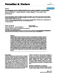
Limitations/Future Work
The methodology of broadside load is only valid for the simple scan methodology. Off late, with a aim to reduce test vector data volume, ATPG methodologies with pseudo random pattern generators along with the scan methodologies have been introduced – Logic BIST (see Figure 6). The scan chains are loaded internally and not applied from the periphery. The seed data is loaded from the periphery. The pseudo random pattern generator (PRPG) then operates on this seed and generates values to be loaded into the flops. After the data has been captured, the scan chains are not directly scanned out but the values are aliased into a multiple input signature register (MISR). The MISR is scanned out and the comparisons are made. The test vector file does not have any information about the internal scan structure or the values to be loaded into each of the flops in the design. The file has the data to be loaded into the seed and the data to be observed at the MISR only. Test vectors for such methodologies cannot be simulated using broadside load methodologies. Serial simulation of the test patterns offers the only but highly unviable solution. New techniques for faster simulation of these patterns need to be developed.
Glossary
[6] [7] [8] [9] [10] [11] [12] [13] [14] [15] [16]
Automated Test Equipment Automatic Test Pattern Generation Programming Language Interface Open Verilog International Test Description Language Standard Delay Format Standard Test Interface Language Verilog Procedural Interface
References Int. Technology Roadmap for Semiconductors, Sematech, Nov. 1999. M. Shimuzu et al., “100 Mhz Algorithmic pattern generator for memory testing”, IEEE Int. Test Conf., pp. 56-67, 1980. U. Schoettmer et al., “Challenging the ‘High performance – High cost’ paradigm in Test”, IEEE Int. Test Conf., pp. 870-879, 1995. Jerry Katz et al., “A new paradigm in test for the next millennium”, IEEE Int. Test Conf., pp. 568476, 2000. M. Roncken, “Testing asynchronous chips”, Israel Workshop on Asynchronous VLSI, pp. 336-339, Mar 1995. E. C. Crockford, “Solutions to the problems of test vector translation”, Computer Aided Test and Diagnosis, IEE Colloquium, pp. 4/1-4/3, 1988. Rochit Rajsuman, “Extending EDA Environment from Design to Test”, 11th Asian Test Symp., 2002. Standard Test Interface Language, IEEE standard 1450, 1999. Texas Instruments, TI TDL Manual. IMS Inc., Waveform Generation Language, TDS documentation. IEEE Standards Association, Extensions to STIL for Tester Target Specification, PAR for P1450.3. “What do gate-level sims buy you these days?” – ESNUG 420, Item 1, 12/10/03, www.deepchip.com Gregory A. Maston, “Considerations for STIL Data Application”, IEEE Int. Test Conf., pp. 290-296, 2002. John Cooley et al., “Writing Verilog models for Simulation performance, Synthesis and other CAE tools”, OVI – Verilog HDL Conf., Mar 14 1994. Verilog Programming Language Interface, IEEE standard. 1364-1995. Stuart Sutherland, “Transitioning to the new PLI standard”, Int. Verilog Conf., Mar 1998. Paper 38.3 1107