fixedly couples D, G and I. In figure am mentioned principally .... trok e of effec ter elem ents. , [m m. Stroke of element KN. Stroke of element H(L)MJ. BRAKING.
Proceedings of the 13th WSEAS International Conference on SYSTEMS
Simulation Results Regarding to Cinematic Parameters of Mechanical Systems MARIUS ARDELEAN, ERIKA ARDELEAN, TEODOR HEPUT, ANA SOCALICI Engineering and Management Department Polytechnic University of Timisoara Revolutiei street, no 5 Hunedoara, cod 331128 ROAMANIA {marius_a, erika_a, heput, socalici_a}@fih.upt.ro Abstract: - The braking mechanisms from the bar mills frame have a higher complexity. In mechanisms acts differently types of forces, such as motor forces and moments, the useful and passive resistant forces and moments (how I am the frictions from kinematics couple of ale the mechanisms), forces and moments of inertia, forces of weight, bond strengthens (the reactions from couple of mechanisms). These forces and moments are necessary in sight of the kinematics elements and couple dimensioning of all mechanisms and verification calculus of motor power. Thus is very important as in design phase to know operation of equipment below influence of useful and dynamic loads. With this point of view, besides the experimental measuring of accelerations are achieved simulations using this type of specialized software called SAM (Simulation and Analysis of Mechanism) but also simulation obtained based on analytic solution of the mechanism equation. Finally is made comparison between all of this three getting methods of kinematics parameters studied mechanism. Key-Words: - simulation, kinematic parameters, acceleration In mechanisms theory are known grafo-analytic, analytic and simulation kinematics analysis method. Grafoanalytical methods are expeditious and simple to use, only that by reason of lot of graphic representations accuracy results is low. Analytic method, involve an great number of mathematical calculus, respectively system solution of equation must be calculated for how much the many position of leading elements, what can be very resolvable through the utilization of personal computer and mathematical software. Simulation method involves utilization of specialized simulation software made based on finite differences method
1 Introduction Kinematic analyses of mechanisms has as aim the determination position, speeds and accelerations of a mechanism elements (position angles, speed and angular acceleration in case of elements with rotation and movements, speed and linear acceleration in case of elements with translation) depending on the angle of position of leading elements of his rotation or linear movement in case which leading element executes the translational motion. When kinematic elements execute rotational or planeparallel motion, through the knowing of his position, speeds and angular accelerations, can be calculated the trajectories, speed and linear accelerations of different characteristic point of this elements, depending on the leading elements position For easy effectuation of plan mechanisms kinematic analyses, is necessary the transformation of mechanisms, if is applicable, through the substitution of superior kinematic couples, of IV classify, with kinematic element and inferior kinematic couples, of V classify as well as the divide of mechanisms in kinematic ASSUR group and leading element, because most methods of kinematics analysis, in order to can them easily generalize were elaborate for such kinematic group (dyad, triad, tetrad, etc.)
ISSN: 1790-2769
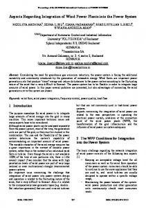
2. Modelling the mechanism The kinematics scheme of mechanism is presented in figure 1. The mechanism is appertain to a plan reference system, with origin in the fixed articulation A, with OX axis oriented with a parallel direction to the direction of fixedly couples D, G and I. In figure am mentioned principally dimension and extreme position of mechanism. The geometric element of the first brake mechanism is: AB=143mm, BC=1800mm, CD=350mm, CE=640mm, EG=350mm, GH=187mm, EF=430mm, FI=350mm, IJ=187mm, JK=135mm, HL=150mm, JM=150mm, ML=430mm, KN=181mm, IN=287mm and angular velocity ω1=2π rad/s.
254
ISBN: 978-960-474-097-0
Proceedings of the 13th WSEAS International Conference on SYSTEMS
Ns Ls
Ld
Ms Ks
Hs
D
G
Md Js
Nd
Hd
I
Jd Kd
Es
Cs Cd
A
Fs Ed
Fd
Figure 1. Schematic of first brake mechanism.
α s = π + (γ − p DAC s )
This is a plan mechanism [1], and is made from 11 kinematic mobile elements and 15 kinematic couples of V classify (he formed you quadrangular A,B,C,D; the dyad C,E,G; the dyad E,F,I; the dyad H(L)MJ; the dyad K,NN) and slidable couple in P. Plan mechanisms are mechanisms of family f=3, the degree of mobility for plan mechanisms are: M3=3·n-2·C5-C4=3·11-2·16-0=1 (1) The representation in this two extreme position is made in AutoCAD, to the scale, so that the proper angles of right extreme position (represented with blue) and respective left (represented with red) results simple through drawing the dimensions of respective angles. Coordinate of fixed articulation D, G and I are: xD=1840mm, xG=2480mm, xI=2910mm, yD=420mm, yG=420mm, yI=420mm Length of AD:
AD = x D2 + y D2
(6) The position angle of crank for extreme right position of the mechanism:
α d = γ − p DACd
7) Measure of rotation angle of the crank AB in active stroke: αa = 2 ⋅ π − αs + αd (8) Measure of rotation angle of the crank AB in passive stroke: α p = αs − αd (9) The position angle of swing lever DC in extreme left position: Ψs = γ + p ADC s (10) The position angle of swing lever DC in extreme right position: Ψd = γ + p ADCd (11) Pendulum angle of swing lever DC: Ψo = Ψd − Ψs (12) Presented mechanism works in two phases, first phase when laminate is braked through friction with the effecter element (the mobile “trough”) H(L)M, respectively secondary phase when laminate is elevated of the second effecter element KN and is pushed to the clutches of deliver. The theoretical stroke of this two effecter elements are presented the in figure 2, and make a point, to angle of the crank where the mechanism can be stopped for braking laminate. Is noticed for position angles of the crank under 600, the position of N couples found out below the position of M couples, [2].
(2)
Position angle γ:
γ = arctg
yD xD
(3) Extreme position left and right is produced when the crank and the rod overlapped and respectively, crank and rod are in extension, and angles are: 2
p DAC S , d
AD 2 + ACS , d − DCS , d = arc cos 2 ⋅ AD ⋅ ACS , d 2
p ADCS , d = arc cos
AD 2 + DCS , d − ACS , d 2 ⋅ AD ⋅ DCS , d
2
(4) 2
(5)
The position angle of crank for extreme left position of the mechanism:
ISSN: 1790-2769
255
ISBN: 978-960-474-097-0
Proceedings of the 13th WSEAS International Conference on SYSTEMS
The oretica l stro ke of effe cte r e leme nts, [mm]
Stro ke o f e l em en t H (L )MJ
This angle corresponds to the pause position of mechanism according first work phases (braking). For position angles of crank bigger of 600 the mechanism enters into secondary work phases, when laminate is elevated.
Stro ke of e le me nt KN
3 00 2 70 2 40 2 10 1 80
3. Simulation mechanism
1 50 1 20 90
30 0 30
60
90
120 150 180 210 2 40 27 0 30 0 330 360
Pos ition a ngle of cr ank , [degree s]
Figure 2. The theoretical stroke of effecter elements according as position angle of crank. Stroke of element KN
Stroke of element H(L)MJ
Real stroke of effecter elements, [mm
300 270 240 210 180 150 120 90 BRAKING 60 30 0 0
0,15
0,3
0,45
0,6
0,75
0,9
1,05
1,2
1,35
presented
1,5
Time, [s]
Figure 3. The real stroke of effecter elements.
Figure 4. Component of speed and acceleration according with position angle of crank, for J couple according with time.
ISSN: 1790-2769
model
For simulation of mechanism is utilized the software product called SAM (Simulation and Analysis of Mechanism). This is a software interactive product designed for study of the plan mechanisms. So mechanism designed in AutoCAD is imported in SAM, where with fixed cinematic elements is build mechanism and is fixed the elements where are not moving. Also is attributed to the crank movement law, accorded to the real movement law of motor element of mechanism. Movement law is linear, position angle of crank are between 0 and 3600, angular speed of leading element are constant and angular acceleration is equal to 0 ( is considered the real mechanism in stabilized work phases, not in starting phases). By reason of constructive originalities and the symmetry of elements are shall present just a part of movement law (for representative couples), due to duration of theoretic cinematic cycle according to position angle of crank, [2]. This dependence is presented in figures 4 and 5.
60
0
of
256
ISBN: 978-960-474-097-0
Proceedings of the 13th WSEAS International Conference on SYSTEMS
Figure 5. Component of speed and acceleration according with position angle of crank, for K couple. made a “contact panel” for all eight acquisition channel. Acquisition of data it was made in analogical format, the accelerometer permits the simultaneous measure of accelerations components after two axes of coordinates systems of reference (mechanism is a plan mechanism). For data acquisition are used a C++ program. The calibrations of accelerometer are made from producer’s specification, conversion of voltage into acceleration are made with two Excel routine. The experimentations they accomplished on the experimental model make to the scale 1:1 after the industrial mechanisms. Engine used to carrying away mechanism is a direct current engine with power of 1,4KW, at which moderate rotation speed with a tachometer mounts on axle and set to a value of 1200 rot./min. Also are using a gear reduction unit with report:
4. Measurements made on laboratory model Cinematic parameter (acceleration) was measure with an accelerometer made with ADXL202JQC circuit, [3]. This type of accelerometer has as much come out for the digital signal and also analogical signal. The input current for accelerometer is from a source of 4,5V direct current. For a quick and easy fixations, on the opposite part incorporate circuits is located a magnet. Previously establishing this way of fixation they did the experimentations in order to put in evidence the possible influence of magnetic field about behaviour in operates of accelerometer. As well, in order to don't obtain the measures errors, he assured coupled against turning around in time of work. In figure 6 is presented this way of fixation.
i=
nout
=
20 1
(13)
Thus rotation speed of crank mechanisms has the value of 60rot./min, like in simulation and industrial activity. Measurements have been made for many cinematic cycles, from this cycle are selected representative cycle and are present in graphical dependences. In graph can be observed small variation of cinematic parameters results from vibration in functioning of laboratory mechanism. Due to constructive peculiarities of mechanisms, parallel and equal element can be affirmed as certain couple has same motion. In this way can be sad as the C, E and F couple is moving after same law, and also J, H and M couples have same type of movement. For B couple, the data was inconclusive because data was acquired in just in starting phases of installation (not in stationary phases).
Figure 6. Mode of fixation for accelerometer on studied couple
In order to acquisition and transmits data from accelerometer to computer, respectively digital or analogical signal, we are used an acquisition data plate specialized in interfaces of digital computer with exterior electric circuit. For this acquisition data plate it was
ISSN: 1790-2769
nin
257
ISBN: 978-960-474-097-0
2
Acceleration components, [m/s ]
Proceedings of the 13th WSEAS International Conference on SYSTEMS
6,0 5,0 4,0 3,0 2,0 1,0 0,0 -1,0 -2,0 -3,0 -4,0 -5,0 -6,0
classic method of kinetostatic analysis, mechanism is solved through the classical method based on vectorial contour method, what involve a voluminous number of computing, carry must rewrite in case a study of new mechanism.
ax
a
ay
0
40
80
p
120 160 200 240 280 320 360
Position angle of crank, [degree]
2
Acceleration components, [m/s ]
Figure 7. Component of acceleration according with position angle of crank, for C couple. 7 6 5 4 3 2 1 0 -1 -2 -3 -4 -5 -6
Figure 9. OY component of acceleration according with position angle of crank, for N couple.
ax
ay
0
40
80
120 160 200 240 280 320 360
Position angle of crank, [degree]
Figure 8. Component of acceleration according with position angle of crank, for N couple. Figure 10. OX component of acceleration according with position angle of crank, for M couple.
Also is recorded acceleration for K an N couples. In figure 7 and 8 is presented acceleration components measured for both axes in case of C and N couples.
5. Conclusion The cooling beds of small profile rolling mills have a very important role in obtaining of a finite product of a high quality. These cooling beds assure a conducted cooling of laminated profiles at the same time wish straightening them during the crossing of the cooling bed reliability, a diminution of exploitation costs. For this three analysis methods (calculated values, measured values and simulated values) will be sketched the variation curves of the acceleration components by joining the obtained points, without approximating the trajectory by interpolation polynomial curves. In the analytical calculation, an analytical solution of the equations will be obtained by successive iterations. In
ISSN: 1790-2769
Figure 11. OY component of acceleration according with position angle of crank, for M couple.
258
ISBN: 978-960-474-097-0
Proceedings of the 13th WSEAS International Conference on SYSTEMS
The utilized simulation program SAM has the mathematical core built on the basis of the finite differences, quite an accurate method, but which has as a critical problem the accuracy of the solution during the integration that depends on the equation type with finite differences and on the thickness of the network of established discretion. The method is more efficacious simple to use, but is necessarily advance knowledge in design work. Kinematics parameters can be measured directly from studied machine, especially when have this miniaturized accelerometer. Can be made a portable accelerometer based on this type of iMEMS®microintegrated circuit, microprocessor and RAM memory, can be able to store data until are downloaded to a personal computer In the case of the data measured on the empirical stand, the differences that appear could stem from the geometrical-constructive errors, from the way of adjusting the speed of the training engine and from the eventual errors of positioning of the accelerometer on the studied thimble. There are also errors that appear when the accelerometer feels the slight vibrations of the entire body of the empirical model. From figure 9, 10 and 11 were is presented the kinematic parameter for effecter elements, braking element and pulling up element, results differences between this tree method smaller of 5%, in study or design of mechanism can be used with better result simulation method.
[2] Ardelean M., Ardelean E., Heput T., Socalici A., Kinetostatic analysis method for braking mechanism, International Symposium about Forming and Design in Mechanical Engineering KOD 2008, Novi Sad, Serbia, 2008, pg.187-190, ISBN 978-86-7892-104-9. [3] Ardelean, M., New method and techonolgy for measure of acceleration, Annals of the Oradea University, Fas of Management and Technological Engineering, Vol. VII(XVII), 2008, pg.1196-1201, ISSN 1583-0691. [4] Ardelean E., Ardelean M., Prejban I., Researches regarding of using engineering plastic product in cooling bed rolling mill construction, 11th International Research / Expert Conference „Trends in the Development of Machinery and Associated Technology” TMT 2007, Hammamet, Tunisia, pg.867-870, ISBN 9958-617-30-7. [5] G. Fried, K. Djouani, D. Borojeni, S. Iqbal, Jacobian matrix factorization and singularity analysis of a parallel robot, WSEAS Transaction on Systems, june 2006, Vol 5/6, pp: 1482-1489. [6] Ion I., Vladareanu L., Simionescu I., Vasile A., 2008.The gait analysis for modular walking robot MERO walk on the slope Proceedings of the 9th WSEAS International Congress on Automation and Information (ICAI ‘08) pp 222-229, 21-24 June, Bucharest, Romania. [7] Mihai Tofan, Sorin Vlase, Horatiu Teodorescu, On the Kinematic Identification of the Hurdles Race using Cardan’s Rotation, WSEAS TRANSACTIONS on APPLIED and THEORETICAL MECHANICS , Issue 2, Volume 1, December 2006, ISSN 1991-8747. [8] Vladareanu Luige, Open Architecture Systems for the Compliance Robots Control, WSEAS Transactions on Systems, issue 9, Volume 5, September 2006, ISSN 1109-2777, pg. 2243-2249.
References: [1] Ardelean M., Ardelean E., Heput T., Socalici A.,Vilceanu L., New methods and analysis functioning techniques for cooling bed tool of the profile laminators, Metalurgia International, nr.5, 2008, pg. 49-53, ISSN 1582 – 2214.
ISSN: 1790-2769
259
ISBN: 978-960-474-097-0