Environ. Eng. Res. Vol. 13, No. 1, pp. 19 ~27, 2008 Korean Society of Environmental Engineers
Simultaneous Biofiltration of H2S, NH3 and Toluene using an Inorganic/Polymeric Composite Carrier Byoung-Gi Park, Won Sik Shin1, and Jong Shik Chung† Department of Chemical Engineering, POSTECH, San-31, Hyoja-Dong, Pohang, Gyungbuk 790-784, Korea 1 Department of Environmental Engineering, Kyungpook National University, Daegu 702-701, Korea Received August 2007, accepted January 2008
Abstract Simultaneous removal of ternary gases of NH3, H2S and toluene in a contaminated air stream was investigated over 180 days in a biofilter. A commercially available inorganic/polymeric composite chip with a large void volume (bed porosity > 0.80) was used as a microbial support. Multiple microorganisms including Nitrosomonas and Nitrobactor for nitrogen removal, Thiobacillus thioparus (ATCC 23645) for H2S removal and Pseudomonas aeruginosa (ATCC 15692), Pseudomonas putida (ATCC 17484) and Pseudomonas putida (ATCC 23973) for toluene removal were used simultaneously. The empty bed residence time (EBRT) ranged from 60 - 120 seconds and the inlet feed concentration was 0.0325 g/m3 - 0.0651 3 3 3 3 3 g/m for NH3, 0.0636 g/m - 0.141 g/m for H2S, and 0.0918 g/m - 0.383 g/m for toluene, respectively. The observed removal efficiency was 2% 98% for NH3, 2% - 100% for H2S, and 2% - 80% for toluene, respectively. Maximum elimination capacity was about 2.7 g/m3/hr for NH3, > 6.4 g/m3/hr for H2S and 4.0 g/m3/hr for toluene, respectively. The inorganic/polymeric composite carrier required 40 - 80 days of wetting time for biofilm formation due to the hydrophobic nature of the carrier. Once the surface of the carrier was completely wetted, the microbial activity became stable. During the long-term operation, pressure drop was negligible because the void volume of the carrier was two times higher than the conventional packing materials. Keywords: Biofiltration, BioMTM, Carrier, Microorganism, Odor, VOC
1. Introduction 1
Biofiltration technology has a promising potential as an effective and economical treatment technology than the traditional treatment technologies for treating contaminated air stream with low concentration of odorous compounds and/or volatile organic compounds (VOCs). The fundamental principle of biofiltration of polluted air is that gaseous pollutants are destroyed in the process being converted into carbon dioxide, water and biomass by microbial metabolic reactions. During the biofiltration, polluted air is passed through the biofilter medium where the pollutant is transferred from the gas to the liquid-solid phase where 1) they are degraded by biofilm. The concept of biofiltration to treat waste gases is similar to other forms of biological wastewater treatment. In biofiltration, a fan or blower forces gases containing biodegradable odorous compounds and VOCs through a packed bed that contains an †
Corresponding author E-mail:
[email protected] Tel: +82-54-279-2267, Fax: +82-54-279-5528
unsaturated solid medium that supports a biologically active aqueous layer. As contaminated air flows through the support medium and the aqueous biofilm, contaminants partition to the aqueous or solid phases where VOCs are transformed by microorganisms into inert products such as carbon dioxide, water, and biomass. Biofiltration primarily depends on the choice of the packing material. A proper packing material should have favorable conditions such as high porosity, appropriate pore size and suitable surface area for microbial growth and lower clogging effect that involves biofilter systems operated for long periods of time.2,3) While packing media used in conventional biofilter beds consist mostly of peat or compost, a wide variety of other materials have been used. These include soil, wood chips, bark, sawdust, activated carbon, ceramic, ground tires, polystyrene beads and poly2,4-11) In addition to the primary support medium, urethane foam. a variety of additives may be used including bulking agents, 12) buffers, nutrients, and microorganisms. Biofiltration generates the least amount of secondary pollutants such as particulates, dioxin, SOx, NOx, and CO2 and 13-23) requires minimum efforts for operation and maintenance.
20
Byoung-Gi Park, Won Sik Shin, and Jong Shik Chung
Deodorization and detoxification of volatile organic compounds (VOCs) in the air stream are the typical application of the biofiltration. Among the sources of air pollutions, H2S and NH3 are the most typical odorous compounds often encountered in industrial or residential areas.13-15,17-26) H2S and NH3 are toxic and can cause malodorous nuisances, while toluene is a suspected carcinogen. The lowest value of smelt level for H2S is 0.00047 ppmv.27) According to the toxicity report, H2S can break down the central nervous system at the concentration level of 100 ppmv. Even more seriously, H2S is eventually deadly toxic at the concentration above 100 ppmv.28) The threshold value of 29) smelt level for NH3 is 50 ppmv in the open air. NH3 is known to irritate eyes and throat. In Korea, the current regulation levels are 2-10 ppmv for H2S and 50-100 ppmv for NH3 depending on the regions and sources of the pollutants. Toluene is not yet exclusively controlled, nevertheless, toluene is controlled as a part of total VOCs or benzene derivatives, and their legally allowed 30) level is 30 ppmv in the open air. The toluene is a Title III toxic compound of the 1990 Clean Air Act Amendment proposed by US EPA.21) Recently, numbers of research works have been focused on the removal of malodorous gases. However, up to now, most of researches on the biofiltration are limited to single or binary con15,16,31-36) which seems to be impractical for real industaminants, trial application. This is because most of the emission sources contain multiple contaminants including sulfur and nitrogen compounds as well as VOCs. Cox et al. investigated on the treatment of the binary toluene-H2S containing waste air using bio-trickling beds.19) The H2S removal efficiency was nearly 100%, however, the toluene removal was much less; only 75% at pH 7.0 and 25% at pH 4.5. For the simultaneous removal of NH3 and H2S, the removal efficiency widely varied depending on the experimental conditions and the supporting media. The removal efficiency ranged from 80% to 100% for NH3 and from 90 to 100% for H2S. Malhautier et al. observed that elemental sulfur and sulfate were the products of H2S oxidation and subsequently 20) reduced the void fraction of the biotrickling bed. Kim et al. reported that microbial activity decreased due to accumulation of sulfur on the surface of packing materials during a long-term 15) operation of packed-bed biofilter system. Chung et al. also reported that the substrates (i.e., NH3 and H2S) have inhibitory effect on the removal efficiency when the concentrations of the 26) H2S and/or NH3 are relatively high. Liu et al. also reported on the inhibitory effect of a biofilter system treating binary gases 17) of toluene and ethylacetate. In this study, the simultaneous removal of ternary gases of NH3-H2S-toluene in a packed-bed biofilter was investigated using a new inorganic/polymeric composite carrier as a packing 14) material. The removal efficiency and elimination capacity were carefully examined at various inlet loadings and gas concentrations during unsteady and steady state operations.
2. Materials and Mathods 2.1. Microbial Fixing Carrier
TM
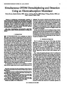
A commercial inorganic/polymeric composite carrier (BioM ) 14) was provided by Envichem Co., Ltd, Ulsan, Korea. This carrier has been used as a fluidizing carrier in an aerobic bioreactor for wastewater treatment system mainly because it has an extremely large void space (bed porosity = 0.80-0.86) compared to other conventional carriers. The composite packing material showed no pressure-drop due to the large void volume, while it kept the same levels of removal activities observed from the conventional packing materials during a long-term operation of biofiltration systems. Fig. 1 shows a photograph of the microbial fixing carrier. The physicochemical properties of the HDPE chips are summarized in Table 1. The carrier is black in color and has tubular shape with lattices. The major component of the carrier is high-density polyethylene (HDPE). Several inorganic powders (e.g., activated carbon, zeolite, clay and slag) were embedded into the HDPE in order to provide a sufficient adsorptive property toward the treating gases and habitats to microorganisms. The density of fresh carriers was adjusted to 0.97-0.98 g/cm3 by adding density-controlling materials.
Fig. 1. A photograph of BioMTM carrier. Table 1. Physicochemical properties of the composite carrier Properties Value Unit Remark -2 1.0×10 m Controlled Diameter, dp 1.0×10⁻² m Controlled Length, Lp 3.0×10⁻⁴ m Controlled Thickness, tp Surface area, Sg Bed porosity, εbed Specific surface, As Particle density, Packing density,
4.47×10⁻³ 0.80-0.86 1,000 5 5 9.70×10 -9.80×10 1.0×10⁵
m2/g 3
Measured 3
m /m 2 3 m /m 3 g/m g/m3
Measured 6(1-εbed)/dp Controlled Measured
2.2. Biofiltration System A schematic of the lab-scale biofiltration system used for the simultaneous removal of ternary NH3-H2S-toluene mixtures in the air stream was depicted in Fig. 2. The biofilter column was made of a 4-cm-id and 110-cm-long transparent Pyrex glass. The column was packed with a commercial inorganic/polymeric
Simultaneous Biofiltration of H 2S, NH 3 and Toluene using an Inorganic/Polymeric Composite Carrier
composite carrier. The actual packing length of the carrier was 0.80 m and was equally divided into three layers. A spacer (5cm-long) made of a stainless steel mesh screen was inserted between the layers to support the chips. The total bed volume of the carrier packing was 1.0 liter. A sampling port was installed at the middle point of the each section in order to allow sampling of the microbial support material and to measure gas concentrations. At the bottom of the biofilter column, a 100-mL water reservoir was placed through which inlet feed gas was bubbled. Any water collected and remaining excess was continuously drained out of the reservoir. A portion of the feed air was passed through a water saturator containing double-distilled water to provide moisture and the other portion through a toluene (J. T. Baker, 99.7%) saturator. The two streams were mixed together before being introduced into the bottom of the biofilter column. The relative humidity was maintained above 95%. The H2S (Doekyang Energen Co., 1 mol% balanced with N2) and NH3 (Doekyang Energen Co., 1 mol% balanced with N2) gases were separately fed into the biofilter column from the gas cylinders. The physical properties of the contaminant gases are summarized in Table 2. The volumetric flow rates of all gas streams were controlled by pressure regulators and rotameters. Finally, the treated air was released from the top of the biofilter column. 2.3. Operation of the Biofiltration System The biofiltration system was continuously operated for 185
days at room temperature and atmospheric pressure. No pressuredrop was observed during the operation of the biofiltration system. Total volumetric air flow rate was maintained at 0.030 and 3 0.060 m /hr that corresponds to 60 and 120 sec of empty bed residence time (EBRT). The feed concentration was about 0.0325 - 0.0651 g/m3 for NH3, 0.0636 - 0.141 g/m3 for H2S and 3 0.0918 - 0.383 g/m for toluene, respectively. The inlet loading 3 3 (IL) was 1.060 - 2.970 g/m /hr for NH3, 1.909 - 6.364 g/m /hr for 3 H2S and 3.444 - 18.828 g/m /hr for toluene, respectively. The initial pH was adjusted to 7.0 by using NaOH and HNO3. 2.4. Measuring of Performance on the Biofiltration System Conventionally, the performance of the biofiltration system can be characterized by several measuring factors. They are (i) 3 the inlet loading of the pollutant gas component (IL, g/m /hr), 3 (ii) the elimination capacity (EC, g/m /hr), (iii) the empty bed residence time (EBRT, seconds) and (iv) the removal efficiency (X, %). Among the factors, IL, an actual burden applied on the system, is defined as the total volumetric flow rate of the feed multiplied by the inlet concentration of the pollutant gas. The EC is the actual removal capacity of the contaminant gas within the biofilter bed. It is usually less than IL, but is equal to IL when 100% removal is achieved. The EBRT is an imaginary residence time, assuming that the packed column is empty. The X is the conversion of the target gas component that shows how much of the pollutant gas is removed in the biofilter bed. The factors are defined as: EBRT =
ILi =
ECi =
Xi =
Fig. 2. A schematic diagram of the biofiltration system.
(C
(C
VB q0
(1)
CiG, IN (2)
EBRT
G i , IN
− CiG,OUT
) (3)
EBRT
G i , IN
− CiG,OUT
CiG, IN
) = EC
i
IL i
(4)
where C (g/m3) is the concentration in the gas phase, q0 is the 3 inlet volumetric gas flow rate (m /hr) and VB is the packed-bed 3 volume (m ). Superscript G represents the physical properties observed in the gas phase, subscript i is the gas component (i.e., NH3, H2S and toluene) and subscripts IN and OUT indicate the
Table 2. Thermodynamic properties of gas components in pure water at 298.15 K and 1 atm Solubility MW Henry’ law constant, Gas (g/m3) (g/mol) Hi a (dimensionless) 17.03 1,387 953,680 NH3 H2S 34.08 2.43 3,340 Toluene 92.14 3.96 14,740 Note: aHi = Ci,liquid/Ci,gas and bData obtained from references 34, 41-43.
21
Overall mass transfer coefficientb, (KLa, hr-1) 623-7,344 15-24 54-72
22
Byoung-Gi Park, Won Sik Shin, and Jong Shik Chung
inlet and outlet conditions, respectively. 2.5. Analytical Methods Both the inlet and outlet concentrations of NH3, H2S and toluene gases were measured by using gas detection tubes (Model 3La, 4L and 122L, Gastec Co., Japan). The effective detection range of the tube was 2.5-200 ppmv for NH3, 1-120 ppmv for H2S, and 1-100 ppmv for toluene. The lowest detection limit was 0.5 ppmv for NH3, 0.2 ppmv for H2S, and 0.5 ppmv for toluene. The residuals, pale yellow colored cakes, formed on the carrier surface and in the drain water were characterized using X-ray powder diffraction (XRD, MAC Science Co., Model M18XHF, CuK) and an elemental analysis (LECO Co., Model CHNS 932). The bed porosity of the carrier was measured by a mercury porosimeter (Microstructure Lab., Carlo Erba Strumentazione). The BET surface area was measured by nitrogen adsorption using a surface area analyzer (Micromeritics, Model ASAP 2021C). 2.6. Microorganisms Three different types of microorganisms were independently cultivated in aqueous mineral solutions using a shaking incubator (Jeio Tech, SI-900R) at 30°C and 100 rpm. The nitrifying bacteria, Nitrosomonas and Nitrobactor, were isolated from the activated sludge in a sewage water treatment facility located at POSTECH, Pohang, Korea. The nitrifying bacteria were grown in a mineral nutrient medium prepared by dissolving 0.2357 g of (NH4)2SO4, 0.080 g of KH2 PO4, 0.020 g of MgSO4 and 0.0085 g of Fe2(SO4)2‧H2O dissolved in 1.0 L of double distilled water. A H2S degrading bacterium, Thiobacillus thioparus (ATCC 23645), was obtained from the Korean Collection for Type Cultures (KCTC). The organism was cultivated in a mineral medium (ATCC medium 290 S6) prepared by dissolving 1.2 g of Na2HPO4, 1.8 g of KH2 PO4, 0.1 g of MgSO4‧7H2O, 0.1 g of (NH4)2SO4, 0.03 g of CaCl2, 0.02 g of FeCl3, 0.02 g of MnSO4, and 10.0 g of Na2S2O3 in 1.0 liter double-distilled water. For the toluene degradation, Pseudomonas aeruginosa (ATCC 15692), Pseudomonas putida (ATCC 17484) and Pseudomonas putida (Pseudomonas arvilla, ATCC 23973) were also purchased from the Korean Collection for Type Cultures (KCTC). The Pseudomonas aeruginosa was grown in ATCC medium 129 containing 0.5% NaCl, 3.0 g of beef extract and 5.0 g of peptone. The Pseudomonas putida (ATCC 17484) was incubated in ATCC medium 3 containing 3.0 g of beef extract and 5.0 g of peptone in 1.0 L of double- distilled water at pH 6.8. The Pseudomonas putida (ATCC 23973) was cultivated in ATCC medium 1271 containing a benzoate nutrient medium containing 3.0 g of (NH4)2PO4, 1.20 g of KH2PO4, 5.0 g of NaCl, 0.20 g of MgSO4‧ 7H2O, 0.50 g of yeast extract, 3.0 g of sodium benzoate (filtersterilized) in 1.0 L of double-distilled water. All culture media were autoclaved at 121°C for 15 min prior to use. After cultivation, the microorganisms were mixed together immediately before inoculation. The mixed microorganisms were sprayed over the carriers in an open vessel with aeration
for several hours. The inoculated carriers were then packed into the biofiltration column and acclimated for the next two weeks. The inlet loadings (IL) of NH3, H2S and toluene, were kept at a quarter of those used for normal operating conditions. 2.7. Microbiological Analysis In order to count the microbial populations of Nitrosomonas, Nitrobactor, Thiobacillus thioparus and Pseudomonas putida, th the colony-forming unit (CFU) was measured at the 105 day of operation by employing the conventional most probable number method (MPN).36,37) A portion of three different biofilmdeposited on carrier samples were collected from the upper, middle and lower sampling port attached on the biofilter column. The microorganisms attached on the carrier samples were separated by vortexing for 2 min in a centrifuge tube containing a basal salt medium. The salt medium was prepared by dissolving 2.5 g of (NH4)2SO4, 0.5 g of KH2PO4, 50 mg of MgSO4‧7H2O, 4 mg of CaCl2‧2H2O, and 0.1 mg of Fe-EDTA in 1.0 liter doubledistilled water with pH 8.0-8.2 and autoclaving at 121°C for 15 minutes. The microorganisms were collected by centrifugation at 10,000 rpm for 20 min and then resuspended in 10 mL of the salt medium. 0.5 mL aliquots of the homogenized suspension were diluted 10 times in serial test tubes containing 4.5 mL of the salt medium and shaken. The final dilutions were spread onto petri plates containing each medium with nutrient agar described previously. Subsequently the samples were incubated for 21 days at 30°C in an incubator (Jeio Tech, SI-900R). After 21 days of incubation, the agar plates were scored. The values for the microbial populations were finally obtained by referring to the MPN table.
3. Results and Discussion 3.1. Removal Efficiencies Fig. 3 shows the results of a long-term operation of the biofiltration system for the simultaneous removal of NH3, H2S and 3 toluene. The inlet air flow rate was maintained at 0.030 m /hr th nd from the 0 day to the 102 day and then increased to 0.060 m3/hr from the 103rd day to the 180th day, and the corresponding EBRT was 120 sec and 60 sec, respectively. As summarized in the Table 1, the bed porosity was > 0.80 and the feed concentration of NH3, H2S and toluene was 0.033 - 0.065, 0.064 - 0.141, 3 0.092 - 0.383 g/m , respectively. The corresponding IL for NH3, 3 3 H2S and toluene was 1.060 - 2.970 g/m /hr, 1.909 - 6.364 g/m /hr 3 and 3.444 - 18.83 g/m /hr, respectively. As shown in Fig. 4, in the early stage of the long-term experith ments (i.e. from the start to the 5 day), all gases showed high removal efficiencies. The high removal in the early stage was mainly due to adsorption onto the packing material and mass 21,38) transfer into aqueous phase, but not due to biodegradation. However, the adsorptive effect of the carrier was lower than 9,10) th After the 5 day, the those of other conventional carriers. adsorption capacity of the biofilter column was under thermodynamic equilibrium with the pollutant gases. Since the micro-
Simultaneous Biofiltration of H 2S, NH 3 and Toluene using an Inorganic/Polymeric Composite Carrier
Fig. 3. Results of the long term operation of the biofiltration system. (a) NH3, (b) H2S, (c) toluene. Symbols: ◦ = inlet concentration and • = outlet concentration. Solid line indicates EBRT or inlet air flow rate.
organisms were not fully acclimated yet, biodegradation was not active and thus the removal efficiencies of all gases decreased until the 20th day. th The removal efficiency was gradually increased from the 20 th day to the 40 day for H2S removal. This was one of the typical characteristics of the composite carrier. Presumably, the gradual increase in the removal efficiency during this period was closely related to the increase in wetting surface area of the carrier. Physically, hydrophilic porous inorganic particles were included in the hydrophobic HDPE-based polymer surface of the carrier. Therefore, due to this physical configuration of the carrier surface, a certain period of surface wetting was required. Optical microscopic investigation revealed that during the early stage of biofilter operation, microorganism seed spots were formed near the inorganic particles that exist on the outermost surface of the carriers (Figure not shown). Once the spots were formed, the spots became enlarged and eventually formed uniform biofilm over the entire surface of the carrier. After this wetting period, the overall system response became stable for changes of the inlet conditions. A plot of elimination capacity (EC) vs. inlet loading (IL) was shown in Fig. 5. Among the gases, H2S showed a complete elimination almost over the entire range of the experimental conditions; i.e., data points lied on the diagonal line that represents 100% removal. Exceptionally, several points positioned below the diagonal line. This was because these data were measured during the early stage of and time for carrier surface wetting was not enough. In Fig. 4, the surface wetting time for H2S was
23
Fig. 4. Removal efficiency as a function of time. (a) NH3, (b) H2S, and (c) toluene. Solid line indicates EBRT or inlet air flow rate.
Fig. 5. Elimination capacity as a function of inlet loading. (a) NH3, (b) H2S, and (c) toluene. Diagonal line represents 100% removal.
24
Byoung-Gi Park, Won Sik Shin, and Jong Shik Chung
about 40 days. The removal efficiency of NH3 increased gradually from 10% to 70% from the 20th day to 80th day, and then became stable (Fig. 4). The removal efficiency of NH3 was kept at nearly constant value, i.e., > 70%, until the inlet air flow rate increased on the 103rd day. Hereafter, the removal efficiency was almost constant value of over 90%. The elimination capacity of NH3 increased as inlet loading of NH3 increased. The elimination capacity at near the inlet loading of 1.5 g/m3/hr was again the elimination capacity measured during the wetting period of time. In Fig. 4, the removal efficiency of toluene gradually increased from 10% to 40% from the 20th day to the 80th day, and became constant. About 80 days of wetting time was observed for toluene. The surface wetting time for the carrier surface to be fully covered by biofilm was 80 days for NH3 and toluene which was longer than that for H2S (40 days). In order to understand the difference in the surface wetting time for the carrier, both the residuals of drain water from the bottom reservoir and the deposited pale yellow colored cake on the carrier surface were collected on the 30th day and 131st day and analyzed by XRD and the elemental analyzer. The results revealed that the deposited pale yellow cake on the carrier surface was mainly elemental sulfur, while the residual in the drain water was ammonium sulfate (data not shown). Both the elemental sulfur and the ammonium sulfate 27,38) ((NH4)2SO4) were known as the byproducts of H2S oxidation. According to these results, it appeared that the carrier surface was quickly deteriorated by the elemental sulfur even at the very early stage of operation. As shown in the Fig. 5, microorganisms for the H2S removal were more active showing higher elimination capacity than the others and thus metabolized H2S rapidly producing hydrophobic elemental sulfur. Wetting of the carrier surface for biofilm formation was hindered by the elemental sulfur deposition, influencing the removal efficiencies of NH3 and toluene. However, the elemental sulfur deposition on the carrier surface did not affect H2S removal. According to Oyarzun et al., elemental sulfur is an intermediate of H2S metabolism and is one of substrates being further oxidized by Thiobacillus thioparus, that was used for H2S removal in this study.27) Generally, Thiobacilli species can withstand and survive when exposed to elemental sulfur and/or sulfur-containing environments. This was the main reason why the surface wetting time for H2S removal was shorter then those for NH3 and toluene removals. As shown in Fig. 4, once the carrier surface was fully covered by biofilm, the H2S removal efficiency was highly stable. nd On the 102 day, the total inlet air flow rate increased from 3 0.03 m /hr to 0.06 m3/hr. Upon this change, the removal efficiency of NH3 increased but the removal efficiency of toluene decreased, while the removal efficiency of H2S was nearly 100%. Comparison of Fig. 4 and Fig. 5 shows that that the inlet loading for the NH3 removal reached to the maximum, that for H2S removal was still far below the maximum, while that for the toluene removal was already far beyond the maximum. Besides, toluene removal efficiency was the lowest among the three gases. In part, this is attributed to the influence of elemental
sulfur and ammonium sulfate deposition on the carrier surface. Liu et al. observed that, at a certain concentration level, the removal of toluene was inhibited by presence of ethylacetate.17) Chung et al. reported that a competitive inhibition exists between the NH3 and H2S when the substrate concentrations are relatively high.14) They used the Andrews-Haldane biokinetic model account for the inhibition effect of binary substrates in 39) the biofiltration system. In this work, we intended to treat a mixture of three substrates (NH3, H2S and toluene) using a mixture of microorganisms cultured in one single column: Thiobasillus thioparus, an autotroph, for the oxidation of H2S; Nitrosomonas and Nitrobactor, autotrophs, for the degradation of NH3; and Pseudomonas putida, a heterotroph for the oxidation of toluene. Then, competitive inhibition among the three substrates may exist in this system. Therefore, we performed a biokinetic study using the Andrews-Haldane biokinetic model. The inhibition effect between the ternary substrates was analyzed by the Andrews-Haldane biokinetic model.26,40,44,45) The model is given as: ri =
µ m ,i Ci K S ,i + Ci +
Ci2 K I ,i
(5)
where ri (g/m3/hr) = the apparent removal rate of pollutant com3 ponent, i, μm,i (g/m /hr) = the maximum removal rate of a 3 pollutant component, i, Ci (g/m ) = the concentration of compo3 nent, i, KS,i (g/m ) = the half saturation coefficient for removal 3 of component, i, and KI,i (g/m ) = the inhibition coefficient for component, i. Through the kinetic study, however, we were not able to find any evidence on the competitive inhibition effect on toluene 45) removal. Our previous report showed that this linear relationship is generally observed at low levels of the substrate concentration region, where the substrate concentration (Ci) is much smaller than the half saturation constant (KS,i) in biokinetics. The Andrews-Haldane biokinetic model equation can be reduced to the pseudo-first-order reaction in the low substrate concentration region (i.e., KS,i >> Ci). In this kinetic regime, only the ratio of the maximum removal rate to the half saturation constant can be obtained. This concentration range is even far below the con45) centration range where the competitive inhibition occurs. The trends of the ECs (Fig. 5) indicate that neither reaction nor inhibition is limiting in the biofiltration system within the tested conditions. In addition, our results are consistent with those of others26,45) regarding the H2S removal kinetic study that uses the Andrews-Haldane biokinetic model. According to their observa26,45) , the EC increased as both the inlet flow rate and concentions tration increased, even at ten to hundred times higher flow rate and concentration than those used in this study (H2S concentra3 3 tion = 0.06 g/m up to 0.14 g/m ). The EC value increased asymptotically as the inlet H2S concentration increased. th On the 105 day, the microbial populations were measured 37,38) The microbial populaby the conventional MPN method. tions in the bottom layer were two to three orders of magnitude
Simultaneous Biofiltration of H 2S, NH 3 and Toluene using an Inorganic/Polymeric Composite Carrier
higher than those in the middle and upper layers. This is simply because more substrates are available in the bottom layer of the biofilter. 3.2. Effects of Inlet Feed Condition on the Elimination Capacity The elimination capacity of the biofilter as a function of the inlet loading for NH3, H2S and toluene was shown in Fig. 5 and the results were summarized in the Table 4. Relatively lower elimination capacities were observed when the inlet loadings were low. This was because the data were obtained during the th th 40 -80 days and thus surface wetting of the carrier was not enough. The elimination capacity of NH3 was almost linearly proportional to the inlet NH3 loading in the range of 1 g/m3/hr - 3 3 g/m /hr. The maximum value of the elimination capacity for the 3 NH3 removal was 2.7 g/m /hr within the experimental conditions. For the NH3 removal, the experimentally measured elimination capacities by pure biological reaction might be overestimated because the solubility of NH3 in water is extremely high (see Table 2). Only except the data obtained at earlier surface wetting period, all the data points for the H2S elimination capacity were positioned on the diagonal line (Fig. 5(b)). This confirms that the removal efficiency is nearly 100% within the entire experimental conditions regardless of the amount of H2S gas introduced into the biofilter. Therefore, the inlet loading of the H2S removal was still far below the maximum elimination 3 capacity (>6.4 g/m /hr). For toluene removal, microbial activity was relatively poor, and most of the data for the elimination capacities were positioned below the diagonal line. The maximum value of the elimination capacity for the toluene was about 5.0 3 3 g/m /hr at the loading of >10 g/m /hr. The relatively poor microbial activity for the toluene removal is explained by (i) the inlet loading was too high for the biofiltration system that already showed the maximum elimination capacity and (ii) the elemental sulfur deposited on the carrier surface inhibited the toluene removal and/or at least affected the time required for surface wetting. Considering the inlet concentration of toluene was higher than those of NH3 and H2S (Table 4), the microbial activities and the population of toluene degrading bacteria (Pseudomonas aeruginosa and Pseudomonas putida) were less (Table 3). Relatively weaker microbial activities and a lower population growth
rate of the heterotrophs (toluene degrading bacteria) compared to those for the autotrophs (NH3 and H2S degrading bacteria) could be another reason. During the long-term operation of biofiltration system, there was no interaction or inhibition among the three different microorganisms: Nitrosomonas and Nitrobactor, Thiobasillus thioparus, and Pseudomonas putida. The biodegradation was a parallel process where the three reactions are simultaneously occurring on the same sites of the packing materials. Although there are a lot of chances for the competitions among the three different microorganisms in terms of nutrients and byproducts of the metabolisms, the simultaneous biodegradations for the ternary NH3, H2S and toluene substrates took place independently. This was 26) in contrast to the results reported by Chung et al. for the removal on the binary NH3 and H2S gases using a biotrickling bed, 19) but in agreement with the results of Cox and Deshusses who also observed no interaction between two microorganisms during the simultaneous removal of the binary H2S and toluene in a biotricking filter. Finally, during the simultaneous biofiltration of ternary gases (NH3, H2S and toluene) using the composite carrier as a supporting material of the microorganisms, there was no significant pressure build-up within the packed column due to large void volume of the carrier, meanwhile most of conventional packing materials such as Zeocarbon, night soil, lava, cork, compost showed gradual increase in pressure-drop over a long-term operation. In addition, the new inorganic/polymeric composite carrier was a light, not fragile and rigid polymer and thus it was not compacted or broken down by gravity during the long-term operation. In general, the conventional packing materials for the biofilter column are occasionally replaced when the pressuredrop within the column becomes significant due to continuous accumulations of biofilm and/or the packing materials are broken down. If the biofilter column packed with this inorganic/polymeric microbial fixing carrier, the recovery process or replacement procedure is not necessary. This was the major advantage of using this commercial microbial fixing carrier. This work demonstrated that the inorganic/polymeric composite carrier was feasible for the simultaneous removal of multiple gases in a biofilter. The new composite carrier with a very large void volume may overcome the inherent problems of the conventional packing materials showing gradual pressure drop during
Table 3. Microbial populations in the biofilm fixed on the carrier Logarithmic counts for microbial populations, log (CFU/g) Column Section Nitrosomonas Nitrobactor Thiobacillus thioparu Upper 4.4 4.2 4.1 Middle 5.0 5.2 5.5 Lower 7.3 5.5 6.2
Pseudomonas putida 5.1 5.7 7.2
Table 4. Summary of the results of long term operation of biofilter Component
CinG (g/m3)
IL (g/m /hr)
X (%)
EC (g/m /hr)
NH3 H2S Toluene
0.0325-0.0651 0.0636-0.141 0.0918-0.383
1.060-2.970 1.909-6.364 3.444-18.83
2-98 2-100 2-80
0.064-2.715 0.297-6.364 0.115-6.888
3
25
3
26
Byoung-Gi Park, Won Sik Shin, and Jong Shik Chung
the long-term operations. Only a minor problem of this new composite carrier is that it requires relatively a long period of time for wetting of the carrier surface.
4. Conclusions In the evaluation of feasibility of a new inorganic/polymeric composite carrier for the simultaneous removal of NH3, H2S and toluene, no significant pressure-drop was observed; meanwhile a relatively long time for surface wetting was required. Pressure-drop and gradual compaction by gravity or air stream were prevented by the inherent physical nature of the new inorganic/polymeric composite carrier during the long-term operation of the biofiltration system. Interruptions in a biofilter operation often caused by the pressure-drop can be improved by introducing the composite carrier. Once the surface of the carrier was fully wetted, the system showed the same level of removal activity as the other conventional carriers. In addition, there was no competitive inhibition among the different microorganisms. Therefore, the new inorganic/polymeric composite carrier is feasible in the development of the single-stage biofiltration system for the simultaneous removal on the trace amount of ternary NH3, H2S and toluene. In design and stability aspects, 3 this system can be operated up to inlet loading of 2.7 g/m /hr 3 3 for NH3, 6.4 g/m /hr or even higher for H2S and 5.0 g/m /hr for toluene, respectively. The removal efficiencies of above 98% for NH3 and nearly 100% for H2S were achieved, however, the toluene removal efficiency was relatively low (about 40%), because the tested inlet concentration was too high.
Ackowledgement The authors would like to appreciate for the financial support of this study provided by Korean Ministry of Science and Technology (MOST).
References 1. Devinny, J. S., Deshusses, M. A., and Webster, T. S., Biofiltration for Air Pollution Control, CRC Press, Boca Raton, FL, USA (1998). 2. Moe, W. M., and Irvine, R. L., “Polyurethane foam medium for biofiltration. Part II: Operation and performance,” J. Env. Eng., 126, 826-832 (2000). 3. Torkian, A., Dehghanzadeh, R., and Hakimjavadi, M., “Biodegradation of aromatic hydrocarbons in a compost biofilter,” J. Chem. Technol. Biotechnol., 78, 795-801 (2003). 4. Kim, J. O., “Removal of gaseous tichloroethylene and trachloroethylene by an activated carbon bofilter,” Environ. Eng. Res., 2, 9-19 (1997). 5. Abumaizar, R. J., Kocher, W., and Smith, E. H., “Biofiltration of BTEX contaminated air streams using compost-activated carbon filter media,” J. Hazard. Mater., 60, 111-126 (1998). 6. Ergas, S. J., Schroeder, E. D., Chang, D. P. Y., and Morton, R. L., “Control of volatile organic compound emissions using a compost biofilter,” Water Environ. Res., 67, 816-
821 (1995). 7. Moe, W. M., and Irvine, R. L., “Polyurethane foam based biofilter media for toluene removal,” Wat. Sci. Technol., 43, 35-42 (2001). 8. Moe, W. M., and Irvine, R. L., “Effect of nitrogen limitation on performance of toluene degrading biofilters during transient loading,” Wat. Res., 35, 1407-1414 (2001). 9. Amarsanaa, A., Shin, W. S., Choi, J.-H., and Choi, S.-J., “Biofiltration of gaseous toluene using adsorbent containing polyurethane foam media,” Env. Eng. Res., 11, 1-13 (2006). 10. Amarsanaa, A., Shin, W. S., Choi, J.-H., and Choi, S.-J., “Biofiltration of gaseous toluene using activated carbon containing polyurethane foam media,” J. Environ. Sci., 15, 513-525 (2006). 11. Delhomenie, M., Bibeau, L., Bredin, N., Roy, S., Broussau, S., Brzezinski, R., Kugelmass, J. L., and Heitz, M., “Biofiltration of air contaminanted with toluene on a compost-based bed,” Adv. Environ. Res., 6, 239-254 (2002). 12. Kinney, K. A., Wright, W., Chang, D. P., and Schroeder, E. D., Biodegradation of vapor phase contaminants, In: Bioremediation: Principles and Practice. S. K. Sikdar and R. L. Irvine (eds.). Technomic Press, Lancaster, PA, USA (1997). 13. Kim, S. H., Oh, K. J., Moon, J. H., and Kim, D., “Simultaneous removal of H2S and NH3 using Thiobacillus sp. IW in a three-phase fluidized-bed bioreactor,” J. Microbiol. Biotechnol., 10, 419-422 (2000). 14. Chung, Y., Huang, C., and Tseng, C., “Biological elimination of H2S and NH3 from waste gases by biofilter packed with immobilized heterotrophic bacteria,” Chemosphere, 43, 1043-1050 (2001). 15. Kim, H. S., Biofiltration for Removal of Odor Gases, Ph.D. Dissertation, Pohang University of Science and Technology, Pohang, Republic of Korea (2002). 16. Kim, H. S., Kim, Y. J., Chung, J. S., and Xie, Q, “Long-term operation of a biofilter for simultaneous removal of hydrogen sulfide and ammonia, J. Air Waste Manage. Assoc., 52, 1389-1398 (2002). 17. Liu, Y., Xie, Q., Sun, Y., Chen, J., Xue, D., and Chung, J. S., “Simultaneous removal of ethyl acetate and toluene in air stream using compost-based biofilters,” J. Hazard. Mater., 95, 199-213 (2002). 18. Acuna, M. E., Villanueva, C., Cardenas, B., Christen, P., and Revah, S., “The effect of nutrient concentration on biofilm formation on peat and gas phase toluene biodegradation under biofiltration conditions,” Process Biochem., 38, 7-13 (2002). 19. Cox, H. H. J., and Deshusses, M. A., “Co-treatment of H2S and toluene in a biotrickling filter,” Chem. Eng. J., 87, 101110 (2002). 20. Malhautier, L., Gracian, C., Roux, J., Fanlo, J., and Cloirec, P. L., “Biological treatment process of air loaded with an ammonia and hydrogen sulfide mixture,” Chemosphere, 50, 145-153 (2003). 21. Zilli, M., Palazzi, E., Sene, L., Converti, A., and Borghi, M. D., “Toluene and styrene removal from air in biofilter,”
Simultaneous Biofiltration of H 2S, NH 3 and Toluene using an Inorganic/Polymeric Composite Carrier
Process Biochem., 37, 423-429 (2003). 22. Lim, K. H., and Park, S. W., “The treatment of waste-air containing mixed solvent using a biofilter 1. Transient behavior of biofilter to treat waste-air containing ethanol,” Korean J. Chem. Eng., 21, 1161-1167 (2004). 23. Lim, K. H., “The treatment of waste-air containing mixed solvent using a biofilter 2. Treatment of waster-air containing ethanol toluene in a biofilter,” Korean J. Chem. Eng., 22, 228-233 (2005). 24. Park, S. J., Cho, K. S., Hirai, M., and Shoda, M., “Removability of malodorous gases from a night soil treatment by a pilot-scale peat biofilter inoculated with Thiobacillus thioparus DW44,” J. Ferment. Bioeng., 76, 55-59 (1993). 26. Chung, Y., Huang, C., Tseng, C., and Pan, J. R., “Biotreatment of H2S- and NH3-containing waste gases by co-Immobilized cells biofilter,” Chemosphere, 41, 329-336 (2000). 27. Oyarzun, P., Arancibia, F., Canales, C., and Aroca, G. E., “Biofiltration of high concentration of hydrogen sulphide using Thiobacillus thioparus,” Process Biochem., 39, 165170 (2003). 28. Shojaosadati, S. A., and Elyasi, S., “Removal of hydrogen sulfide by the compost biofilter with sludge of leather industry,” Resour. Conserv. Recycl., 27, 139-144 (1999). 29. Busca, G., and Pistarino, C., “Abatement of ammonia and amines from waste gases: A summary,” J. Loss Prevent Proc., 16, 157-163 (2003). 30. Korean Ministry of Environment, Permissible air pollutant emission standards, Korean Ministry of Environment Printing Office, Seoul, Republic of Korea (2005). 31. Cho, K., Ryu, H. W., and Lee, N. Y., “Biological deodorization of hydrogen sulfide using porous lava as a carrier of Thiobacillus thiooxidans,” J. Biosci. Bioeng., 90, 25-31 (2000). 32. Hirai, M., Kamatomo, M., Yani, M., and Shoda, M., “Comparison of biological H2S removal characteristics among four inorganic packing materials,” J. Biosci. Bioeng., 91, 396-402 (2001). 33. Elias, A., Barona, A., Arreguy, A., Rios, J., Aranguiz, I., and Penas, J., “Evaluation of a packing material for the biodegradation of H2S and product analysis,” Process Biochem., 37, 813-836 (2002). 34. Shinabe, K., Oketani, S., Ochi, T., Kanchanatawee, S., and Matsumura, M., “Characteristics of hydrogen sulfide remo-
35.
36.
37.
38.
39.
40.
41.
42.
43.
44. 45.
27
val in a carrier-packed biological deodorization system,” Biochem. Eng. J., 5, 209-217 (2002). Yoon, I. K., Kim, C. N., and Park, C. H., “Optimum operating conditions for the removal of volatile organic compounds in a compost-packed biofilter,” Korean J. Chem. Eng., 19, 954-959 (2002). Delhomenie, M., Bibeau, L., Gendron, J., Brzezinski, R., and Heitz, M. A., “Study of clogging in a biofilter treating toluene vapors,” Chem. Eng. J., 94, 211-222 (2003). Row, R., Toff, R., and Waide, J., “Microtechnique for mostprobable-number analysis,” Appl. Environ. Microbiol., 33, 675-680 (1977). Schmidt, W. L., and Belser, L. W., Autotrophic nitrifying bacteria, In: Methods of Soil Analysis. Part 2., Microbiological and Biochemical Properties (Soil Science Society of America Book, No 5), 2nd ed., R. W. Weaver, S. Angle, P. Bottomley, D. Bezdiecek, S. Smith, A. Tabatabai, A. Wollum, S. H. Mickelson, and J. M. Bigham (eds.), Soil Science Society of America, Madison, WI, pp. 159-197 (1994). Kim, H. S., Xie, Q., Kim, Y. J., and Chung, J. S., “Biofiltration of ammonia gas with sponge cube coated with mixtures of activated carbon and zeolite,” Environ. Technol., 23, 839-847 (2002). Edwards, V. H., “The influence of high substrate concentrations on microbial kinetics,” Biotechnol. Bioeng., 7, 679712 (1970). Kang, Y. T., Nagano, T., and Kashiwagi, T., “Mass transfer correlation of NH3-H2O bubble absorption,” Int. J. Refrig., 25, 878-886 (2002). Terasaka, K., Oka, J., and Tsuge, H., “Ammonia absorption from a bubble expanding at a submerged orifice into water,” Chem. Eng. Sci., 57, 3757-3765 (2002). Cesario, M. T., Beverloo, W. A., Tramper, J., and Beefink, H. H., “Enhancement of gas-liquid mass transfer rate of apolar pollutants in the biological waste gas treatment by a dispersed organic solvent,” Enzyme Microb. Technol., 21, 578-588 (1997). Bailey, J. E., and Ollis, D. F., Biochemical Engineering Fundamentals, 2nd ed., McGraw-Hill, Inc., pp. 928 (1985). Park B. G., and Chung, J. S., “Biokinetics on simultaneous biofiltration of H2S, NH3 and toluene in waste air,” Korean J. Chem. Eng., 23, 428-434 (2006).