Majlesi Journal of Electrical Engineering
Vol. 9, No. 4, December 2015
Simultaneous Optimal Network Reconfiguration, DG and Fixed/Switched Capacitor Banks Placement in Distribution Systems using Dedicated Genetic Algorithm Davar Esmaeili1, Kazem Zare2, Behnam Mohammadi-Ivatloo3, Sayyad Nojavan4 1-2-3-Faculty of Electrical and Computer Engineering, University of Tabriz, Tabriz, Iran Email:
[email protected],
[email protected],
[email protected] 4- Faculty of Electrical and Computer Engineering, University of Tabriz, Tabriz, Iran Email:
[email protected](Corresponding Author)
Received: Dec. 2014
Revised: August 2015
Accepted: Sept. 2015
ABSTRACT: The main objectives of distribution network reconfiguration are real power loss reduction and relieving the overload. As well, integration of distributed generation (DG) units and fixed/switched capacitor banks are effective options for operation cost reduction, reducing system losses, improving voltage profile and increasing voltage stability index in the distribution systems. Therefore, simultaneous network reconfiguration, optimal placement of DG units and fixed/switched capacitor banks are proposed in this paper. The dedicated genetic algorithm is proposed for simultaneous network reconfiguration and allocation of DG units and fixed/switched capacitor banks in distribution systems considering different load levels. The proposed approach is able to find good network configurations and determine the optimal site and size of DG units and fixed/switched capacitor banks in distribution systems, simultaneously. The considered objective function encompasses the total cost of power loss, the investment and operation costs of DG units, the installation cost of fixed/switched capacitor banks and cost of purchased active power demand from upstream network. The proposed method is applied to 69-bus distribution system. The simulation results and comparison of different scenarios reveals that the simultaneous network reconfiguration and allocation of DG units and fixed/switched capacitor banks, results in significant advantages in the total cost.
Simultaneous placement; network reconfiguration; DG placement; fixed/switched capacitor banks placement; dedicated genetic algorithm KEYWORDS:
1. INTRODUCTIN Due to the uncertainty of system loads on different feeders, which vary from time to time, the operation and control of distribution systems is complicated, particularly in the areas where load density is high. Power losses could not be minimized for a specific network configuration for all cases of varying loads in distribution systems. Hence, there is a need for reconfiguration of the network from time to time. Network reconfiguration is the process of altering the topological structure of feeders by changing open/closed status of sectionalizing and tie switches. In general, networks are reconfigured to reduce real power loss and to relieve overload in the network. However, due to dynamic nature of loads and generation capacity limits, relieving of feeder loads may not be possible for all load levels. In order to meet required level of load demand, DG units are integrated in distribution
network to improve voltage profile, to provide reliable and uninterrupted power supply and also to achieve economic benefits such as minimum power loss, energy efficiency and load leveling. Also, capacitors banks have been commonly employed to provide reactive power compensation in distribution systems. They are used to reduce power losses and to maintain the voltage profile within acceptable limits. The benefits of compensation depend greatly on status of the capacitors of the system, specifically based on their location and size. Therefore, network reconfiguration and optimal fixed/switched capacitor banks and DG unit's placement are dealt simultaneously for improving the loss minimization, voltage profile and network performance.
31
Majlesi Journal of Electrical Engineering 1.1. Literature review of simultaneously network reconfiguration and capacitor placement A variety of methods have been devoted to solve simultaneously reconfiguration and optimal capacitor placement problems. As reviewed in [1], a simulated annealing technique is proposed for feeder reconfiguration and capacitor settings for power-loss reduction and voltage profile enhancement in distribution systems. A mixed integer non-linear programming approach for reconfiguration associated with capacitor allocation to minimize energy losses on radial electrical networks considering different load levels is presented in [2]. Ant colony search algorithm is proposed to solve the feeder reconfiguration and capacitor placement problems in [3]. Reconfiguration method proposed in [4] is based on a simple branch exchange method of single loop. In this simple method of branch exchange, loops selection sequence affects the optimal configuration and the network loss. Therefore, this method has been improved by optimizing the sequence of loops selection for minimizing the energy losses. Also, a joint optimization algorithm is proposed for combining this improved method of reconfiguration and capacitor placement and therefore maximum loss reduction. So, more approaches have been presented for simultaneously reconfiguration and capacitor placement including hybrid approach based on minimum nodal voltage method and genetic algorithms[5], genetic algorithms[6], ant colony algorithm [7], modified particle swarm optimization algorithm[8], Chu-Beasley based genetic algorithm[9], harmony search algorithm[10], minimum spanning tree algorithm[11], ordinal optimization[12], selective particle swarm optimization[13], fuzzy-genetic algorithm[14]. 1.2. Literature review of simultaneous network reconfiguration and DG unit's placement A variety of methods have been presented to solve simultaneous reconfiguration and optimal DG unit's placement problems. Reconfiguration of distribution systems in the presence of distributed generation is modeled as a mixed-integer linear programming problem in [15]. The demands of the electric distribution system are modeled through linear approximations in terms of real and imaginary parts of the voltage, taking into account typical operating conditions of the electric distribution system. A methodology comprising step by step heuristic algorithm based on sensitivity indexes for the optimal distributed generation allocation associated with the optimal reconfiguration in radial distribution networks to minimize energy losses is presented in [16]. In [17], a long-term planning method to maximize the benefits of network reconfiguration and distributed generation
32
Vol. 9, No. 4, December 2015 (DG) allocation in distribution networks is proposed. The method takes the uncertainty related to renewable DG output power and the load variability into account. The long-term planning problem is defined as multiobjective nonlinear mixed integer programming. In [18], a meta heuristic harmony search algorithm (HAS) is used to reconfigure and identify the optimal locations for installation of DG units in a distribution network, simultaneously. Sensitivity analysis is used to identify the optimal locations for installation of DG units. An adaptive genetic algorithm and graph theory is used in [19] to reconfiguration and DG placement simultaneously considering critical system condition in distribution systems. In [20], a methodology for the reconfiguration of radial distribution networks with distributed generation allocation, considering reliability and power loss is proposed under normal operating conditions. Initially, a pseudo code based tie-switch placement is carried out at the end nodes taking geographical constraints and then preceded by sitting and sizing of DG at the tie-switch locations using optimization technique. 1.3. Literature review of simultaneous DG unit's and capacitor banks placement The optimal simultaneous allocation of DG units and capacitor banks can lead to relaxation of the feeder capacity, reduction in losses, power factor correction, and improve the voltage profile in distribution networks. So, the optimal simultaneous sizing and sitting of DG units and shunt capacitors in the distribution networks is important. Therefore, in the recent year, few methods were proposed in order to detect the best size and optimum sites of DG units and capacitor banks in distribution system. For instance, in [21], a meta-heuristic approach based on differential evolution (DE) algorithm for optimal placement of DGs and capacitor in distribution system is presented. The objective of the work is to find out the suitable size and the placement of the DG as well as the capacitor bank to minimize the total power loss while satisfying the operational constraints like voltage deviation and line flow limits of the system. An approach based on biogeography based optimization (BBO) algorithm for the simultaneous power quality improvement and optimal placement and sizing of capacitor banks and DGs in the presence of voltage harmonic in radial distribution networks is presented in [22]. The optimization aims at minimizing the power losses and voltage profiles and THD improvement by DGs and capacitor banks placement for radial distribution system. In [23], a combined method based on generalized pattern search and genetic algorithm is presented for optimal placement and sizing of DG and capacitor in order to reduce the system total loss. A discrete particle swarm optimization (DPSO)
Majlesi Journal of Electrical Engineering approach for the optimal placement and sizing of DGs and capacitors in distribution systems for simultaneous voltage profile improvement, loss and total harmonic distortion (THD) reduction is proposed in [24]. In [25, 26], a genetic algorithm is presented for optimal placement of DG and capacitor in radial distribution systems in order to minimize loss of active power, loss of reactive power and to enhance voltage profile and multipurpose optimization. A multi-objective function for optimally determining the size and location of DGs and capacitor in distribution systems for power loss minimization, reliability and voltage improvement are presented in [27]. The objective function proposed in this work includes reliability index, active power loss index, DG's and capacitor's investment cost index and voltage profile index which is minimized using binary particle swarm optimization algorithm (BPSO). In [28], the strategic placement of DG units and shunt capacitors is proposed for overall voltage support and power loss reduction in a distribution feeder. The investment cost for DG units and shunt capacitors is minimized by using PSO technique. In [29, 30], the genetic algorithm is applied to optimize the multiobjective function of DGs and capacitor placement with tap setting of under load tap changer. The objective function consists the loss reduction, voltage improvement and increasing the available transfer capability (ATC) of the distribution network. A genetic algorithm for simultaneous power quality improvement, optimal placement and sizing of fixed capacitor banks in radial distribution networks with nonlinear loads and DGs imposing voltage–current harmonics is proposed in [31]. In [32], a memetic algorithm is used to find the optimal simultaneous placement of DGs and capacitor in radial distribution network with different load levels. The objectives of the problem are reduction of active and reactive power loss, reduction of energy loss and improvement of voltage profile. A method based on analytical approach for optimal allocation (sizing and sitting) of DG and capacitor with the objective to minimize the total real power loss subjected to equality and inequality constraints in the distribution network is presented in [33]. A sensitivity analysis technique has been utilized to identify the optimal candidate locations for DG and capacitor placement and the heuristic curve fitting technique is used to determine their optimal capacity in the networks. In [34], an efficient hybrid method based on imperialist competitive algorithm (ICA) and genetic algorithm (GA) is proposed which can greatly envisaged with problems for optimal placement and sizing of DG units and capacitor banks simultaneously. The objective function is power loss reduction, improving system voltage profile, increasing voltage stability index, load balancing and transmission and
Vol. 9, No. 4, December 2015 distribution relief capacity for both utilities and the customers. 1.4. Procedure In this paper, the problem of simultaneous network reconfiguration and optimal DG units and fixed/switched capacitor banks allocation considering different load levels is developed using the dedicated genetic algorithm. The proposed approach is able to find proper configurations as well as to determine the optimal site and size of DG units and fixed/switched capacitor banks in distribution systems, simultaneously. To validate the suitability of the proposed method, it has been applied to 69-bus distribution system. The obtained simulation results and comparison of different scenarios reveals that the simultaneous network reconfiguration and allocation of DG units and fixed/switched capacitor banks, results in significant advantages. 1.5. Contribution Several reconfiguration and capacitor allocation methods can be found in the literature. However, just a few approaches treat the problem by a joint strategy. Also, a variety of methods have been devoted to solve simultaneously reconfiguration and optimal DG unit's placement problems in the literature. Therefore, this paper proposes dedicated genetic algorithm for simultaneous network reconfiguration and optimal fixed/switched capacitor banks and DG units placement problem. The main contributions of this paper are listed as follows: 1- The proposed approach is able to find proper configuration as well as determining the optimal site and size of DG units and fixed/switched capacitor banks in distribution systems, simultaneously. 2- The considered objective function encompasses the total cost of power loss, the investment and operation costs of DG units, the installation fixed/switched capacitor banks and cost of purchased active power demand from upstream network. 3- The comparison of different scenarios for total cost, annual losses cost, annual losses in three load levels are shown in the simulation results. 1.6. Paper organization The remainder of this paper is organized as follows. Section 2 presents the problem formulation for simultaneous network reconfiguration and optimal fixed/switched capacitor banks and DG unit's placement. The proposed GA method is described in Section 3. Section 4 describes the simulation results and comparison of different scenarios studies. Finally, Section 5 includes the conclusion of this paper.
33
Majlesi Journal of Electrical Engineering
Vol. 9, No. 4, December 2015
2.1. Objective function The objective function encompasses the total cost of power loss, the investment and operation costs of DG units, the installation fixed/switched capacitor banks and cost of purchased active power from upstream network. This objective function is constrained by some equality and inequality constraints, which are explained as follows. Mathematically, the objective function can be expressed as: OF1 ICN ICloss ICd (1) In which, ICN is the equivalent annual cost of purchased active power from upstream network ($/yr).The second and third terms of (1) are the equivalent annual cost of power loss and equivalent annual costs of equipment installation (fixed/switched capacitor banks and DG units) in distribution system, respectively. 2.1.1. Annual cost of power loss ( IC loss )
One of the benefits of simultaneous network reconfiguration and optimal fixed/switched capacitor banks and DG units installation is the total system loss reduction. Optimal placement and sizing of these two elements in the system with consideration of the equality and inequality constraints will cause the greatest reduced losses in the network. To calculate network real power losses we have: nline
Ploss (PGni Pdni V niV miY i cos( ni mi mn ))
(2)
i 1
In which, PGn and Pdn are produced and consumed power in the bus n, respectively. Also, V and δ represents the bus voltage magnitude and phase angle, respectively. Indices n and m show the beginning and the end of the line i, respectively. The equivalent annual cost of power loss is computed as: nt
IC loss MP .T i .Ploss i
(3)
i 1
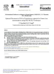
In which, Ti is duration of ith load level (h/year). Also, MP is the energy market price in ith load level ($/MWh) and nt is the number of load levels (load levels may be light, average and heavy, for example).In this paper, load duration curve can be modeled as Fig 1.
1.8
Load factor
2. PROBLEM FORMULATION Simultaneous network reconfiguration and optimal fixed/switched capacitor banks and DG units placement problem can be formulated as an optimization problem. The proposed objective functions include:
1
0.5
0
1000
7760
8760
Time(h)
Fig.1. Load duration curve 2.1.2. Annual cost of purchased active power from upstream network ( IC N )
The impact of DG unit's installations on annual cost of purchased active power from upstream network can be calculated as follows: nt
IC N MP . (PDi PDGi ).T i
(4)
i 1
In which, PDi and PDGi are the total demand and total produced power by DG units in ith load level, respectively. 2.1.3. Annual costs of equipment installation
The equivalent annual cost of equipment installation (fixed/switched capacitor banks and DG units) in distribution system is calculated as: ICd ICC ICDG (5) In
which, IC C and IC DG
fixed/switched respectively.
capacitor
are
annual
banks
and
costs DG
of
units,
2.1.3.1. Annual costs of fixed/switched capacitor banks in distribution system
The equivalent annual costs of fixed/switched capacitor banks installation in distribution system is calculated as: nc f
nca
j 1
j 1
ICC Kcf . Cf j Kca . Ca j nbusC 1000
(6)
In which, the constant Kcf and Kca represent the costs of fixed and switched capacitor banks ($/Kvar), respectively. Also, Cf j and Ca j represent the size of fixed and switched capacitor banks (Kvar), respectively. ncf and nca are the numbers of fixed and switched capacitor banks, respectively. The third term of (6) is the fixed cost of capacitor installation. 2.1.3.2. Annual costs of DG units in distribution system
The investment and operation costs of DG units are computed as:
34
Majlesi Journal of Electrical Engineering ndg
Vol. 9, No. 4, December 2015 2.3.4. DG unit's constraint
nt
IC DG (IC j .Pint j OC j . PDG j i .T i ) j 1
(7)
i 1
In which, IC j and
OC j represent the annual costs of
investment and operation of DG units, respectively. Also, Pint j represents the size of jth DG unit installation. Therefore, PDG represents the produced j i power amount by jth DG unit in ith load level. 2.3. Constraints The proposed objective function is accompanying with the equality and inequality constraints. These constraints should be satisfied during the optimization process. 2.3.1. Load Flow Equations
These equations are given by the Kirchhoff’s laws and determine the active and reactive power flows in the network: N (8) P P V V Y cos( ) 0 ; n , i gni
dni
ni
j 1
nj
nj
ni
nj
nj
N
Q gni Qdni V ni V njY nj sin( ni nj nj ) 0 ;
n , i
(9)
j 1
2.3.2. Voltage limits
Voltage limits refer to the requirement for the system bus voltages, to remain within a narrow range of levels. Since voltages are affected primarily by reactive power flows, the marginal cost of reactive power at each bus is directly dependent on the voltage level requirement at that bus. Voltage limits can be expressed by the following constraints:
V nimin V ni V nimax where,
V
min ni and
V
;
n , i
max ni
are
the
(10) minimum
and
maximum voltage levels that are considered 0.95 and 1.05 per unit, respectively. 2.3.3. Line flow limit
The apparent power flow of the distribution network lines is limited by the flow limit of the lines.
S i j S imax j
i 1,..., n
(11)
The active and reactive power flow of the line between bus i and j is computed as: (12) Pi j V iV jY ij cos(i j ij )
Qi j V iV jY ij sin(i j ij ) where,
(13)
S imax j is the maximum flow limit of the lines
limits that can be found in [35].
The used DG source must have the allowable size as the following range: (14) Pdgmin,i Pgni Pdgmax i 1,..., n ,i U dg ,i where,
Pdgmin,i and Pdgmax ,i are the minimum and
maximum limits of DG units that are considered 0.0 and 100 Kw for one DG, respectively. Also, U dg ,i is an integer variable that can vary from 0 to 15. Therefore, the maximum capacity of DG units is 1.5 MW. 2.3.5. Capacitor banks constraint
The maximum capacity of capacitor banks constraints is formulated as QCn QC max U Cn ; n 1,..., N . (15) where,
QC max is the maximum capacity of one fixed
capacitor bank that is considered to be 300 Kvar in this work. Also, U Cn is an integer variable that can vary from 0 to 5. Therefore, the maximum capacity of fixed capacitor banks is 1.5 Mvar. Also, the discrete capacitor sizes values and related costs considered in this paper and [36] are the same. 3. PROPOSED METHODOLOGY In this paper, a dedicated GA is used to solve the optimization problem of simultaneous reconfiguration and allocation of DG units and fixed/switched capacitor banks in distribution systems. Additional information of dedicated GA can be found in [36]. Briefly, GA has been increasingly applied to the solution of electrical engineering problems because of its efficiency and relative simplicity of implementation. However, the success of a GA relies on an efficient coding of the solution process and on the correct application of the genetic operators (crossover and mutation). The conventional GA use a chromosome composed by binary numbers and the crossing among the chromosomes allow the change of the genetic material, preserving the population diversity. The mutation operator acts directly on chromosome, changing the value of one of their genes in a way to provide an additional form of population diversity. However, the conventional GA cannot be directly applied to solve the reconfiguration problem since the mutation and crossover operators, applied to the chromosome that represents a certain configuration, may not retain the radial structure of the system. In this work, a dedicated GA was used, taking advantage of the particular characteristics of distribution systems. The method avoids the generation of non-radial configurations. The initial population is obtained by a heuristic branch exchange algorithm (for the reconfiguration) that uses a
35
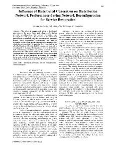
Majlesi Journal of Electrical Engineering sensitivity index based on minimum current in the loop. For the capacitor and DG placement process, an index based on active and reactive load allocations and voltage levels is used. The sensitivity index significantly reduces the search space, reducing also the computational burden. The flowchart of the dedicated GA proposed to solve the problem is illustrated in Fig. 2, where CH represents the set of tie-switches in the first part of the chromosome, Cf represents the fixed capacitor allocation, Ca represents the switched capacitor allocation and P represents the DGs allocation and POPIN represents the current population. The stop criteria adopted in this paper interrupts the iterative process after a certain number of generations. Start Read network data
Generate initial population
Tournament Selection Crossover (CH, Cf, Ca, P)
t=t+1
Mutation(CH, Cf, Ca, P) Fitness Calculation Replace worst individuals of POPION
N
Convergenc e Y Print the best configuration founded
Fig. 2. Flowchart of the used GA 4. SIMULATION RESULTS The proposed method for simultaneous network reconfiguration and allocation of DG units and fixed/switched capacitor banks has been implemented to standard distribution test system with 69 buses. Line and load data for 69-bus distribution system can be found in [35]. The considered objective function
36
Vol. 9, No. 4, December 2015 encompasses the total cost of power loss, the investment and operation costs of DG units, the installation cost of fixed/switched capacitor banks and cost of purchased active power demand from upstream network. The obtained simulation results and comparison of different scenarios shows that the simultaneous network reconfiguration and allocation of DG units and fixed/switched capacitor banks results in significant advantages such as power loss reduction, with good voltage profile improvement and increasing voltage stability index in distribution system. As mentioned previously, distribution network reconfiguration, DG placement and capacitor placement are implemented independently. In this section, different scenarios are considered for the sequence of the implementation. Scenario1: first capacitor placement-second DGs placement-third reconfiguration Scenario2: first DGs placement-second capacitor placement-third reconfiguration Scenario3: first reconfiguration-second capacitor placement-third DGs placement Scenario4: first reconfiguration-second DGs placement-third capacitor placement Scenario5: simultaneous reconfiguration-capacitor placement-DGs placement The coefficient of investment cost of capacitor banks and DG units are shown in Table 1. Table 1. Coefficient of investment cost of capacitor banks and DG units MP Kcf Kca ICDG OC ($/Kwh) ($/Kvar) ($/Kvar) ($/Mw.yr) ($/Kwh) 0.06 3 4 150000 0.045 4.1. Simulation results of scenario1 In this scenario, first fixed/switched capacitor placement, then DGs placement and finally network reconfiguration is done, respectively. The obtained simulation results for Scenario1 are shown in Table 2. Table 2 includes objective function value; optimal site and size of fixed/switched capacitor banks, DG units, and switches that should be open. Table 2. Results of Scenario1 Objective 2,116,500.45 function ($/yr) Reconfiguration 10 – 13 – 44 – 56 - 64 (open switch) size of each 300 Kvar capacitor banks Optimal site Optimal size Fixed capacitor (bus) (number capacitor banks) 21 1 (300 Kvar) 61 2 (600 Kvar)
Majlesi Journal of Electrical Engineering
Switch capacitor
Optimal site (bus) 61
DG units
Optimal Site: 62
Vol. 9, No. 4, December 2015
Optimal size (number capacitor banks) 0-2-4
DG installation size (Kw)
900
4.1.2. Simulation results of Scenario2
In this scenario simulation, first DG placement, then fixed/switched capacitor placement and finally network reconfiguration is done, respectively. The obtained simulation results for this scenario are shown in Table 3. This table includes objective value, optimal site and size of DG units and fixed/switched capacitor banks, and switches that should be open. Table 3. Results of Scenario2 Objective function 2,122,762.00 ($/yr) Reconfiguration 10 – 13 – 44 – 57 - 73 (open switch) Size of each 300 Kvar capacitor Optimal site Optimal size Fixed capacitor (bus) (number capacitor banks) 21 1 (300 Kvar) 60 1 (300 Kvar) 61 1 (300 Kvar) Optimal site Optimal size Switch capacitor (bus) (number capacitor banks) Optima l Site: 61
DG installatio n size (Kw)
60 0
Optima l Site: 62
DG installatio n size (Kw)
800
4.1.3. Simulation results of Scenario3
In this scenario, first network reconfiguration, then fixed/switched capacitor placement and finally DGs placement is done, respectively. The obtained simulation results for Scenario 3 are shown in Table 4. The objective value; switches that should be open, optimal site and size of fixed/switched capacitor banks and DG units are presented in this table.
Table 4. Results of Scenario3 Objective 2,118,064.92 function ($/yr) Reconfiguration 14 – 55 – 61 – 69 - 70 (open switch) size of each 300 Kvar capacitor Optimal Optimal size Fixed capacitor site (bus) (number capacitor banks) 12 1 (300 Kvar) 61 3 (900 Kvar) 65 1 (300 Kvar) Optimal Optimal size Switch capacitor site (bus) (number capacitor banks) -
DG units
Optimal Site: 61
DG installation size (Kw)
700
4.1.4. Simulation results of Scenario4
The order of the planning in this scenario is first network reconfiguration then DGs placement and finally fixed/switched capacitor placement. The obtained objective value; switches that should be open, optimal site and size of DG units and fixed/switched capacitor banks are shown in Table 5.
Table 5. Results of Scenario4 Objective 2,115,361.05 function ($/yr) Reconfiguration 14 – 55 – 61 – 69 - 70 (open switch) Size of each 300 Kvar capacitor Optimal Optimal size Fixed capacitor site (bus) (number capacitor banks) 61 3 (900 Kvar) 64 1 (300 Kvar) Optimal Optimal size Switched site (bus) (number capacitor capacitor banks) -
DG units
Optimal Site: 61
DG installation size (Kw)
800
37
Majlesi Journal of Electrical Engineering
Vol. 9, No. 4, December 2015
4.1.5. Simulation results of Scenario5
In this scenario, simultaneous network reconfiguration and optimal DG units placement and fixed/switched capacitor placement is done. The obtained objective value; switches that should be open, optimal site and size of DG units and fixed/switched capacitor banks are shown in Table 6. Table 6. Results of scenario5 Objective 2,113,308.69 function ($/yr) Reconfiguration 18 – 57 – 64 – 65 - 70 (open switch) size of each 300 Kvar capacitor Optimal Optimal size Fixed capacitor site (bus) (number capacitor banks) 11 1 (300 Kvar) 50 1 (300 Kvar) 60 1 (300 Kvar) 62 2 (600 Kvar)
2.124
Switch capacitor
64 65 Optimal site (bus) -
DG units
Optimal Site: 61
1 (300 Kvar) 1 (300 Kvar) Optimal size (number capacitor banks) DG installation size (Kw)
600
4.1.6. Comparison of different scenarios
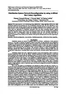
Comparison of different scenarios for objective function value is shown in Fig. 3. The obtained simulation results and comparison of different scenarios confirms that the simultaneous network reconfiguration and allocation of DG units and fixed/switched capacitor banks results in significant advantages.
2.122762
2.122
Cost (M$)
2.12 2.118
2.11806492 2.11650045
2.11536105
2.116
2.11330869
2.114 2.112 2.11 2.108 Scenario 1
Scenario 2
Scenario 3
Scenario 4
Scenario 5
Fig. 3. Comparison of the objective function value for different scenarios The comparison of different scenarios for loss in three load level is shown in Table 7. Table 7 shows the minimum loss in heavy level is in Scenario2, but according to Fig. 3 the required cost for loss reduction in this scenario is higher than other scenarios. Also, annual losses for different scenarios are shown in Fig. 4. Therefore, the voltage profiles for different scenarios in three load level (light, average and heavy) are shown in Figs. 5-7, respectively.
38
5. CONCLUSION In this paper, an efficient joint strategy for reconfiguration, DG placement and capacitor bank allocation in distribution systems is proposed. A dedicated GA intended to minimize the objective function was implemented and tested. Special crossover and mutation, besides a specialized way of forming the initial population, reducing the space search, while allowing good configuration are found. Significant real power loss reduction and cost savings are obtained which leads to reducing significantly the cost of acquisition of capacitor banks and DG units.
Majlesi Journal of Electrical Engineering
Vol. 9, No. 4, December 2015
450
412.11763
403.97376
413.60318
Scenario 3
Scenario 3
Scenario 3
Anuual losses (Mwh)
400 350
327.73881
300 237.07829
250
200 150 100 50 0 Scenario 1
Scenario 2
Fig. 4. Comparison of the annual losses for different scenarios
Table 7. Comparison of losses in different scenarios in three load level Scenario1 Scenario2 Scenario3 Scenario4 3.78 12.55 11.28 9.58 26.86 13.89 32.90 31.18 155.92 130.65 178.47 183.59
Light level Average level Heavy level
Load level = average
Load level = light
1
1.02
0.98
1
voltage profile
voltage profile
1.01
0.99 0.98 0.97 0.96 0.95 0
Scenario5 9.22 32.53 184.47
state 1 state 2 state 3 state 4 state 5 base state 10
20
0.96 0.94 0.92
30 40 bus number
50
60
70
Fig. 5. Voltage profile for different scenarios in light load level
0.9 0
state 1 state 2 state 3 state 4 state 5 base state 10
20
30 40 bus number
50
60
70
Fig. 6. Voltage profile for different scenarios in average load level
39
Majlesi Journal of Electrical Engineering
Vol. 9, No. 4, December 2015
Load level = heavy 0.98
voltage profile
0.96 0.94 0.92 0.9 0.88 0.86 0.84 0.82 0
state 1 state 2 state 3 state 4 state 5 base state 10
20
30 40 bus number
50
60
70
Fig. 7. Voltage profile for different scenarios in heavy load level Also, the proposed approach is able to find good quality configurations as well as to determine the optimal site and size of DG units and fixed/switched capacitor banks in distribution systems, simultaneously. To validate the suitability of the proposed method, it has been applied to 69-bus distribution system. The obtained simulation results and comparison of different scenarios reveals that the simultaneous network reconfiguration, allocation of DG units and fixed/switched capacitor banks results in significant advantages in distribution system.
REFERENCES [1] Su, C. T., Lee, C. S., “Feeder reconfiguration and capacitor setting for loss reduction of distribution systems”, Electric Power Systems Research, Vol. 58, pp. 97-102, 2001. [2] de Oliveira, L. W., Carneiro Jr, S., de Oliveira, E. J., Pereira, J. L. R., Silva Jr, I. C., and Costa, J. S., “Optimal reconfiguration and capacitor allocation in radial distribution systems for energy losses minimization”, International Journal of Electrical Power & Energy Systems, Vol. 32, pp. 840-848, 2010. [3] Chang, C. F., “Reconfiguration and capacitor placement for loss reduction of distribution systems by ant colony search algorithm”, IEEE Transactions on Power Systems, Vol. 23, pp. 17471755, 2008. [4] Farahani, V., Vahidi, B., Abyaneh, H. A., “Reconfiguration and capacitor placement simultaneously for energy loss reduction based on an improved reconfiguration method”, IEEE Transactions on Power Systems, Vol. 27, pp. 587595, 2012. [5] Rong, Z., Xiyuan, P., Jinliang, H., Xinfu, S., “Reconfiguration and capacitor placement for loss reduction of distribution system”, in IEEE Region 10 Conference on Computers, Communications, Control and Power Engineering, 2002, pp. 1945-1949.
40
[6] Kalantar, M., Dashti, R., “Combination of network reconfiguration and capacitor placement for loss reduction in distribution system with based genetic algorithm”, in 41st International Universities Power Engineering Conference, 2006, pp. 308-312. [7] Kasaei, M. J., Gandomkar, M, “Loss Reduction in Distribution Network Using Simultaneous Capacitor Placement and Reconfiguration with Ant Colony Algorithm”, in Asia-Pacific Power and Energy Engineering Conference (APPEEC), 2010, pp. 1-4. [8] Rezaei, P., Vakilian, M., “Distribution system efficiency improvement by reconfiguration and capacitor placement using a modified particle swarm optimization algorithm”, in IEEE Electric Power and Energy Conference (EPEC), 2010, pp. 1-6. [9] Guimaraes, M. A. N., Castro, C. A., “An efficient method for distribution systems reconfiguration and capacitor placement using a Chu-Beasley based genetic algorithm”, in IEEE Trondheim PowerTech, 2011, pp. 1-7. [10] Rezaei, P., Vakilian, M., Hajipour, E., “Reconfiguration and capacitor placement in radial distribution systems for loss reduction and reliability enhancement”, in 16th international conference on Intelligent system application to power systems (ISAP), 2011 pp. 1-6. [11] Montoya, D. P., Ramirez, J. M., “Reconfiguration and optimal capacitor placement for losses reduction”, in Sixth IEEE/PES Transmission and Distribution: Latin America Conference and Exposition (T&D-LA), 2012 pp. 1-6. [12] Ramli, R. E., Awad, M., Jabr, R. A., “Ordinal optimization for optimal Capacitor Placement and network reconfiguration in radial distribution networks”, in IEEE International Conference on Systems, Man, and Cybernetics (SMC), 2012 pp. 1712-1717. [13] Khalil, T. M., Gorpinich, A. V., and Elbanna, G. M., “Combination of capacitor placement and reconfiguration for loss reduction in distribution systems using selective PSO”, in 22nd International Conference and Exhibition on Electricity Distribution (CIRED), 2013, pp. 1-4. [14] Esmaeilian, H. R., Fadaeinedjad, R., “Optimal reconfiguration and capacitor allocation in unbalanced distribution network considering power quality issues”, in 22nd International Conference and Exhibition on Electricity Distribution (CIRED), 2013. [15] Franco, J. F., Rider, M. J., Lavorato, M., Romero, R. n., “A mixed-integer LP model for the reconfiguration of radial electric distribution systems considering distributed generation”, Electric Power Systems Research, Vol. 97, pp. 5160, 2013. [16] Rosseti, G. J. S., de Oliveira, E. J., de Oliveira, L. W., Silva Jr, I. C., and Peres, W., “Optimal allocation of distributed generation with reconfiguration in electric distribution systems”,
Majlesi Journal of Electrical Engineering
[17]
[18]
[19]
[20]
[21]
[22]
[23]
[24]
[25]
[26]
Electric Power Systems Research, Vol. 103, pp. 178-183, 2013. Zidan, A., Shaaban, M. F., El-Saadany, E. F., “Long-term multi-objective distribution network planning by DG allocation and feeders' reconfiguration”, Electric Power Systems Research, Vol. 105, pp. 95-104, 2013. Rao, R., Ravindra, K., Satish, K., Narasimham, S. V. L., “Power loss minimization in distribution system using network reconfiguration in the presence of distributed generation”, IEEE Transactions on Power Systems, Vol. 28, pp. 317325, 2013. Mirazimi, S. J., Nematollahi, M., Ashourian, M. H., Mirahmadi, S., “Reconfiguration and DG placement considering critical system condition”, in IEEE 7th International Power Engineering and Optimization Conference (PEOCO), 2013 pp. 676-679. Pavani, P., Singh, S. N., “Reconfiguration of radial distribution networks with distributed generation for reliability improvement and loss minimization”, in IEEE Power and Energy Society General Meeting (PES), 2013, pp. 1-5. Mohapatra, A., Behera, S., Nayak, S., Panigrahi, B. K., “A Study on DG and Capacitor Placement in Radial Distribution System. 2012 IEEE International Conference on Power Electronics”, Drives and Energy Systems December16-19, 2012, Bengaluru, India. Valipour, K., Dehghan, E., Shariatkhah, M. H., “Optimal placement of Capacitor Banks and Distributed Generation for Losses Reduction and Voltage THD Improvement in Distribution Networks Based on BBO Algorithm”, International Research Journal of Applied and Basic Sciences. Vol, 4, No. 7, pp. 1663-1670, 2013. Haghdar, K., Shayanfar, H. A., “Optimal Placement and Sizing of DG and Capacitor for the Loss Reduction via Methods of Generalized Pattern Search and Genetic Algorithm”, Power and Energy Engineering Conference (APPEEC), 2010 Asia-Pacific. Heydari, M., Hosseini, S. M., Gholamian, S. A., “Optimal Placement and Sizing of Capacitor and Distributed Generation with Harmonic and Resonance Considerations Using Discrete Particle Swarm Optimization”, International Journal of Intelligent Systems and Applications, 2013, Vol. 7, pp. 42-49. Movahed-Poor, M., Boyerahmadi, S., “Placement of Distributed Generation Unit and Capacitor Allocation in Distribution Networks In Order To Reduce Losses and Develop Voltage Profile Using Genetic Algorithm”, Journal of Basic and Applied Scientific Research, 2012, Vol. 2, No. 12, pp. 12714-12721. Molaei-Ardakani, M. H., Zarei Mahmud Abadi, M., Zabihi Mahmud Abadi, M. H., khodadadi, A., “Distributed Generation and Capacitor Banks Placement in Order to Achieve the Optimal Real
Vol. 9, No. 4, December 2015
[27]
[28]
[29]
[30]
[31]
[32]
[33]
[34]
[35]
[36]
Power losses using GA”, International Journal of Computer Science And Technology, Vol. 2, Issue 4, Oct . Dec. 2011. Baghipour, R., Hosseini, S. M., “Placement of DG and Capacitor for Loss Reduction, Reliability and Voltage Improvement in Distribution Networks Using BPSO”, International Journal of Intelligent Systems and Applications, 2012, Vol. 12, pp. 57-64. Zou, K., Agalgaonkar, A. P., Muttaqi, K. M., Perera, S., “Voltage Support by Distributed Generation Units and Shunt Capacitors in Distribution Systems”, Power and Energy Society General Meeting, 2009. PES '09. IEEE . Sadighmanesh, A., Zare, K., Sabahi, M., “Distributed Generation unit and Capacitor Placement for Loss, Voltage profile and ATC Optimization”, International Journal of Electrical and Computer Engineering (IJECE), Vol. 2, No. 6, December 2012, pp. 774-780. Sadighmanesh, A., Zare, K., Sabahi, M., “Distributed Generation unit and Capacitor Placement for Multi-objective Optimization”, International Journal of Electrical and Computer Engineering (IJECE), Vol. 2, No. 5, October 2012, pp. 615-620. Taher, S. A., Hasani, M., Karimian, A., “A novel method for optimal capacitor placement and sizing in distribution systems with nonlinear loads and DG using GA”, Commun Nonlinear Sci Numer Simulat, Vol. 16, pp. 851–862, 2011. Sajjadi, S. M., Haghifam, M. R., Salehi, J., “Simultaneous placement of distributed generation and capacitors in distribution networks considering voltage stability index”, International Journal of Electrical Power and Energy Systems, Vol. 46, pp. 366–375, 2013. Naik, S. G., Khatod, D. K., Sharma, M. P., “Optimal allocation of combined DG and capacitor for real power loss minimization in distribution networks”, International Journal of Electrical Power and Energy Systems, Vol. 53, pp. 967–973, 2013. Moradi, M. H., Zeinalzadeh, A., Mohammadi, Y., Abedini, M., “An efficient hybrid method for solving the optimal sitting and sizing problem of DG and shunt capacitor banks simultaneously based on imperialist competitive algorithm and genetic algorithm”, International Journal of Electrical Power and Energy Systems, Vol. 54, pp. 101–111, 2014. Baran, M. E., Wu, F. F., “Optimal capacitor placement on radial distribution systems”, IEEE Transactions on Power Delivery, Vol. 4, pp. 725734, 1989. Guimaraes, M. A. N., Castro, C. A., Romero, R., “Distribution systems operation optimisation through reconfiguration and capacitor allocation by a dedicated genetic algorithm”, IET Generation, Transmission & Distribution, Vol. 4, pp. 1213-1222, 2010.
41