International Journal of Physical Sciences Vol. 4 (12), pp. 846-852, December, 2009 Available online at http://www.academicjournals.org/ijps ISSN 1992 - 1950 © 2009 Academic Journals
Full Length Research Paper
Simultaneous sensor and hand-sensor calibration of a robot-based measurement system Aiguo Li*, Defeng Wu, Zi Ma and Huipu Xu Automation Research Center, Dalian Maritime University, Dalian City, China. Accepted 25 November 2009
This paper presents a system for object digitalization by use of a laser stripe triangulation displacement sensor and an industrial MOTOMAN robot. In order to ensure the precision of the scanning system, a novel calibration scheme referred to as one-stage approach is proposed. This procedure mainly utilizes a circular-marked board as calibration target and calibrates the range finder and hand-sensor model simultaneously using the same reference points to eliminate the influences of the range finder calibration error on the hand-eye calibration. Finally, some experimental results are reported and analyzed. Key words: Hand-to-sensor calibration, laser-stripe vision sensor, 3D surface digitalization. INTRODUCTION Performing fast and accurate measurements perhaps become an acknowledged tendency of the mechanical industry nowadays. The most accurate contact system is a CMM with a touch-trigger probe with an accuracy of under 1 m, based on a serial or parallel mechanism. However, better-performance CMMs are large and heavy and therefore not capable of performing fast measurements in the assembly lines. Touch-trigger probes also slow down the measurements, because information is read one point at a time. One way to enhance existing automated manufacturing processes is to integrate an automated measuring system to the production line. Automatic measuring instruments are especially helpful for total inspection aiming selective assembly. If compared to conventional techniques, automatic measurement can be quickly accomplished and is free from human operator influence. A straightforward manner to develop an automated instrument is to use an industrial robot as a base to construct a so-called robot-based measurement system (Ma et al., 2008; Jure et al., 2009). A robot-based measurement system is an integrated device that enables a flexible, robot-based, non-contact, dimension- measuring for in-process use on any assembly line, especially where rapid inspections at numerous,
*Corresponding author. E-mail:
[email protected].
.
difficult to access points are required. It indicates an intrinsic capability to configure measurement quickly for different part geometries and dynamic situations. In order to execute the measuring tasks, it is usually necessary for a ROMS’ user to handle the following three calibrations in advance: sensor calibration, hand–eye calibration and robot calibration. In this paper, we address the first two problems, assuming the third, that is, robot calibration, has been done. The range finders mounted to the robot hand, based on triangulation principle, are combination of one or more cameras and a laser-plane projector. For the calibration of laser-stripe range finders, most existing methods are based on static and manual calibration. During the calibration, the finder is usually placed at a fixed location. The calibration target needs to be placed at several accurately known or measured positions in front of the sensor (Huynh, 1997; Sansoni et al., 2000). Hand–eye calibration is the process of computing the relative 3-D position and orientation of the robot-mounted sensor with respect to the robot hand. A number of approaches have been proposed in the previous literature for hand-eye calibration. The usual way to describe the hand-eye calibration is by means of homogeneous transformation matrices AX=XB (Shiu, 1989; Tsai et al., 1989; Wang, 1992) or AX=ZB (Zhuang, et al., 1994; Dornaika, 1998). A user of a robot-based measuring system may start by
Aiguo et al.
847
surement is completed, the robot controller sends joint encoder readings to the PC and the sensor controller sends the measurements to the PC. Then the robot moves to next position. This pattern continues until the whole measurement task is done. laser-stripe ranger finder
Figure 1. Hardware setup.
calibrating the range finder, followed by calibrating the hand-eye model. After all system components are individually calibrated, the coordinates of an object in the robot base coordinate system can be determined. Such a multistage approach has pros and cons. Since system calibration is performed by calibrating its components or subsystems separately, each component calibration task is relatively simple. The drawback of the multi-stage approach is the parameter estimation errors in early stages propagate to the later stages. In this paper, a onestage procedure is developed for the simultaneous calibration of the range finder and hand-eye relationship. Therefore propagation errors that exist in multi-stage approaches are naturally eliminated. To avoid using external measuring devices and manual operations in the range finder calibration, an automatic method without using any special measuring device is proposed. For hand-eye calibration, Kronecker product and stack operator are adopted to solve AX=ZB to find rotations and translations simultaneously. The remainder of the paper is organized as follows: In section 2, a description for system configuration and calibration model is first given. In section 3, the method for simultaneous calibration of the range finder and hand-eye relationship is stated. In section 4, experimental results of real environment are presented to demonstrate the capabilities of the calibration technique. Finally, some conclusions are given to summarize the study. System setup and Mathematical model A robot-based measurement system described here consists of an industrial manipulator HP3 manufactured by Yaskawa and a laser-stripe range finder developed in our laboratory. The major hardware parts are shown in Figure 1.The measurement flow is as follows: the manipulator moves to one position and its controller sends a signal to request the sensor start measurement. After the mea-
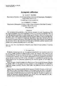
The active range finders are combination of a camera and a laser projector. The laser projector emits a laser plane which is then reflected by the object surface to be observed by a CCD camera. The calibration model, which includes the camera and projector models, describes the perspective projection from the 3D camera coordinates to the 2D image plane coordinates. Assume T Pw = [xw, yw, zw,] to be a point in the world coordinate system {W} and it has coordinates in the camera T coordinate system{C} expressed by Pc = [xc, yc, zc] . It is a rigid body transformation from Pw to Pc, which can be expressed by (1)
P c = R Pw + t
(R,t), called the extrinsic parameters, is the rotation and translation which relates the world coordinate system to the camera coordinate system. Let Pn be the projection of Pc onto the normalized image plane, which is parallel to the image plane and has unit distance to the lens center. Then, Pn can be given by
xn
Pn =
=
yn
xc zc yc zc
(2)
Considering the influences of the radial distortion, we have the distorted projection Pd on the normalized image plane expressed by
xd = Pn + kr 2 Pn yd
Pd =
(3)
r 2 = x n2 + y n2 and k is the lens distortion
Where;
coefficient. Then the projection on the physical image plane Pi can be expressed as follows:
Pi =
u v
=
f u xd + u 0 f v y d + v0
(4)
Where fu and fv are the horizontal and vertical focal lengths, respectively and u0 and v0 are the coordinates of
848
Int. J. Phys. Sci.
xw ow
P( x w , y w , z w )
Normalized image plane
pect to robot base frame can be represented by
zc
T = A1 A2
zw
oc
xc
yc
θ i = θ iEncoder − θ 0i
Camera frame
the principle point. We express the parametric equation of the laser plane in the camera coordinate system as (5)
Then the coordinates xc, yc, and zc of a scene P in the camera reference frame can be determined by its image coordinates u and v (Figure 2).
The MOTOMAN HP3 robot with 6DOF (degrees of freedom) is mainly used for automation of assembly in industrial processes. The HP3 features a 701 mm horizontal reach and a 0.033 mm repeatability specification. The HP3 robot was used as a carrier for the laser-stripe range finder for acquisition of the X, Y and Z coordinates. HP3 robot consists of a sequence of links connected together by actuated joints. The kinematical relationship between any two successive actuated joints is defined by the D-H (Denavit-Hartenberg) homogeneous transformation matrix. The D-H homogeneous transformation matrix is dependent on the four link parameters, that is, θi, αi, ri and di. Described by the D-H definition, the homogeneous transformation matrix Ai which relates the (i-1)th joint to ith joint is given by
Ai =
A laser range finder is mounted in the front of a robot hand for digitizing object surface. Denote the rigid transformation from the range finder coordinate system to the robot hand coordinate system to be H, which is fixed but yet unknown. Assume the homogeneous coordinate T vector of a point to be xc = [xc, yc, zc, 1] and xh= [xh, yh, T zh, 1] , which are corresponding to the sensor coordinate system and the robot hand coordinate system respectively. The range data, which are obtained in the sensor coordinate system, can be transformed to those in the robot hand coordinate system using the following equation.
x h = Hx c
MOTOMAN HP3 robot
cosθi − sinθi cosαi
sinθi sinαi
ai cosθi
sinθi
cosθi cosαi
− cosθi sinαi
ai sinθi
0 0
sin ai 0
cosai 0
di 1
(8)
Hand-sensor transformation
Figure 2. Camera model.
axc + by c + cz c + 1 = 0
(7)
Notice that 0i defines the relationship between the encoder physical reference mark position of each joint and the initial position considered in the definition of the kinematic model. Thus, the joint variable i used in the measuring model is related to the rotation reading provided by the encoder through the following equation.
Pn ( x n , y n ) Pd ( x d , y d ) O X Y
y w World frame
AN −1 AN
(6)
The D-H parameters of HP3 are listed in the Table 1 and the position and orientation of robot hand frame with res-
(9)
Suppose the robot hand frame and robot base frame to be separated by homogeneous matrix T, then the sensor’s data can be expressed in robot base coordinate system as
x b = THx c
(10)
Equation 9 is named as finder-robot model, which relates the range finder coordinate system to the robot base coordinate system. The hand–eye calibration is to determine the transformation matrix H. Simultaneous calibration of range finders and handeye transformation The range finder calibration is separated into two sequenced procedures: camera calibration and projector calibration. During the projector calibration, the calibration target is fixed and the camera observes a planar pattern from different views. At every robot hand position, the laser-stripe is projected onto the target and a least square method is utilized to find a straight line that best fits laser-stripe points. After extracting the laser stripe in ith image through least square technique, a point Pj of the
Aiguo et al.
849
Table 1. Nominal parameters of HP3.
Frame No. A1 A2 A3 A4 A5 A6
0i/deg
i/deg
0 90 0 0 -180 -180
-90 180 -90 90 90 180
laser stripe image can be transformed into the normalized image plane by the following equation.
x nj
−1
fu
0
u0
y nj = 0
fv
v0
v
1
0
1
1
0
u (11)
xc = x nj t l j : y c = y nj t zc = t
(12)
(1) Calculating homography between the calibration target plane and its image. T The relationship between a 3D point Pw [xw, yw, 0,] on T the planar pattern and its image projection m = [u; v] is given by
~ ~ = HM sm
(13)
~
~ and M are the Where s is an arbitrary scale factor; m homogeneous coordinate vector of m and Pw respectively. H is estimated through maximum likelihood criterion. (2) Determining the extrinsic parameters for each image h1
(14a)
r2 = A h 2 r3 = r1 × r2
(14b)
A
−1
−1
t = A h3 .
fu
0
u0
0 0
fv 0
v0 1
and is previously determined by Tsai method (Tsai 1987). Vector hi (I = 1, 2, 3) is the ith column of the matrix H. Once the extrinsic parameters are obtained, the equation of calibration plane in the camera frame is acquired as:
ai xc + bi y c + ci z c + 1 = 0
Note that the extrinsic parameters Ri and ti relate the world coordinate system {W} to the camera coordinate system{C}, they are determined by the following procedures and more detailed information refers to Zhang’s research (Zhang, 2000).
r1 =
di/mm 0 0 0 -380 0 -90
Where; A is given by
A=
Since Pj locates at the beeline passing through optical center and point (xnj, ynj, 1), it gives
−1
ai/mm 100 370 85 0 0 0
(15)
From (12) and (15), the intersection of beeline lj and pi can be determined by
xcj = − x nj (a i x nj + bi y nj + ci ) y cj = − y nj (a i x nj + bi y nj + ci ) z cj = − 1 (a i x nj + bi y nj + ci )
(16)
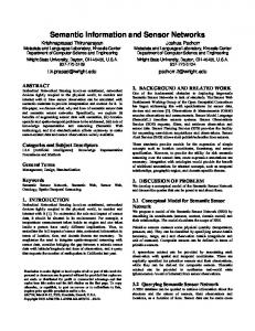
Consequently, the intersection line of the laser plane and the calibration plane has been found for ith image from a T number of points (xcj, ycj, zcj) . We can obtain m beelines located in the laser plane from m images. Therefore, the equation of the laser plane in the camera coordinate system can be obtained from m images. As to hand-eye calibration, the derivation of AX=ZB is illustrated in Figure 3. The world frame {W} relative to the robot base Frame{R} is denoted by Z. Similarly, the range finder frame {S} relative to robot hand frame, the world frame relative to the range finder frame and the robot hand frame relative to robot base frame are denoted by X, A and C, respectively. Then we have
Z = AXC -1
(17) -1
Multiply C in both sides and let B = C , it gives
(14c)
AX = BZ
(14d)
Definition 1: The stack operator maps an n by m matrix
(18)
850
Int. J. Phys. Sci.
Figure 3 Robot/world (Z) and hand/eye (X) calibration. Figure 4 Image of circularmarked board.
into an nm by 1 vector. The stack of the n by m matrix A, denoted vec(A), is the vector formed by stacking the columns of A into an nm by 1 vector.
vec( A) = [a11 , a12 ,
, a1n ,
a mn ]Τ
Definition 2: The Kronecker product is a binary matrix operator that maps two arbitrarily dimensioned matrices into a larger matrix with special block structure. Given the n by m matrix A and the p by q matrix B, their Kronecker product, denoted A ⊗ B , is the np by mq matrix with the block structure
a11 B
a1n B
a m1 B
a mn B
[ ]
Extend the equation AX=ZB, we have (19)
R At X + t A = RZ t B + t Z
(20)
Using stack operator in (19) and (20), it gives
[I
3
(R ) ] vec vec(R ) X
=0
(21)
Z
⊗t
Τ B
− RA
I3
]
vec( R X ) tX tZ
= tA
is a 3 by 3 vec ( R X ) = x and vec ( R Z ) = z , simplified as
RA ⊗ I 3 − I 3 ⊗ RBΤ 0
I3 ⊗ t
Τ B
0
0
identity matrix, let (15) and (16) are
x z
− RA I 3 t X tZ
=
0 tA
(23)
EXPERIMENTS AND DISCUSSIONS
R A R X = R B RZ
Τ A ⊗ I 3 − I3 ⊗ RB
I3
The solutions to x, z, tx and tz can be determined by least square technique. The rotation part Rx and Rz constructed by x and z may not be an orthogonal matrix due to noise and a Rodrigues’ rotation formula is utilized to make Rx and Rz orthogonal.
A ⊗ B = aij B =
[R
Where;
(22)
A circular-marked board is adopted as calibration target because their centroids can be easily extracted by gravity method (shown in Figure 4). The origin of the planar coordinate system {W} coincides with the left-upper corner. Since the relative positions of all the corner mark with respect to the origin are known, this board can provide a set of coplanar reference points. Our experiments utilize a 768 × 576 CCD camera, a laser plane projector and an industrial robot as shown in Figure 1. The robot moves to five different positions and five images are obtained for calibration. Generally speaking, the more image data obtained, the more accurate calibration result is. It is found that driving the robot to five different positions is sufficient. Table 2 shows the calibrated system parameters and the rotation part is described by Rodrigues parameters. Figure 5 shows the re-projection error of the reference points into the camera
Aiguo et al.
Table 2. Calibration results.
fu fv u0 v 0 k
Ri
ti
Hand eye
Laser plane
1271.65,1322.52 346.14,262.60 0.0002 [-0.1015 0.4112 0.0156] [ 0.0389 -0.1642 0.1958] [ -0.0968 0.1158 0.0208] [ 0.1858 0.0695 0.0117] [-0.0927 -0.1626 0.0252] [ 73.526 40.398 88.209] [ 69.688 43.366 89.406] [-18.935 68.767 96.140] [-1.562 -20.648 116.864] [-39.613 88.416 -68.141] RX : [-0.3087 0.2362 3.0369] tX : [29.19 5.37 62.64] RZ : [-0.0058 2.2076 2.1746] tZ: [1164.22 31.64 62.84] 0.6290xc0.0492yc+0.7759zc+79.8728=0
Figure 5. Re-projection projector (in pixel).
error
of
the
the camera image and projector image planes using the calibration results. The re-projection error of the projector is 0.1364 ± 0.0849 pixels. To demonstrate the robot-based measurement system performance, a ball was measured. The ball diameter was firstly measured using a high precision 3D coordinate machine. The precision of the 3D coordinate machine is 0.001 mm. The measurement result is 44.8614 mm. Using our measurement system, the diameter of the ball was measured six times. The results are 44.9414, 44.9227, 44.7862, 44.9367, 44.3355, 44.9528 and 44.9378 mm. Compared with the standard value, there is about ± 0.1 mm error. From the measurement results acquired from the reference ball, it can be concluded that the dimensional
851
error between the CMM contact approach and the approach is relatively higher. One source is the robot positioning error. Although robot joint resolver measurements are highly precise and lead to excellent positional repeatability for consistent loading conditions, this high repeatability does not guarantee accurate positioning performance. Related studies (Roth, 1987) have drawn the conclusion that almost eighty-five percentage of positioning error is related to the inaccuracy of robot kinematic model. Other errors come from laser stripe range finder. Curless (1995) has described how, in optical triangulation systems, the accuracy of the range data depends on the proper interpretation of the light reflections imaged. Sensors based on the triangulation principle can give irregular measurements if the laser beam hits the edge of the object or if a reflectance discontinuity is present on the surface of the object. The future study consequently should be focused on improving accuracy by calibrating the robot. CONCLUSIONS A system for non-contact dimensional measurement using a laser range finder and an industrial robot has been developed. Our efforts concentrate on two key factors in a robot-based measurement system: laser-stripe range finder and hand-eye calibration. The proposed method enables the range finder and hand-eye calibration to be accomplished simultaneously using the same reference points. The preliminary experimental results show that the calibration approach is stable, accurate and can be applied to the robot-based measurement system. Although the simultaneous sensor and hand-sensor calibration has been designed and works well, it should be recognized that this only solves the partial calibration problems in the robot-based measurement system. The robot kinematic calibration plays an important role on the measurement accuracy and must be paid more attention. Future work will be focused on improving the measurement accuracy by compensating the robot positioning error.
REFERENCES Curless B, Levoy M (1995). Better optical triangulation through space time analysis. In Proceedings of international conference on computer vision, Cambridge, MA, USA pp. 987–94. Dornaika F (1998). Simultaneous Robot-World and hand-Eye Calibration. IEEE Transaction on Robotics and Automation, 4 (14): 617-622. Huynh DQ (1997). Calibration of a structured light system: a projective approach. In Proceedings IEEE Conference on Computer Vision and Pattern Recognition pp. 225–230. Jure R, Justin I, Marko M (2009). Dimensional measurements of a grayiron object using a robot and a laser displacement sensor. 8 Ma Z, Xu H, Hu Y (2008). A Novel Robot Surface Measurement System Enhanced with 3D Surface Reconstruction. Int. J. Modeling, Identification Control 4(3): 288- 298.
852
Int. J. Phys. Sci.
Roth Z, Mooring B, Ravani R (1987). An overview of robot calibration. IEEE J. Robot. Autom. 3(5): 377-385 Sansoni G, Carocci M, Rodella R (2000).Calibration and performance evaluation of a 3-D imaging sensor based on the projection of structured light. IEEE Trans. Instrum. Meas. 49(3): 628–636 Shiu YC, Ahmad S (1989). Calibration of wrist mounted robotic sensors by solving homogeneous transform equations of the form AX = XB. IEEE Trans. Robot. Autom. 5(1): 16-27. Tsai RY (1987). A versatile camera calibration technique for high accuracy 3D machine vision metrology using off-shelf TV camera and lenses. IEEE J. Autom. 3(4): 323-334. Tsai RY, Lenz RK (1989). A new technique for fully autonomous and efficient 3-D robotics hand/eye calibration. IEEE Trans. Robot. Autom. 5(3): 345–358.
Wang CC (1992). Extrinsic calibration of a robot sensor mounted on a robot. IEEE Trans. Robot. Autom. 8(4):161–175. Zhang Z (2000). A flexible new technique for camera calibration. IEEE Trans. Pattern Anal. Mach. Intel. 22(11): 1330-1334. Zhuang H, Roth Z, Sudhakar R (1994). Simultaneous robot/world and tool/flange calibration by solving homogeneous transformation of the form AX = YB. IEEE Trans. Robot. Autom. 4(10): 549–554.