SINE AND COSINE GENERATOR USING CORDIC ALGORITHM IMPLEMENTED IN ASIC M.SRIRAM DEPATMENT OF SENSE VIT UNIVERSITY, VELLORE ,INDIA
[email protected]
CHANDRA BIHARI DEPARTMENT OF SENSE Vit University Vellore,India.
Abstract-: Objective of this paper is to generate sine and cosine function using CORDIC algorithm.CORDIC comes fast when to evaluate DSP algorithms uses basic function such as addition, multiplication, trigonometric functions etc. This algorithm uses simple addition, subtraction and shift operation in place of multiplication, it is a hardware efficient algorithm. Here the inputs are vector coordinate and desired angle of rotation. The results show that sine and cosine values of the outputs. The flow of this paper starts with RTL simulation using IES, synthesis using RTL Compiler and finally physical design using SoC Encounter. Keywords-:CORDIC, sine,cosine
I.INTRODUCTION CORDIC(Coordinate Rotation Digital Computer) was first proposed by Jack.E.Volder and further works on this was extended by John Walther[1]. This uses givens rotations transform for trigonometric functions. To design the hardware efficient Digital Signal Processing algorithm, CORDIC algorithm is the best solution[4]. It works on the principle of rotating the given vector coordinate with a constant angle till the angles become zero. This algorithm eliminate the multiplication operation into the simple shift, addition or subtraction operation. Software solutions[2] are available to solve the basic functions such as multiplication, trigonometric, inverse trigonometric functions etc. is by using LUT(look up table) and expansion of polynomial which is used in multiplication, addition and subtraction operations. CORDIC technique is used in scientific calculator applications[5]. Many types of CORDIC architecture available having its own advantage and disadvantages. Among them serial architecture [6]is simplest having three adder or subtractor and two shifter with LUT(Look up table). It is a area specific architecture. Serial architecture having
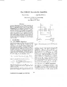
disadvantages of slow speed because, it execute each output after n clock cycle.Pipelined architecture based on cascaded connection of CORDIC blocks. It uses fixed shift register at every stsge of pipelined. Pipelined is better than the serial architecture as it performs faster operation and absence of look up table[3],[6].In existing system they implemented in FPGA platform to calculate sine and cosine function. In this paper we are implementing in ASIC platform using IES(Incisive Enterprise Simulator)to simulate the algorithm, for synthesis we are using RTL Compiler and SoC Encounter used for physical Design. Below fig.I shows the input vector Xin and Yin, while Xout and Youtare the outputs cosine and sine value of inputs after rotating through the angle Ө.
Xin Yin θ
CORDIC ALGORITHM
Xout Yout
Fig.I : Block Diagram
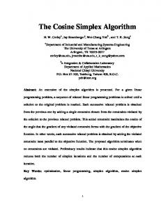
II.CORDIC ALGORITHM The objective of this algorithm is to calculate sine and cosine value of given angle of rotation said theta(Ө).A point in 2-D space can be represented as a vector.Consider a point in a circle shown in the fig.II
(cosθ,sinθ)
θ
-X
gain. Rotation mode having a gain An, approximate to 1.647. This gain depends upon number of iteration occurs.
(1,0)
An=∏√1+2-2i LUT convert angular system to required system. For more specific operation we required additional adder and subtractor to accumulate post iteration of rotation angle.
-Y
Zi+1=Zi– di.tan-1(2-i) Fig.II:Ө rotation of a point in unit circle Ө rotation of the input point having the co–ordinate of (cosӨ,sinӨ). From this we are able to find the coordinate of any point on x-axis after rotating the given angle Ө.We can represent the equations related to output to input is given by Xout=Xin.cosθ –Yin.sinθ
(1)
Yout=Yin.cosθ +Xin.sinθ
(2)
CORDIC is an iterative technique based on two operations: •
Rotation mode
•
Vector mode
Rotation mode: In this mode the angle of rotation and vector coordinate of a point was given and the coordinate of the input after rotation was calculated. The rotation depends on sign of residual angle, to reduce the value of the residual angle. Xi+1=Xi-Yi.di.2-i
By rearranging the equation for further calculation:
Yi+1=Yi-Xi.di.2-i
Xout=cosθ[Xin-Yintanθ] Yout=cosθ[Yin+Xintanθ] We are restricting the angle of rotation such that tan(Ө)=±2-i and tangent term multiplication is reduced to simple shifter operation.Let i will be the rotation at each iteration and for direction of rotation determined by taking angle to rotate or not, due to the value of cosӨ becomes constant as (cosӨ=cos(-Ө)) . Now the equation becomes
Zi+1=Zi– di.tan-1(2-i) Where, di holds -1 if Zi