2782
IEEE TRANSACTIONS ON NUCLEAR SCIENCE, VOL. 60, NO. 4, AUGUST 2013
Single-Event Performance and Layout Optimization of Flip-Flops in a 28-nm Bulk Technology K. Lilja, Member, IEEE, M. Bounasser, S.-J. Wen, R. Wong, J. Holst, N. Gaspard, S. Jagannathan, D. Loveless, and B. Bhuva, Senior Member, IEEE
Abstract—Alpha, neutron, and heavy-ion single-event measurements were performed on both high-performance and hardened flip-flop designs in a 28-nm bulk CMOS technology. The experimental results agree very well with simulation predictions and confirm that event error rates can be reduced dramatically using effective layout design. Index Terms—Dual-interlocked cell (DICE), Layout design through Error Aware Positioning (LEAP), radhard design methodology, radiation hardening, radiation hardening by design, single-event effect, single-event upsets (SEU), soft error.
I. INTRODUCTION
I
N ADVANCED bulk CMOS technologies, the extreme node proximities lead to a strong charge sharing between several circuit nodes during a single event [1], [2]. This makes the single event a more complex process than in older technologies, where primarily only one circuit node was affected by the single event. It causes new and sometimes unexpected single-event behaviors, and introduces a much stronger dependence of the single-event sensitivity to the layout. Hardened designs based on spatial redundancy are particularly vulnerable to the increased node proximities in advanced technologies. The single-event sensitivity of these types of circuits can be improved by identifying and separating critical nodes in the layout [3], [4]. However, the area penalty associated with mere node separation becomes prohibitive in today’s technologies. If the separation is accompanied by an interleaving of circuit cells, e.g., as proposed by Knudsen and Clark [4], the area penalty may be reduced, but the complexity in routing interleaved cells, and the associated speed nd power penalty limits the applicability of this approach. The Layout design through Error Aware Positioning (LEAP) layout methodology [5], [6] takes a different approach to dealing with the increased charge sharing. The LEAP method rearranges the transistor layout in order to minimize the effects of a single event on the overall circuit response, i.e., this Manuscript received September 28, 2012; revised December 14, 2012; accepted January 14, 2013. Date of publication August 06, 2013; date of current version August 14, 2013. This work was supported by the Defense Threat Reduction Agency under contract HDTRA1-10-C-0078. K. Lilja and M. Bounasser are with Robust Chip Inc., Pleasanton, CA 94588 USA (e-mail:
[email protected]). S.-J. Wen, R. Wong, and J. Holst are with Cisco Systems, San Jose, CA 95134 USA. N. Gaspard, S. Jagannathan, D. Loveless, and B. Bhuva are with the Institute of Space and Defense Electronics, Vanderbilt University, Nashville, TN 37027 USA. Color versions of one or more of the figures in this paper are available online at http://ieeexplore.ieee.org Digital Object Identifier 10.1109/TNS.2013.2273437
approach is not concerned with separation of critical nodes, but rather with placing certain contact areas close together, in order to take advantage of the charge sharing. While the LEAP method, when applied to redundant circuits, will not place contact areas of critical nodes next to each other, the hardness of the generated layout will not be dependent on the distance between critical nodes, but rather on which nodes that are placed next to them. The LEAP method uses layout changes only (no changes in the circuit schematic), resulting in minimal penalties in area, speed, and power performance. This paper details the application of this special layout methodology for the development of radiation hardened flip-flop (FF) designs. The layout optimization involved analysis, design, and simulation with the software package Accuro. Both a high speed D-flip-flop (DFF), for high-performance terrestrial applications, and hardened flip-flops using the DICE circuit [7], for space and defense applications, are included. The flip-flop layouts were implemented and fabricated in a 28-nm bulk CMOS technology from TSMC. The fabricated test integrated circuits (ICs), containing both pre- and postmitigation designs, were tested using -particles, neutrons and heavy ions. The optimized flip-flop layouts showed dramatically reduced error rates, without any significant performance penalties, The rest of the paper is organized as follows: Section II discusses the test IC designs. The test chip and measurement conditions are discussed in Section III. In Section IV the measurement results are presented and compared to predicted simulation results, and error rate predictions for the various flipflops in a space environment are given. The analysis techniques, simulation, and error rate prediction methods are discussed in Section V, and the LEAP methodology and the design of the FFs in Section VI. II. TEST IC DESIGN Four flip-flops with optimized layouts and three reference flip-flops with traditional layout design have been implemented. The optimization involved layout changes only. All cells were implemented with a 12-track cell height using three metal layers M1–M3 for the intracell routing. The test chip implementation used the Circuit for Radiation Effects Self-Test (CREST) circuit [8] with chains of 8184 flip-flops. All support circuits for input to shift register and on-chip error detection were designed using a TMR approach. A. High-Performance Flip-Flops While single-event performance has become an increasingly important reliability issue for terrestrial applications, high-performance designs will only be hardened if the penalties in
0018-9499 © 2013 IEEE
LILJA et al.: SINGLE-EVENT PERFORMANCE AND LAYOUT OPTIMIZATION OF FLIP-FLOPS
2783
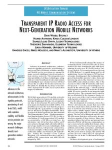
Fig. 1. Simulations data in 40 nm for the base-line DFF (option0, blue) and the optimized DFF (option 5, red). The figure shows the average cross-section between blanket 0 and blanket 1 data patterns at normal incidence.
power, speed, and area (as well as other performance parameters) of the mitigation methods are minimal. It is, therefore, highly desirable to find logic cell designs which mitigate single-event effects without affecting power consumption or speed of operation. Using a method that only modifies the layout, the penalties in speed and power can be kept minimal (some penalty due to differences in cell routing may result, but it can be kept very small). Furthermore, the DFF layout optimization was accomplished with a small area increase of about 10–15%. The starting point for the soft error optimization of a high-performance flip-flop was a D-flip-flop (DFF) implemented in a 40-nm technology and characterized w.r.t. single-event performance [9], [10]. This DFF served as the base-line (option 0) for the single-event layout optimization. The layout for the base-line DFF was first optimized w.r.t. single-event behavior at the 40 nm node using the methodology mentioned above (and discussed further in Section IV). The optimization was accompanied by a thorough characterization using single-event simulation. Several layout options were implemented and analyzed using the simulation tool Accuro. The simulated original base-line DFF (option 0) and the optimized DFF (option 5) cross-sections in the 40-nm technology are shown in Fig. 1. The optimized DFF has exactly the same netlist as the base-line, minimal power or speed penalties, but a 15% larger area. Based on these simulation results for the 40-nm technology node, designs for the target technology node were developed. Both the base-line and the optimized layout DFFs were then implemented in a 28-nm bulk technology. The two 28-nm DFFs were analyzed using simulation and implemented on the singleevent test chip. B. Hardened Flip-Flops By introducing redundancy in the circuit, flip flops designs can be created which are hard against a single event affecting one circuit node only. Many such designs are based on the DualInterlocked Cell (DICE) FF [7]. Results from 32- and 40-nm technology platforms have shown that DICE FF designs with traditional layouts are
Fig. 2. DICE circuit from [7]. The basic DICE circuit configuration consists of the four storage nodes 1–4 and the eight transistors connected to these nodes.
Fig. 3. SEU rate of a regular unhardened flip-flop versus a traditional DICE flip-flop as a function of the technology node. The [*] data points are the two traditional DICE flip-flops in this work.
showing increased vulnerability to single-event upsets (SEU) [2], [11]. Experimental data for these designs show neutron error rate reductions for DICE compared to non-DICE flip-flops for these bulk technologies ranging from 1.5–5 (Fig. 3). This ratio used to be around 1000, or higher, for older technologies [12]–[14]. Thus, techniques other than just spatial redundancy are needed to regain the advantage of DICE FF designs for deep-sub-micron technology platforms. For evaluation and comparison of the SEU performance of DICE flip-flop designs, five DICE flip-flops were implemented in the 28-nm bulk CMOS technology. The DICE circuits used the basic DICE configuration (Fig. 2) with two inputs (data and clock, no preset or clear) and with three different clocking schemes (A–C). Circuit A is a NAND-based D-latch configuration [2], B used a tristate clocking [12], and C the original sram clocking style [7] also used in [4]. Two of the DICE FF (DICE1 and DICE2) use a traditional layout and three were designed using the LEAP methodology (LEAPDICE1, 2t4C, and 2t26B). The layout design is discussed further in Section VII. All five layouts are dense, i.e., there are no empty regions in the layout or interleaving of layouts from separate flip-flops or from master and slave latch.
2784
IEEE TRANSACTIONS ON NUCLEAR SCIENCE, VOL. 60, NO. 4, AUGUST 2013
TABLE I RELATIVE PERFORMANCE COMPARISON OF THE DICE LEAPDICE FLIP-FLOPS IN 28-nm TECHNOLOGY
AND
TABLE II MEASURED (NORMALIZED) SEU ERROR RATES FOR THE TWO DFFS Fig. 4. Normalized experimental cross-section in 28 nm for DFF option 0 (blue) and DFF option 5 (red). Note that the largest improvement in the option MeVcm mg does not show up in these HI measurement 5 (at data (compare Fig. 1).
TABLE III MEASURED (ABSOLUTE) SEU RATES FOR THE FIVE HARDENED FLIP-FLOPS
at Lawrence Berkeley National Laboratory (LBNL) with the 10-MeV ion cocktail in vacuum. Five different ion species were used; O ( MeVcm mg ), Ne (3.49), Ar (9.74), V (14.59), and Xe (58.78). All experiments were performed at normal incidence at a supply voltage of and a fluence of cm . IV. MEASUREMENT RESULTS AND COMPARISONS TO SIMULATION PREDICTIONS
The relative area, dynamic power, and clock-to-Q delay of the five hardened flip-flops are shown in Table I. DICE2 and LEAPDICE1 have identical circuits, and, by comparing the data for these two FFs in Table I, it is clear that the penalty of using a LEAP layout over a traditional layout is minimal. III. TEST CHIP DESIGN AND MEASUREMENT CONDITIONS All single-event measurements were performed at a frequency of 10 MHz using both blanket 0 and blanket 1 data patterns. Error count was shifted out from the on-chip error counter using a field-programmable gate array to monitor all shift registers in parallel. Neutrons experiments were conducted at the ANITA facility at the Svedberg Laboratory in Sweden. The neutron testing was performed at supply voltages ranging from V to V. Fifteen test ICs were exposed to the neutron beam simultaneously to improve the error statistics. All ICs were monitored continuously for errors. The neutron fluences used for FIT calculations were calibrated to account for differences between boards. The neutron data in Tables II and III below are sums over 6 measurement runs, each at a fluence of about cm for each run. -particle experiments were performed at Vanderbilt University using a 10- Ci Am241 source. The source covered the entire DUT and the source-to-die spacing was less than 3 mm. Blanket 0 and blanket 1 patterns were tested at a supply voltage of V. Heavy-ion experiments were performed
Tables II and III show the measured upset error rates for the two DFFs and the five hardened flip-flops for all radiation exposures. The tables show the average between blanket 0 and blanket 1 data patterns and include data from several measurement sessions, where all flip-flops were measured simultaneously. A. DFF Measurement Results Table II shows the relative upset error rates for the two 28-nm DFF designs. The values in Table II have been normalized to the lowest error count for each radiation type. As discussed above, the simulation results predicted that the layout optimization would provide the largest improvements in single-event behavior at low LET values (Fig. 1), and, as can be seen in Table II, the optimized DFF achieved a factor of 4× lower error rates for the lowest LET values ( -particles). At the highest LET value (58.78 MeVcm mg ) the advantage of the optimized DFF was less pronounced % also well in agreement with simulation predictions. The normalized measured heavy-ion cross section for the original layout and the optimized layout are shown in Fig. 4, and comparisons between the measured data and simulated predictions are shown in Fig. 5. B. Hardened Flip-Flop Measurement Results Table III shows the upset error rates for the five DICE FF designs. The neutron cross-sections for the traditional layout DICE1 ( cm per FF) and traditional layout DICE2 ( cm per FF), are considerably smaller than the neutron cross-section reported in [2] for a DICE FF in 40-nm bulk technology ( cm per FF), which shows that
LILJA et al.: SINGLE-EVENT PERFORMANCE AND LAYOUT OPTIMIZATION OF FLIP-FLOPS
Fig. 5. Normalized experimental data in 28 nm (markers) and simulation (line) for the optimized option5 DFF.
2785
Accurate simulation analysis (Section V) predicts that all the LEAPDICE designs are error free for normal incidence up to an LET of 60 MeVcm mg , which gives further support for the assumption that the errors in the LEAPDICE FFs are caused by SETs. Even though the errors in the LEAPDICE FFs are likely to be caused by SETs it is interesting to make a quantitative comparison between traditional layout and the LEAP layout DICE FFs. Using the measurement with the best statistics, (heavy ions at MeVcm mg ), the ratio between the best traditional design, DICE2, and the weakest LEAP, LEAPDICE1, is 100×. As expected, and predicted by simulation analysis (see Section V), these result indicate that the advantage of the LEAPDICE1 layout versus the traditional DICE2 layout is considerably larger for a 28-nm technology, than in an older 180 nm technology where LEAPDICE1 showed about five times lower error rates than an optimal traditional DICE layout [13] under high-energy proton exposure. V. ANALYSIS TECHNIQUE AND ERROR RATE PREDICTION
Fig. 6. Estimated error rates caused by SETs for the heavy ion experiments (red), and actual error rates for the LEAPDICE flip-flops.
our traditional DICE designs have a very good single-event performance, with DICE2 having an optimal behavior for a traditional layout. The LEAPDICE FFs exhibited very few errors. While the two traditional DICE FFs showed a considerable sensitivity to neutron radiation, all three LEAPDICE FFs were error free for both and neutron radiation. In the heavy-ion measurements the LEAPDICE flip-flops exhibited a few errors. However, these errors were most likely caused by single-event transients (SETs) on the output nodes of an opaque latch being clocked into the following latch. Measurements at different frequencies are planned and will confirm this. However, a rough estimate of the rate of errors caused by such transients can be found by (1) where the SETRate is the number of SET errors, is the number of FFs in the chain (8184), PW is the pulse width of the SET, and Area is the sensitive area for generation of SETs on the output node of an opaque latch. From investigations of combinational logic gates in this technology, it is known that the SET pulses range from 100–600 ps, and the area of the output inverter sensitive region is estimated to be about 0.02–0.2 m . Using these estimates, a total fluence of cm (two measurements at ) and the measurement frequency (10 MHz), the range for the number of SET errors (for the heavy ion measurements) was estimated to be 0.2–10. The lower value (0.2) would be for a low LET particle ( MeVcm mg ) and the high value (10) for a high LET particle ( MeVcm mg ). Fig. 6 shows the estimated error rate caused by SETs along with the errors recorded for the LEAPDICE FFs in the heavy-ion experiment.
During the design phase, the two DFFs, the DICE2, and the LEAPDICE FFs were analyzed and optimized using single-event simulations with the single-event analysis tool suite from RCI.1 This analysis software contains a full 3-D representation of the IC, and applies 3-D transport simulation to describe the charge generation and transport and simulates this self-consistently with the circuit, similar to a mixed-mode device-circuit simulation using Technology CAD (TCAD). However, it applies specialized models for the charge collection and for the coupling to the circuit, which allows the simulations to be much faster than regular 3-D TCAD (which is too slow for this type of analysis). This simulation method also requires less calibration than regular TCAD, since it uses the calibrated compact models (from the PDK) for the internal device characteristics. The main advantage over various types of compact model based (spice-type) single-event circuit simulation, is that the layout is represented and modeled a priori, and the simulation provides a predictive accuracy of the single-event behavior for different layouts and configurations. The simulation is accurate and fast enough to generate a complete representation of the single-event behavior of logic cells and smaller circuits. Such a complete simulation captures the regions in the layouts for which a single event can generate an upset (or another target action) in the circuit, as a function of LET, of the incidence angle of the particle generating the event , and of the circuit state (S). The representation is referred to as a cross-section map, . When the regions in the cross-section map are visualized (as in Figs. 7 and 8) they show the regions where the single event (with the specified conditions) would generate an upset in the circuit (or generate any other target event of choice). Fig. 7 shows eight different maps for three different LET values (4, 16, 60 MeVcm mg ) and three different angles , (90 , 0 ), (90 , 325 ). The maps are for states 0 and 1, corresponding to data 1 and 0 blanket patterns in the master latch. The color coding for the different maps is shown 1The tools Accuro, rExplore, and Roview from Robust Chip Inc., were used for the analysis and design work in this paper. www.robustchip.com
2786
IEEE TRANSACTIONS ON NUCLEAR SCIENCE, VOL. 60, NO. 4, AUGUST 2013
TABLE IV COLOR CODING FOR THE MAPS IN FIG. 7
Fig. 7. Cross-section maps for the traditional DICE2 for states 0 and 1 (blanket patterns, master latch). The figure shows the maps for three different incidence directions, and three different LET values.
Fig. 8. Cross-section map for (90 , 325 ), MeVcm mg , for the traditional DICE2 including a visualization of the traces of the particles that generated the upsets in the map.
TABLE V PREDICTED SEU RATES FOR A SPACE ENVIRONMENT
. The map for radiation coming from the “bottom” is set to zero (while, in reality, it would be symmetric). The above simulation technique was used extensively in the design of the FFs in this work and the agreement between predicted cross-sections and subsequent measurements is very good. A comparison for one of the DFFs was shown above in Fig. 5, and a comparison of the predicted and the measured cross-section for the traditional DICE2 is shown in Fig. 9. In order to predict error rates, and to compare the three different LEAPDICE designs, complete cross-section maps and cross-section functions were generated for the traditional DICE2, and for the three LEAPDICE designs. The error rates for a geostationary orbit (solar min, 400 mils shielding) were then calculated using the folding integral
Fig. 9. Comparison of measured and predicted cross-section for the DICE2 FF. Normal incidence, blanket data patterns 1 and 0.
(2) in the Table IV (the cross-section maps for the non-normal directions in Figs. 8 and 9 have been rotated to the plane of the figure). The direction (90 , 325 ) has the largest cross-section for the DICE layout (see discussion in Section VI). In order to clearly see which areas in the layout that are affected for off-axis directions, the particle traces can be plotted along with the maps. Fig. 8 shows such a plot for the map for (90 , 325 ) and MeVcm mg . The areas of the regions in the cross-section map form the cross-section function, , which is used for the calculations of error rates below. While the cross-section maps provide very good information about where in the layout the upset originates for different angles of the incident particle, it may also be useful to get an overall picture of the cross-section (value) as a function of angle. This can be visualized as a color-coded cross-section in a spherical plot as shown below in Fig. 12 (Section VII). In this figure the color in a particular direction on the sphere corresponds to the cross-section at this angle of incidence. Note that our simulations only included radiation coming from the “top”
where is the differential flux spectrum obtained with CREME96 (in this case the flux is isotropic). The resulting average error rates over the eight different states of the flip-flops are shown in Table V. The predicted error rate for LEAPDICE1 is about 75 times lower than the best traditional design (DICE2), incidentally agreeing with the two orders of magnitude reduction found in the heavy ion measurements at normal incidence. While this error rate prediction involves several approximations and the error bars on the absolute value of the predicted rates are somewhat uncertain, the relative differences between the flip-flops are predicted with a much higher confidence. Table V therefore gives a very good indication of the improvement in single-event hardness of the second-generation LEAPDICE FFs over the first generation. As can be seen in the table the improvement ranges from 2 to 10 . Since the predictive accuracy of the analysis and simulation techniques has been verified for many different applications and for many different technologies ranging from 180 nm to the current 28-nm technology, we can, with some confidence, predict that the hardest second-generation LEAPDICE flip-flops
LILJA et al.: SINGLE-EVENT PERFORMANCE AND LAYOUT OPTIMIZATION OF FLIP-FLOPS
2787
TABLE VI ERROR RATE IMPROVEMENT AND PENALTIES FOR LEAP IN ADVANCED BULK TECHNOLOGIES
OVERVIEW
OF
Fig. 11. Principle layout for the traditional DICE2 master latch. P1-4 are the p-fet drains connected to nodes 1–4 in the basic DICE circuit of Fig. 2, n1–4 the n-fet drains.
Fig. 10. Illustration of the guiding principle for LEAP. If a single event affects the drains of both MOSFETs the current pulse of the two drains will compensate, reducing the overall effect of the single event on the circuit.
will not only restore the three orders of magnitude advantage of DICE FFs versus regular FFs, but provide an even greater advantage. VI. LEAP LAYOUT METHODOLOGY The LEAP design methodology [5], [6] is a specific way to optimize a layout for single-event performance. The technique uses layout rearrangements only and improves the single-event soft error performance for implementations of identical circuits. The LEAP methodology can be applied to both nonredundant circuit and redundant circuit. As pointed out above in Section I, the LEAP method, when applied to redundant circuits such as the DICE, does not rely on node separation, and the generated layouts are dense, without empty space and without interleaving of flip-flops or latches. LEAP is applicable to sequential logic, combinational logic, as well as other applications (e.g., analog). The penalties in area, speed, or power can be kept very small. As seen above for the LEAPDICE implementations in 28-nm technology, there was basically no penalty whatsoever in using this method. Table VI gives an overview of the penalties and error rate improvements of LEAP for logic circuits in an advanced bulk CMOS technology. However, the cell routing can become more complex after the LEAP rearrangements, and the performance penalties depend on how well this, more complex, routing can be handled. As mentioned above, all FFs in this work use three metal layers (M1–M3) for the cell routing, but the LEAP designs use a bit more of M3 to handle the more complex routing. A. Operation of the LEAP Methodology The principle guiding a LEAP-based layout optimization is that a single event that affects two or more nodes will generate current pulses on all affected nodes, and the effects can combine to reduce the overall effect of the single event on the circuit. To illustrate this principle, consider a simple inverter with the principle layout shown in Fig. 10 (left). A single event that hits the drain of the n-type MOSFET will generate a positive current pulse on the output node, q, pulling
Fig. 12. Color-coded cross-section as a function of angle of incidence at MeVcm mg .
the voltage on this node low (red curve in Fig. 10). A single event that hits the drain of the p-type MOSFET will generate a negative current pulse on q pulling its voltage high (blue). If the single event affects the drains of both MOSFETs, the two current pulses will compensate and the overall effect of the single event on the circuit will be reduced (black). The generation of a LEAP layout involves the application of a set of rules which take into account how these combined effect of one single event on several contact areas in the circuit affects the overall circuit behavior, and a placement of the contact areas in the layout so as to minimize the overall effect of the single event on the circuit. Consider the DICE circuit (Fig. 2). This circuit cannot be upset by a single event affecting one single node. If two, or more, nodes are affected, however, the DICE circuit can be upset, and there are very many combinations of node pairs that can generate an upset. One pair of contact areas that would generate an upset in this circuit is the drain of the p-type MOSFET connected to node 1 (p1), and the drain of the n-type MOSFET connected to node 2 (n2). In the traditional DICE2 layout (Fig. 11) the two contact areas in this node pair, and several other node pairs of this type, are aligned in the azimuth direction of 325 /145 , and this is the reason that the cross-section is the largest in this direction (compare Figs. 7 and 12). According the LEAP principle the contact area of these two nodes should not be placed adjacent in the layout. However, in the same way as for the INV above, the two drains connected to node 1, n1 and p1, do have compensating (opposite) effects on the circuit when simultaneously affected by a single event. If contact area n1 is placed between p1 and n2, a single event that affects p1 and n2 will also affect n1, and the current pulse on n1 will compensate the effects on p1 and n2 (w.r.t. the overall behavior of the circuit) and hence reduce the single-event sensitivity. A generic application of LEAP starts by capturing the effects of a single event on a circuit in a so-called LEAP matrix which
2788
IEEE TRANSACTIONS ON NUCLEAR SCIENCE, VOL. 60, NO. 4, AUGUST 2013
quantifies how the effects of one single event on multiple contact areas interact and combine to affect the overall circuit behavior. The contact areas are then placed relative to each other in the layout so as to minimize the effect of the single event on the overall circuit behavior [5], [6]. This process, in the general case, generates several different (advantageous) contact area placements, which then are analyzed with the accurate simulation method discussed above to determine which ones are most advantageous. The DFF option 5 and the LEAPDICE layouts (LEAPDICE1, 2t4c, and 2t26b) on the 28-nm test chip are special (patent pending [5], [6]) layout designs generated using this methodology. Fig. 12 shows the color-coded cross-section for the DFF option 0, the traditional DICE2, and the LEAPDICE1 flip-flops at MeVcm mg . In these figs., the flip-flop layout is oriented with the long side along the direction , as illustrated by the blue rectangle in the figures. Note also that, in these figures, the cross-section for tilt angles larger than 90 has simply been set to zero. The leftmost figure shows the cross-sections for the (non-redundant) DFF. This flip-flop can be upset at any angle of incidence, with maximum cross-section at normal incidence and the smallest cross-section at gracing angle along the long side of the layout . The center figure shows the cross-sections for the traditional DICE2 flip-flop. At MeVcm mg the maximum cross-section for this FF is at , but it has nonzero cross-section at normal incidence (consistent with the measured upset threshold of around 10 MeVcm mg , compare Fig. 10). The right figure show the LEAPDICE1, for which the nonzero cross-section remains in a small angle cone around for all LET values. VII. CONCLUSION In ultra-deep submicron ( 28-nm) technologies the effect of a single event on an electronic circuit depends strongly on the layout of the circuit. The charge sharing between several nodes in the circuit renders the traditional use of redundancy to harden logic circuits ineffective. Using the LEAP layout methodology, however, the negative effects of charge sharing between sensitive nodes can be eliminated. This method, in fact, takes advantage of the charge sharing to reduce the effects of a single event on the circuit. Experimental results in a 28-nm bulk CMOS technology confirm that LEAP designs achieve dramatic reductions in singleevent error rates, without any significant performance penalties. For a standard (nonredundant) flip-flop an error rate reduction of up to 4 was achieved, and for the (redundant) DICE flip-flop the error rate reduction was more than two orders of magnitude. The improvements are achieved by layout changes only and the measurements compared different layouts for the same identical
circuit. Our results show that the new approach of using LEAP layout designs will yield dramatically reduced upsets rates for logic circuits for both terrestrial and space radiation environments. ACKNOWLEDGMENT The authors thank the Taiwan Semiconductor Manufacturing Company for providing the test devices in the context of the Cisco single-event test chip consortium. REFERENCES [1] O. A. Amusan, L. W. Massengill, M. P. Baze, A. L. Sternberg, A. F. Witulski, B. L. Bhuva, and J. D. Black, “Single-event upsets in deep submicrometer technologies due to charge sharing,” IEEE Trans. Device Mater. Reliab., vol. 8, no. 3, pp. 582–589, Sep. 2008. [2] T. D. Loveless, S. Jagannathan, T. Reece, J. Chetia, B. L. Bhuva, M. W. McCurdy, L. W. Massengill, S.-J. Wen, R. Wong, and D. Rennie, “Neutron and proton-induced single-event upsets for D- and DICEflip/flop designs at a 40 nm technology node,” IEEE Trans. Nucl. Sci., vol. 58, no. 3, pp. 1008–1014, Jun. 2011. [3] N. Seifert, P. Slankard, M. Kirsch, B. Narasimham, V. Zia, C. Brookreson, A. Vo, S. Mitra, B. Gill, and J. Maiz, “Radiation-induced soft error rates of advanced CMOS bulk devices,” in Proc. IEEE Intl. Rel. Phys. Symp., 2006, pp. 215–225. [4] J. E. Knudsen and L. T. Clark, “An area and power efficient radiation hardened by design flip-flop,” IEEE Trans. Nucl. Sci., vol. 53, no. 6, pp. 3392–3399, Dec. 2006. [5] Robust Chip Inc., “Layout Method for Soft-Error Hard Electronics, and Radiation Hardened Logic Cell,” USA US12/354,655, 2008, patent pending. [6] Robust Chip Inc., “Soft-Error Hard Electronic Circuit and Layout,” USA US12/763,139, 2009, patent pending. [7] T. Calin, M. Nicolaidis, and R. Velazco, “Upset hardened memory design for submicron CMOS technology,” IEEE Trans. Nucl. Sci., vol. 43, no. 6, pp. 2874–2878, Dec. 1996. [8] P. Marshall, M. Carts, S. Currie, R. Reed, B. Randall, K. Fritz, K. Kennedy, M. Berg, R. Krithivasan, C. Siedleck, R. Ladbury, C. Marshall, J. Cressler, N. Guofu, K. LaBel, and B. Gilbert, “Autonomous bit error rate testing at multi-gbit/s rates implemented in a 5AM SiGe circuit for radiation effects self test (CREST),” IEEE Trans. Nucl. Sci., vol. 52, no. 6, pp. 2446–2454, Dec. 2005. [9] B. Bhuva, B. Narasimham, A. Oates, K. Patterson, N. Tam, M. Vilchis, S. Wen, R. Wong, and Y. Xu, “Soft error testing at advanced technology nodes,” in IEEE Proc. Intl. Reliability Phys. Symp., 2011, pp. 5B.1.1–5B.1.4. [10] S. Jagannathan, T. D. Loveless, Z. Diggins, B. L. Bhuva, S. J. Wen, R. Wong, and L. W. Massengill, “Neutron- and alpha-particle induced soft-error rates for flip flops at a 40 nm technology node,” in IEEE Proc. Intl. Reliability Physics Symp., 2011, pp. SE.5.1–SE.5.5. [11] N. Seifert et al., “On the radiation-induced soft error performance of hardened sequential elements in advanced bulk CMOS technologies,” in IEEE Proc. Intl. Reliability Physics Symp., 2010, pp. 188–197. [12] M. P. Baze, M. P. Baze, B. Hughlock, J. Wert, J. Tostenrude, L. Massengill, O. Amusan, R. Lacoe, K. Lilja, and M. Johnson, “Angular dependence of single-event sensitivity in hardened flip/flop designs,” IEEE Trans. Nucl. Sci., vol. 55, no. 6, pp. 3295–3301, Dec. 2008. [13] K. Lee, K. Lilja, M. Bounasser, P. Relangi, I. R. Linscott, U. Inan, and S. Mitra, “LEAP: Layout design through error-aware transistor positioning for soft-error resilient sequential cell design,” in Proc. IEEE Intl. Rel. Phys. Symp., 2010, pp. 203–412. [14] K. Warren, A. Stenberg, J. Black, R. Weller, R. Reed, M. Mendenhall, R. Schrimpf, and L. Massengill, “Heavy ion testing and single-event upset rate prediction considerations for a DICE flip-flop,” IEEE Trans. Nucl. Sci., vol. 56, no. 6, pp. 3130–3137, Dec. 2009.