946
IEEE TRANSACTIONS ON POWER ELECTRONICS, VOL. 17, NO. 6, NOVEMBER 2002
Single Phase Three-Level Power Factor Correction Circuit With Passive Lossless Snubber Hongyang Wu and Xiangning He, Senior Member, IEEE
Abstract—Multilevel conversion techniques, power factor correction (PFC) techniques and soft switching techniques are the three research hot points of power electronics. The paper proposes a single phase three-level PFC circuit with passive lossless snubbers which embodies these trends. Firstly, the three-level buck and boost topologies are derived from one bridge leg of the traditional diode clamped three-level inverters. Then, a single phase three-level PFC circuit is presented based on the three-level boost topology, and the principle and implementation approaches of the three-level PFC circuit are described. To realize the soft switching of the main switches and freewheeling diodes, two passive lossless snubber cells are added to the circuit. The operating principle and design considerations of the new circuit are discussed in detail. Finally, a 2 KW prototype of the single phase three-level PFC with the passive lossless snubber is built and tested. The simulated and experimental results indicate that the proposed circuit can realize the function of three-level PFC, increase system efficiency and have no over-voltage stresses on main power switches. Moreover, the power factor of the proposed circuit with the passive lossless snubber is higher than that of the circuit without the snubber.
are derived at first. Then the principle and implementation approaches of the three-level PFC circuit constructed by the three-level boost topology are researched. In order to increase the system efficiency and improve the EMI without resulting in the complexity of control, two passive lossless snubber cells without over-voltage stresses are added into the three-level boost circuit and a novel single phase three-level PFC circuit with the passive lossless snubber is attained. The simulations and experimentation have been done with a 2 KW prototype in the laboratory, and the results tested from the proposed circuit are included. Finally the conclusions for this new configuration of the passive soft switching single phase three-level PFC is given.
Index Terms—DC/DC converter, power factor correction, snubbers, soft-switching, three-level converter.
Fig. 1(a) shows one bridge leg of a diode clamp three-level inverter. Just as a two-level inverter bridge leg can be divided into a buck and a boost circuits, one bridge leg of a three-level inverter can also be divided into a three-level buck and a three-level boost circuit topologies as shown in Fig. 1(b) and (c), respectively. The two topologies derived directly from the original three level circuit can not be used in practice because there is a neutral point voltage unbalance problem resulting from the unbalance of charging or discharging of the dc division capacitors. Using the topology of Fig. 1(c) as an example, due to the existence of the diode in the neutral point connection line, the neutral point current can only flow in one direction so that the neutral point voltage becomes uncontrollable. To keep the balance of the neutral point voltage, the neutral point current should be controlled and flow in bi-direction. The other obstacle of applying the topology into practice is that there are nonsensical switch and are connected in state combinations. The switches series in Fig. 1(c), and the switch state combinations of “00,” “10,” and “11” are significant if the on-state and off-state of or are denoted as “1” and “0,” respectively. These combiand are charged by the inductor nations correspond that , is charged by the inductor and inductor discharges itself respectively. But the switch state “01” is meaningless and it can not realize any expected electrical functions. Due to the reasons above, some revisions without resulting in any changes of the basic electrical function are done and the new topologies are shown in Fig. 2. Obviously, the neutral point line current can flow in bidirection and all switching state combinations can complete the expected electrical functions in these topologies. The analysis method above can also be used for the buck circuit shown in Fig. 1(b). The three-level boost topology is analogous
I. INTRODUCTION
W
ITH increase of the requirements for high voltage and high power level power electronic equipment, multilevel converters, as an interesting solution, have drawn tremendous interest recently. Meanwhile, the harmonics and EMI problems caused by using power electronic equipment are more and more serious, thus the power factor correct (PFC) techniques have become another research hot point in the power electronics field. For the reason well known, high switching frequency is always one of the power electronics objects, although accompanying with switching losses increased. To solve the problem, the soft switching techniques are widely applied, which can also improve the EMI of the equipment. This paper finds a proper application object that embodies the above three research hot points, and presents the new configuration which consists of a single phase three-level PFC circuit with passive lossless snubbers. Based on one bridge leg of the traditional diode clamped three-level inverters, the single phase three-level buck and boost topologies with practicality
Manuscript received January 20, 2002; revised May 16, 2002. Recommended by Associate Editor F. Blaabjerg. This work was supported by the National Nature Science Foundation of China (59947006) and the Delta Science and Education Foundation for Power Electronics Research and Development. This paper was presented at the IEEE APEC’2002 Conference, Dallas, TX, March 2002. The authors are with the Power Electronics Research Institute, College of Electrical Engineering, Zhejiang University, Hangzhou 310027, China (e-mail:
[email protected]). Digital Object Identifier 10.1109/TPEL.2002.805578
II. DERIVATION
0885-8993/02$17.00 © 2002 IEEE
OF
SINGLE PHASE THREE-LEVEL PFC TOPOLOGY
WU AND HE: SINGLE PHASE THREE-LEVEL POWER FACTOR CORRECTION CIRCUIT
947
Fig. 3. Control block of three-level PFC circuit.
Fig. 1. Three-level buck, boost topologies derived from three-level inverters.
(dc) when the input voltage is 220 V (ac). If the input voltage increases or a higher output voltage is expected, the output voltage will increase accordingly, which means the power switches should stand a higher voltage stress than 400 V. It will result in, on the one hand, the increase of the switching loss and conducting loss, on the other hand, the difficulty of selecting power switches since the MOSFET with a high rated voltage is of shortage and expensive. This single phase three-level PFC circuit based on the three-level boost topology provides a good solution for a single phase PFC operating under high voltage and high frequency conditions. III. SIMULATION AND EXPERIMENTATION OF SINGLE PHASE THREE-LEVEL PFC SYSTEM
Fig. 2. Three-level buck, boost topologies with practicability.
with the two-level boost ones, so it can also be used as a PFC circuit. In the traditional PFC circuit based on a two-level boost topology, the output voltage is usually controlled at 400 V
In fact, the topology of the three-level PFC and its operational principle were discussed in [1] and [2] before, but they did not give the origin of the topology. The control block of the single phase three-level PFC is shown in Fig. 3, here the logic “ ” is used to judge the operating region and the logic “ ” is used to control the neutral point voltage balance. The logic “ ” is a signal coming from UC3854 with a fixed frequency, so the switching frequency of the gate pulse signal is almost fixed. Contrastively, the “ ” in [2] comes from a hysteresis comparator, the switching frequency of the gate pulse signal is variable, which results in the difficulty in designing a soft switching circuit and output filter. To verify the correctness of the control method proposed above, the simulations and experiments are carried out. Fig. 4 shows the simulated results by Pspice simulation tools. It can be seen that the input current can follow the input voltage, the three-level operation is realized and the voltage stresses on and are the same, which equate to half of switches of the output voltage. It also means that the neutral point voltage is balanced. Based on the simulation results, a prototype of 2 KW single phase three-level PFC circuit is built. The corresponding experimental parameters are given as following: and , IRFP460; Input inductor , 2 mH; Power switches and , HFA25TB60; Output capacitor, Freewheel diodes F; AC input voltage, 220 V; Output voltage , 400 V; and Switching frequency, 40 KHz. Fig. 5 shows the
948
IEEE TRANSACTIONS ON POWER ELECTRONICS, VOL. 17, NO. 6, NOVEMBER 2002
(a)
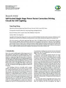
Fig. 6. Topology of three-level PFC with passive lossless snubber.
(b) Fig. 4. Simulation waveforms of three-level PFC. (a) Inpute voltage and current. (b) Voltage V .
experimental results, which is obviously identical with that of the simulation. From the results of the simulation and experiment, an important phenomenon can be observed. On the “shoulders” of the input current of each period, there are two symmetrical distortions, the positions of which just correspond to the instant that the operating region transits from region 1 to region 2 [2]. The phenomenon may be resulted from the hysteresis characteristic of “ ” and slow dynamic response of the current control loop. The power factor of the three-level PFC circuit decreases slightly because of this distortion and the power factor measured is about 0.97. IV. DERIVATION
OF PASSIVE LOSSLESS THREE-LEVEL PFC
SNUBBER
FOR
Although the three-level PFC topology can reduce the voltage stress on switches and diode to a half output voltage, thus reduce the switching loss and on-state loss of the switches and diodes, the total losses are still considerable when the switching frequency is high. It is still necessary and significant to use soft switching techniques to increase the system efficiency. Just as the authors mentioned [3], soft-switching techniques can be divided into two categories, active soft switching techniques and passive soft switching techniques, which have different technical characteristics. In this paper, the latter is applied into the three-level PFC circuit for the sake of simplifying the control. A. Topology and Operation Principle
Fig. 5. Experimental waveforms of three-level PFC. (a) Input voltage and current. (b) Voltage V .
The topology of the single-phase three-level PFC circuit with a passive lossless snubber is shown in Fig. 6 [4]. The added snubber cell, which is one of the simplest passive lossless snubber topologies for the single ended converter circuit, con, a snubber capacitor , sists of a snubber inductor and three diodes , , a buffer capacitor . The resonance among and , realizes the zero current turn-on and zero voltage turn-off of the main power switches as well as zero voltage turn-off and zero voltage turn-on of the freewheel diodes. At the same time, gathers the resonant energy in each switching periods
WU AND HE: SINGLE PHASE THREE-LEVEL POWER FACTOR CORRECTION CIRCUIT
and transfers it into the loads to realize the lossless operation of the snubber circuit. To make it easy to understand the operation principle, the constructed processes and qualitative description of the snubber cell are introduced in brief here. The switches and the freewheeling diodes work in complementary modes in the single ended circuit. In order to realize the zero current turn-on of and zero voltage turn-off of , a snubber inductor must be connected in series in the loop conin Fig. 6. In order to realize sisting of and , such as the zero voltage turn-off of and zero voltage turn-on of , a snubber capacitor must be connected in parallel with or , in Fig. 6. To realize the lossless operation of the cirsuch as cuit, the energy stored in the snubber components must be transferred to the power supply or the load. In practice, the energy is difficult to be transferred directly, so it is stored into a temporary energy-stored component which is usually constructed by a capacitor with large capacitance for the technical feasibility and simplicity. In order to transfer the energy stored in the component into the power supply or load at last, an energy recovery path must be constructed. By the circuit theory, the energy in the circuit can only be transferred from a voltage source to a current source or from a current source to a voltage source, so the energy recovery path for the capacitor must be a current source. In passive lossless snubber circuits, there are only two energy recovery paths that are the main power switches and freewheeling diodes. Thus, the one end of the temporary energy-stored component constructed by a capacitor must be connected with one end of or . As for Fig. 6, if the freewheeling diode is used as the energy recovery path, the energy-stored (buffer) capacitor can be connected in parallel with the freewheeling diode directly. The method makes use of the reverse-blocking characteristics of . During the commutation process, the energy-stored (buffer) cawithin a short time. (The pacitor undertakes the current of time is shorter than the turn-on time of in minimum duty cycle or turn-off time of in maximum duty cycle.) Thus the current source in the – loop can be used as the object of energy recovery. As a result, the position of the energy-stored capacitor and connection method are confirmed in Fig. 6. Some diodes are introduced into the circuit to prevent the interference from the added power source to the operation of main power switches. The proposed passive lossless snubber cell is shown in the region within the dashed block in Fig. 6. In fact, the snubber cell can be applied into any single ended circuit [5]. The proposed snubber cell has no over-voltage stress on the main power switches in principle, because the energy-stored capacitor discharges completely in each period within the normal operation range releasing all stored energy into the load. As a result, the voltage across the capacitor varies between zero and maximum value and thus there is no over-voltage stress on the main power switches. B. Commutation Processes Several assumptions are employed in the following analysis [6]. 1) All devices are ideal except for freewheeling diodes.
949
2) The value of the input inductor is far larger than that of the snubber inductor . 3) The capacitance of the output capacitor is large enough so that the output voltage is constant. Because of the symmetry of the topology, only the commuand is analyzed here. There are tation process between eight commutation stages in each operation period shown in Fig. 7. And the corresponding waveforms are shown in Fig. 8. . Before , is off, and are Stage 1, and conducting on. The circuit is in the stable state of turns on at , the current of decreases the load current. linearly from input current because of the snubber inductor , and at the same time the current of increases from zero. is realized. The current of And the zero current turn-on of is given by (1) . The reverse recovery process of Stage 2, finishes at . After turns off, turns on naturally since and are equal to zero. It begins that the resboth of , snubber capaconant process with the snubber inductor and buffer snubber capacitor connecting in seitor increases from zero by the resonant ries. The voltage across charging process, which realizes the zero voltage turn-off of . The amplitude of the voltage across is equal to . So the current of and can be expressed by (2) (3) where (4)
(5)
(6) is equal to the sum of the input inThe peak current of , which is named , ductor current and the current of and given by and appears when (7) The resonance finishes at turns on
, when
reaches
and
(8) , is charged to and keeps Stage 3, turns on and the second constant at . At the same time, , , and connecting resonant process starts with
950
IEEE TRANSACTIONS ON POWER ELECTRONICS, VOL. 17, NO. 6, NOVEMBER 2002
Fig. 7. Working stages of the proposed three-level PFC with passive lossless snubber.
where (11) (12) (13) is equal to zero at , the second resonance comWhen is transferred to pletes. During the stage, the energy of completely, which is given by
(14) is and the corresponding The peak voltage across is equal to the sum of and voltage stress on Fig. 8. Corresponding waveforms of the proposed three-level PFC with the snubber.
(15) in series. The current of by
and voltage of
can be expressed
(9)
(10)
, decreases to zero and and Stage 4, turn off at . After that, the voltage across and keeps constant respectively. And the circuit is in the stable state that and conduct the input current. , After the switch turns off at , the Stage 5, to through .The voltage input current discharges is equal to , that is to say, the voltage across
WU AND HE: SINGLE PHASE THREE-LEVEL POWER FACTOR CORRECTION CIRCUIT
951
increases from zero according to (16) to realize zero voltage turn-off of (16) : is discharged to zero by the input Stage 6, and . After current at , which results in conducting of is equal to and the voltage of that, the voltage across discharges to by . and are given (17) (18) , At , the current increase to input Stage 7 and turn off. After that, discharges current , and through . increases slowly so that the zero voltage is realized. in this stage is given by turn-on of (19) : At , the voltage of is reduced Stage 8 turns off, as turns on naturally. The energy to zero and is transferred to the load completely. After that, the stored in and the circuit goes back to the load current flows through same stable state as in the stage at waiting for next switching processes. C. Parameter Design and Discussion for Applications Based on the analysis above, several key design points are emphasized as following. of and the losses 1) In order to reduce the turn-on reverse recovery, the value of should be of selected as large enough to meet with special application requirements. and must turn off before is dis2) In stage 6, , and will keep charged to zero. Otherwise, may conducting during the whole switch period, and lose the soft switching condition. So the following inequality must be obeyed (20) is, 3) According to (7) and (15), the larger the value of and the voltage stress the larger the current stress of are. It is obvious that the selection of value of of and should take both 1) and 2) into consideration. is ap4) According to (15), the over-voltage stress on . In order to reduce proximately equal to should be as large the over-voltage stress on , is as possible. If the expected over-voltage stress on , should be equal to 25. During the comturns off with no over-voltage mutation processes, turns on with no over-current stress in principle and in principle.
Fig. 9. Voltage and current waveforms on devices with hard switching. (a) On device S . (b) On device .
D
V. SIMULATION AND EXPERIMENTATION To verify the validity of the proposed passive lossless snubber, a 2 KW prototype of the single-phase three-level PFC circuit with the proposed passive lossless snubber is built. The corresponding experimental parameters are: the snubber H, the snubber capacitor inductor nF, the buffer capacitor F, the diodes , and are MUR8100. Fig. 9 shows the experiand without mental voltage and current waveforms of the snubber. Fig. 10 shows the corresponding experimental waveforms with the proposed snubber. Obviously, the soft and is realized in Fig. 10. Moreover, switching of when it turns off and there is no over-voltage stress on when it turns on, which there is no over-current stress on verifies the analysis above. Fig. 11 shows the input voltage and current waveforms of the three-level PFC circuit with the proposed snubber. Compared with the waveforms in Fig. 5, the waveforms of the soft switching circuit is better than that of the hard ones. The testing value verifies the observed phenomenon. The power factor measured is about 0.99 in the circuit with the proposed snubber, while it is 0.97 in the circuit without the snubber. The reason of the phenomenon is that the limits the changing ratio of the added snubber inductor
952
IEEE TRANSACTIONS ON POWER ELECTRONICS, VOL. 17, NO. 6, NOVEMBER 2002
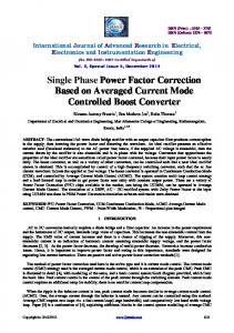
Fig. 12.
Fig. 10. Voltage and current waveforms on devices with the passive lossless . snubber. (a) On device S . (b) On device
D
Efficiency curves of three-level PFC with hard and soft switching.
The three-level buck and boost topologies are derived from the bridge leg of the traditional diode clamped three-level inverters firstly. Two passive lossless snubber cells that require no extra detecting and control circuits are added to the three-level PFC circuit to soften the switching processes of the power switches and freewheeling diodes. Its operating principle and design considerations are discussed in detail. A 2 KW prototype of the single phase three-level PFC circuit with the proposed snubber is built and tested. The simulated and experimental results indicate that the configuration can realize the single phase three-level PFC function, increase the system efficiency and have no over-voltage stresses on main power switches. Moreover, the power factor of the proposed circuit with the passive lossless snubber is higher than that of the circuit without the snubber. REFERENCES [1] M. T. Zhang et al., “Single phase three-level boost power factor corrector converter,” in Proc. IEEE APEC’95 Conf., 1995, pp. 434–439. [2] B.-R. Lin and H.-H. Lu, “Single-phase three-level PWM rectifier,” in Proc. IEEE PEDS’99 Conf., 1999, pp. 63–68. [3] H. Wu, Y. Deng, R. Zhao, and X. He, “A novel passive lossless snubber for multilevel inverters,” in Proc. IEEE APEC’02 Conf., vol. 2, 2002, pp. 1011–1017. [4] X. He, H. Wu, and Y. Deng, “Passive soft-switching three level dc/dc converter,” China Patent, no. 02 110 842.0, 2002. [5] K. M. Smith, Jr. and K. M. Smedley, “Engineering design of lossless passive soft switching method for PWM converters—With minimum voltage stress circuit cells,” in Proc. IEEE, APEC’98 Conf., vol. 2, 1998, pp. 1055–1062. [6] C.-J. Tseng and C.-L. Chen, “Passive lossless snubber for dc/dc converters,” in Proc. IEEE, APEC’98 Conf., vol. 2, 1998, pp. 1049–1054.
Fig. 11. Input voltage and current waveforms of three-level PFC with the passive lossless snubber.
current at the transiting instant from one operation region to the another. And the current distortion is reduced, thus the power factor of the soft-switching three level PFC circuit is increased. Fig. 12 gives the efficiency curves of the three-level PFC circuit with and without the proposed snubber at different loads. VI. CONCLUSION The paper presents a novel configuration of the single-phase three-level PFC topology with the passive lossless snubber.
Hongyang Wu was born in Anhui Province, China, in 1971. He received the B.Sc. degree from Anhui Mechanical and Electrical College, China, the M.Sc. degree from Hufei University of Technology, China, and the Ph.D. degree in power electronics from Zhejiang University, China, in 1993, 1998, and 2002, respectively. From 1993 to 1995, he was an Assistant Engineer with Auhui Iron and Steel Corporation. Currently, he is a Senior Engineer with the Delta Power Electronics Center (DEPC). His research interests include topology, control, and soft-switching techniques of the high power converters.
WU AND HE: SINGLE PHASE THREE-LEVEL POWER FACTOR CORRECTION CIRCUIT
Xiangning He (M’95–SM’96) received the B.Sc. and M.Sc. degrees from Nanjing University of Aeronautical and Astronautical, Nanjing, China, in 1982 and 1985, respectively, and the Ph.D. degree from Zhejiang University, Hangzhou, China, in 1989. From 1985 to 1986, he was an Assistant Engineer at the 608 Institute of Aeronautical Industrial General Company, China. From 1989 to 1991, he was a Lecturer at Zhejiang University. In 1991, he obtained a Fellowship from the Royal Society of London, U.K., and conducted research in the Department of Computing and Electrical Engineering, Heriot-Watt University, Edinburgh, U.K., as a Post-Doctoral Research Fellow for two years. In 1994, he joined Zhejiang University as an Associate Professor. Since 1996, he has been a Full Professor in the Department of Electrical Engineering. He is the Director of the Power Electronics Research Institute, Zhejiang University. His research interests are power electronics and their industrial applications. Dr. He received the 1989 Excellent Ph.D. Graduate Award, the 1995 Elite Prize Excellence Award, and the 1996 Outstanding Young Staff Member Award from Zhejiang University for his teaching and research contributions, two Scientific and Technological Progress Awards from Zhejiang Provincial Government and the State Educational Ministry of China, respectively, and four Excellent Paper Awards. He is a Fellow of the Institution of Electrical Engineers (IEE), U.K.
返
回
953