IEEE TRANSACTIONS ON MICROWAVE THEORY AND TECHNIQUES, VOL. 51, NO. 2, FEBRUARY 2003
593
Single-Substrate Integration Technique of Planar Circuits and Waveguide Filters Dominic Deslandes, Student Member, IEEE, and Ke Wu, Fellow, IEEE
Abstract—The integrated planar technique has been considered as a reliable candidate for low-cost mass production of millimeter-wave circuits and systems. This paper presents new concepts that allow for a complete integration of planar circuits and waveguide filters synthesized on a single substrate by means of metallized post (or via-hole) arrays. Analysis of the synthesized integrated waveguide and design criteria are presented for the post pitch and diameter. A filter design method derived from a synthesis technique using inductive post is presented. An experimental three-pole Chebyshev filter having 1-dB insertion loss and return loss better than 17 dB is demonstrated. Integrating such planar and nonplanar circuits on a substrate can significantly reduce size, weight, and cost, and greatly enhance manufacturing repeatability and reliability. Index Terms—Hybrid integrated circuits, millimeter-wave filters, substrate integrated waveguide.
I. INTRODUCTION
T
HE past decade has witnessed a rapid development of commercial millimeter-wave wireless systems such as local multipoint distribution service (LMDS) and advanced collision-avoidance sensor. Design and manufacturing costs of such systems are probably the most critical issue in the assessment of their commercial vitality. Integration of active and passive components made of the rectangular waveguide generally requires transitions from planar to nonplanar circuits. Various approaches to solving this problem have been proposed that yield some complex mounting structures [1]–[3]. High-precision mechanical adjustment or a subtle tuning mechanism is needed to obtain good performance for mass production. A planar microstrip circuit often needs to be cut into a specific shape, which is hard to realize in the millimeter-wave range. Furthermore, rectangular-waveguide components are voluminous and expensive to manufacture, which inevitably make the planar/nonplanar integration bulky and costly. Recently, the concept of the integrated rectangular waveguide has been proposed [4] in which an “artificial” waveguide is synthesized and constructed with linear arrays of metallized via-holes or posts embedded in the same substrate used for the planar circuit. This waveguide can also be realized with complete metallized walls [5], [7], [8]. Several transitions have been proposed [5]–[8] to excite the waveguide. In all these structures, the planar circuits, such as a microstrip line or coplanar waveManuscript received September 15, 2001; revised May 15, 2002. This work was supported by the Natural Sciences and Engineering Research Council of Canada and by the Canadian Institute for Telecommunications Research. The authors are with the Poly-Grames Research Center, Département de Génie Électrique, École Polytechnique de Montréal, Montréal, QC, Canada H3V 1A2 (e-mail:
[email protected];
[email protected]). Digital Object Identifier 10.1109/TMTT.2002.807820
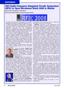
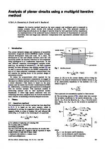
guide, and the rectangular waveguide are built onto the same substrate and the transition is formed with a simple matching geometry between both structures. In order to demonstrate the full potentials of the integrated-waveguide scheme, low-loss passive components should be studied and developed. A number of components using the post-wall waveguide technique combined with a metallic layer were analyzed and simulated previously in [9]. Good results were reported for T-junction and isolation performance between waveguides. However, the realization of a low-loss filter without tuning needs to be demonstrated. Planar filters have already been investigated [10], [11] using the concept of electromagnetic bandgaps (EBGs). However the EBG structure is not necessary to design high- filter and only one row of via with the concept of an equivalent waveguide can be used. This paper presents the design and performance of the integrated-waveguide filter. We begin with a parametric analysis of the synthesized integrated waveguide. Design criteria are presented for the post pitch and diameter in terms of the maximum dimension ratio. A filter design technique is presented with self-consistent inductive posts that are embedded along the waveguide section. It is shown that integrating the two dissimilar structures on a single substrate allows the design of planar circuits and waveguide filter without resort to tuning or usual mechanical mounting. II. INTEGRATED-WAVEGUIDE ANALYSIS Judging from its electrical performance, the synthesized integrated waveguide is a good compromise between the air-filled rectangular waveguide and planar circuit [6]. A schematic view of the integrated waveguide is shown in Fig. 1. This waveguide is composed of two parallel arrays of via-holes, delimiting the wave propagation area, as its cutoff frequency is only related to the width “ ” of the waveguide as long as the substrate thickness or waveguide height “ ” is smaller than “ .” The parameter “ ” between the two arrays determines the propagation constant of the fundamental mode, and parameters of via-holes “ ” and “ ” are set to minimize the radiation loss as well as the return loss. In order to ensure that the synthesized waveguide section becomes radiationless or free from leakage loss, parametric effects of “ ” and “ ” should be studied. A full-wave finiteelement method (FEM) based a commercial software package (HP-HFSS) is used to carry out our simulations.1 Fig. 2 shows the influence of the pitch length “ ” on the loss for diameter mm, “ ” with four posts. The other parameters are mm, and . Since we do not consider the 1Agilent
HFSS ver. 5.6, Agilent Technol. Inc., Palo Alto, CA.
0018-9480/03$17.00 © 2003 IEEE
594
IEEE TRANSACTIONS ON MICROWAVE THEORY AND TECHNIQUES, VOL. 51, NO. 2, FEBRUARY 2003
Fig. 1. Configuration of the on-substrate integrated waveguide synthesized using metallized via-hole arrays.
Fig. 3. Normalized return-loss performance of the integrated waveguide as a function of the normalized via diameter.
Fig. 2. Normalized insertion loss of the integrated waveguide with respect to the pitch length normalized to the wavelength.
dielectric and conductor losses in the simulations, the loss solely comes from the radiation. All the values are normalized by the wavelength in the dielectric material. These curves indicate that the pitch must be kept small to reduce the loss between adjacent posts. However, the post diameter is also subject to is considered the loss problem. As a result, the ratio to be more critical than the pitch length because the post diameter and pitch length are interrelated. For an electrically ), the radiation loss is lower than 0.008 small post ( of 0.5. The loss tends to dB/wavelength with a ratio , decrease as the post gets smaller for a constant ratio which is conditioned by the fabrication process. The synthesized integrated waveguide can no longer be regarded as a normal homogeneous waveguide, and it is, in fact, an artificial periodic waveguide. Therefore, the post diameter may significantly affect the return loss of the waveguide section in view of its input port. Fig. 3 shows the return loss of one period (one via) normalized to the wavelength in relation with the post or via diameter “ ” normalized to the waveguide width “ .” The ratio is kept at 0.5 in the calculations. To obtain good results in terms of the return loss in the waveguide section, the choice of the via diameter must follow such a design . rule as Of course, the above simulations will become inefficient and heavy if a large number of via posts gets involved. To avoid this problem, the synthesized integrated waveguide can simply be modeled by a standard dielectric-filled rectangular waveguide bounded by two parallel metallic walls. To do so,
two integrated waveguides with different lengths are simulated. The phase difference in transmission between the two structures of different lengths allows calculating the propagation constant. This can then be mapped or converted to an equivalent rectangular waveguide with complete bilateral and , the mapping is perwalls. With fect in all the waveguiding bandwidth of interest. Thus, all the existing design procedures and theory developed for the rectangular waveguide are directly applicable to its synthesized counterpart. Nevertheless, dielectric filling effects and geometrical particularity of the synthesized waveguide should be accounted for. III. INDUCTIVE POST-FILTER DESIGN A filter was designed and measured in [7] with metallic walls. This may need high-precision machining, which overcasts the advantage of the synthesized integrated waveguide compared to the rectangular waveguide. To exploit full advantages of the integrated waveguide, a filter is showcased with embedded posts. However, this kind of filter usually requires several posts of different diameter that are normally not available or difficult to realize in the form of conventionally processed via-holes because these via-holes usually have an identical diameter. A general method is now presented to design a filter based on posts of the same diameter. The method starts with the general filter theory. First, the integrated waveguide is mapped to a rectangular waveguide using the technique explained in Section II. As illustrated in Fig. 4(b), a PI network can model a post in rectangular waveguide. The theory developed by Marcuvitz and . [12] for posts in a waveguide is used to calculate This PI network is then transformed into a -inverter using (1) [13]. With this model, filters are designed on the basis of the well-known synthesis techniques for inductive posts in the rectangular waveguide, as described in [13]
(1)
DESLANDES AND WU: SINGLE-SUBSTRATE INTEGRATION TECHNIQUE OF PLANAR CIRCUITS AND WAVEGUIDE FILTERS
595
Fig. 6. Photograph of the manufactured three-pole filter with two microstrip transitions. Fig. 4. Design process of inductive post filter. (a) Post in waveguide. (b) Equivalent PI network. (c) Equivalent -inverter network.
K
(a)
(b) Fig. 5. Topologies of the centered post-filter model with different post diameters and the proposed offset post filter of an identical post diameter. TABLE I DIMENSIONS OF THE CENTERED POST-FILTER MODEL WITH DIFFERENT POST DIAMETER AND THE OFFSET POST FILTER OF IDENTICAL POST DIAMETER DESIGNED WITH 0.77-mm VIA
Fig. 7. Measured and simulated results for the new three-pole Chebyshev filter of offset inductive posts with two transitions of microstrip to integrated waveguide.
Generally, an inductive post filter has to use a number of posts of different diameter all centered in the guide. The filter geometry can be replaced by an offset post arrangement with the same post diameter as illustrated in Fig. 5. To set up the equivalence between the two filter structures, a number of simulations are made to extract the position of equivalent posts in the offset case.
Table I summarizes dimensions of the centered post-filter model, as well as the offset post-filter design with a diameter of 0.775 mm. The manufactured prototype of the filter is shown in Fig. 6 and the HFSS simulated and measured filtering results are shown in Fig. 7. In the passband, the whole insertion loss is 1 dB and the return loss is better than 17 dB, which indicate an excellent performance for this proposed planar approach. The simulated results, based on the rectangular waveguide model, agree well with the measurements. The conductor losses were not modeled in the simulation since the commercial package used is not accurate for small thickness conductor. This explains the difference between simulated and measured results in the passband.
IV. EXPERIMENTAL RESULTS
V. CONCLUSION
With the method presented in Section III, a three-pole Chebyshev filter of 1-GHz bandwidth centered at 28 GHz has been designed, fabricated, and measured. The circuit is constructed on a 0.787-mm-thick dielectric substrate with (RT/Duroid 5880). It has been shown that a factor higher than 500 can be obtained with this substrate [14]. The dimensions of structure referring to Fig. 1 are selected as mm, mm, mm, and the mm. In order to measure the filter, post diameter microstrip transitions are designed as described in [5]. The dimension of the transition, referring to Fig. 1 in [5], are mm, mm, and mm.
New concepts of synthesized waveguide integrated components with planar circuits on a single substrate have been proposed and discussed. Design-oriented analysis of the integrated waveguide has been presented, showing interesting properties. In addition, it is found that a carefully synthesized structure can effectively be replaced by a rectangular waveguide without much difference. Featuring direct integration, small size, and low loss, this new design platform is well suited for a low-cost planar circuit design at millimeter-wave frequencies. To demonstrate the proposed single-substrate hybrid planar/nonplanar technique, a new three-pole filter of 28 GHz with inductive posts has been designed, fabricated,
596
IEEE TRANSACTIONS ON MICROWAVE THEORY AND TECHNIQUES, VOL. 51, NO. 2, FEBRUARY 2003
and measured. The simulated and measured results show that this type of filter can be constructed without tuning. The proposed techniques can be used to integrate passive waveguide components with active microwave integrated circuits (MICs) and monolithic microwave integrated circuits (MMICs) for low-cost mass production without any additional mechanical assembling or tuning. REFERENCES [1] B. N. Das, K. V. S. V. R. Prasad, and K. V. S. Rao, “Excitation of waveguide by stripline and microstrip-line-fed slots,” IEEE Trans. Microwave Theory Tech., vol. MTT-34, pp. 321–327, Mar. 1986. [2] W. Grabherr, B. Huder, and W. Menzel, “Microstrip to waveguide transition compatible with millimeter-wave integrated circuits,” IEEE Trans. Microwave Theory Tech., vol. 42, pp. 1842–1843, Sept. 1994. [3] G. E. Ponchak and R. N. Simons, “New rectangular waveguide to coplanar waveguide transition,” in IEEE MTT-S Int. Microwave Symp. Dig., vol. 1, May 1990, pp. 491–492. [4] J. Hirokawa and M. Ando, “Single-layer feed waveguide consisting of posts for plane TEM wave excitation in parallel plates,” IEEE Trans. Antennas Propagat., vol. 46, pp. 625–630, May 1998. [5] D. Deslandes and K. Wu, “Integrated microstrip and rectangular waveguide in planar form,” IEEE Microwave Wireless Comp. Lett., vol. 11, pp. 68–70, Feb. 2001. , “Integrated transition of coplanar to rectangular waveguides,” in [6] IEEE MTT-S Int. Microwave Symp. Dig., vol. 2, 2001, pp. 619–622. [7] C.-K. C. Tzuang, K.-C. Chen, C.-J. Lee, C.-C. Ho, and H.-S. Wu, “ -plane mode conversion and application in printed microwave integrated circuit,” in Proc. Eur. Microwave Conf., vol. 2, Oct. 2000, pp. 37–40. [8] N. Jain and N. Kinayman, “A novel microstrip mode to waveguide mode transformer and its applications,” in IEEE MTT-S Int. Microwave Symp. Dig., vol. 2, 2001, pp. 623–626. [9] H. Uchimura and T. Takenoshita, “Development of a laminated waveguide,” IEEE Trans. Microwave Theory Tech., vol. 46, pp. 2438–2443, Dec. 1998. [10] W. J. Chappell, M. P. Little, and L. P. B. Katehi, “High isolation, planar filters using EBG substrates,” IEEE Microwave Wireless Comp. Lett., vol. 11, pp. 246–248, June 2001. [11] M. J. Hill, R. W. Ziolkowski, and J. Papapolymerou, “A high- reconfigurable planar EBG cavity resonator,” IEEE Microwave Wireless Comp. Lett., vol. 11, pp. 255–257, June 2001. [12] N. Marcuvitz, Waveguide Handbook, ser. MIT Rad. Lab.. New York: McGraw-Hill, 1951, vol. 10. [13] R. G. L. Matthaei, L. Young, and E. M. T. Jones, “Microwave filters,” in Impedance-Matching Networks and Coupling Structures. New York: McGraw-Hill, 1964. [14] Y. Cassivi, L. Perregrini, K. Wu, and G. Conciauro, “Low-cost and high- millimeter-wave resonator using substrate integrated waveguide technique,” presented at the Eur. Microwave Conf., 2002.
H
Q
Q
Dominic Deslandes (S’01), photograph and biography not available at time of publication.
Ke Wu (M’87–SM’92–F’01) was born in Liyang, Jiangsu Province, China. He received the B.Sc. degree in radio engineering (with distinction) from the Nanjing Institute of Technology (now Southeast University), Nanjing, China, in 1982, and the D.E.A. and Ph.D. degrees in optics, optoelectronics, and microwave engineering (with distinction) from the Institut National Polytechnique de Grenoble (INPG), Grenoble, France, in 1984 and 1987, respectively. He conducted research in the Laboratoire d’Electromagnetisme, Microondes et Optoelectronics (LEMO), Grenoble, France, prior to joining the Department of Electrical and Computer Engineering, University of Victoria, Victoria, BC, Canada. He subsequently joined the Department of Electrical and Computer Engineering, Ecole Polytechnique de Montréal (Faculty of Engineering, University of Montréal) as an Assistant Professor, and is currently a Full Professor and Tier-I Canada Research Chair in Radio-Frequency and Millimeter-Wave Engineering. He has been a Visiting or Guest Professor at Telecom-Paris, Paris, France, and INP-Grenoble, Grenoble, France, the City University of Hong Kong, Hong Kong, the Swiss Federal Institute of Technology (ETH-Zurich), Zurich, Switzerland, the National University of Singapore, Singapore, the University of Ulm, Ulm, Germany, as well as many short-term visiting professorships with other universities. He also holds an honorary visiting professorship at the Southeast University, Nanjing, China, and an honorary professorship at the Nanjing University of Science and Technology, Nanjing, China. He has been the Head of the FCAR Research Group of Quebec on RF and microwave electronics, the Director of the Poly-Grames Research Center, as well as the Founding Director of the newly developed Canadian Facility for Advanced Millimeter-Wave Engineering (FAME). He has authored or coauthored over 320 referred papers, and also several book chapters. His current research interests involve hybrid/monolithic planar and nonplanar integration techniques, active and passive circuits, antenna arrays, advanced field-theory-based computer-aided design (CAD) and modeling techniques, and development of low-cost RF and millimeter-wave transceivers. He is also interested in the modeling and design of microwave photonic circuits and systems. He serves on the Editorial Board of Microwave and Optical Technology Letters. Dr. Wu is a member of the Electromagnetics Academy. He has held many positions in and has served on various international committees, including the vice chairperson of the Technical Program Committee (TPC) for the 1997 Asia–Pacific Microwave Conference, the general co-chair of the 1999 and 2000 SPIE International Symposium on Terahertz and Gigahertz Electronics and Photonics, and the general chair of the 8th International Microwave and Optical Technology Conference (ISMOT’2001). He has served on the Editorial or Review Boards of various technical journals, including the IEEE TRANSACTIONS ON MICROWAVE THEORY AND TECHNIQUES, the IEEE TRANSACTIONS ON ANTENNAS AND PROPAGATION, and the IEEE MICROWAVE AND GUIDED WAVE LETTERS. He served on the 1996 IEEE Admission and Advancement (A&A) Committee, the Steering Committee for the 1997 joint IEEE Antennas and Propagation Society (IEEE AP-S)/URSI International Symposium. He has also served as a TPC member for the IEEE Microwave Theory and Techniques Society (IEEE MTT-S) International Microwave Symposium. He was elected into the Board of Directors of the Canadian Institute for Telecommunication Research (CITR). He served on the Technical Advisory Board of Lumenon Lightwave Technology Inc. He is currently the chair of the joint IEEE chapters of MTT-S/AP-S/LEOS in Montréal, QC, Canada. He was the recipient of a URSI Young Scientist Award, the Institute of Electrical Engineers (IEE), U.K., Oliver Lodge Premium Award, the Asia–Pacific Microwave Prize Award, the University Research Award “Prix Poly 1873 pour l’Excellence en Recherche” presented by the Ecole Polytechnique de Montréal on the occasion of its 125th anniversary, and the Urgel-Archambault Prize (the highest honor) in the field of physical sciences, mathematics, and engineering from the French–Canadian Association for the Advancement of Science (ACFAS). In 2002, he was the first recipient of the IEEE MTT-S Outstanding Young Engineer Award. He was inducted as a Fellow of the Canadian Academy of Engineering (CAE) in 2002.


![Chaos in circuits and systems [Book Review] - Circuits ... - IEEE Xplore](https://m.moam.info/img/260x300/chaos-in-circuits-and-systems-book-review-circuits_5c57ebfc097c479a6e8b45a0.jpg)