Singularity-Consistent Inverse Kinematics of a 6 D.O.F.. Manipulator with a Non-Spherical Wrist. Y. Tsumaki, S. Kotera, D. N. Nenchev and M. Uchiyama.
Proceedings of the 1997 IEEE International Conference on Robotics and Automation Albuquerque, New Mexico - April 1997
Singularity-Consistent Inverse Kinematics of a 6 D.O.F. Manipulator with a Non-Spherical Wrist Y. Tsumaki, S. Kotera, D. N.Nenchev and M. Uchiyama Department of Aeronautics and Space Engineering Faculty of Engineering Tohoku University Aramaki-aza-Aoba, Aoba-ku, Sendai 980-77, Japan Abstract The singulayity-consistent path-planning and motion control approach has been so far successfully tested within a teleoperation environment, but with separate control of the positioning subsystem and the wrist of the slave arm. I n this paper, we show that the approach can be applied to a 6 D.O.F. slave arm with a non-spherical wrist. The problems arising from the coupling between position and orientation are handled easily within the null-space/adjoint Jacobian framework of the singularity-consistent approach. The experiments show that the operator is able to approach the shoulder singularity smoothly, to move through it or to perform motions without leaving it.
1. Introduction The existence of the singularity problem has been recognized for a long time [l],and various approaches have been suggested so far t o handle it. As an example we point out the singularity-robust damped leastsquares method [2], [3]. This method generates a feasible solution around the singularity, however, the endeffector has t o deviate from the commanded velocity. Recently, it has been recognized that control at the singularity is possible without an error in the direction of motion [4]. Some relevant path planning techniques have been proposed since then [5]-[7]. In our previous work we introduced a method for path planning and motion control, called the singularity-consistent (SC) method [8]-[lo]. It is especially useful when teleoperating a slave arm around singularities, but also, it allows for movements through the singularity, resulting in a ”reconfigured” arm. Other motion patterns, such as boundary motion, or self-motion can be also performed at the singularity. The experiments we have done so far included teleoperation of the positioning subsystem and the wrist separately [8], [lo]. Previously, we have pointed out that the approach can be directly applied t o 6 D.O.F. robots with decoupled position/orientation, e.g. having a spherical wrist [lo]. In this paper, we show that the SC method can be also applied to a general 6 D.O.F. arm, without necessarily having a decoupled kinematic structure.
0-7803-3612-7-4/97 $5.00 0 1997 IEEE
2. The Singularity-Consistent Approach Applied to a 6 D.O.F. Arm The inverse kinematics of a nonredundant arm is written as:
where J is the manipulator Jacobian, det J and a d j J denote its determinant and adjoint matrix, respectively, U is an unit vector defined by x = vu. One of the causes of the singularity problem is vanishing of the determinant. Note, that the term (det J ) - l is a scaling factor which is related t o the magnitude of motion in joint space. On the other hand, the term (adjJ ) k determines the relation between the velocities in the individual joints. In order t o overcome some of the difficulties related to the singularity problem, we proposed the following modification of Eq. (1):
where the subscript “r” denoting a reference value, a is the sign variable (a= f l ) and b 2 0 is a scalar variable. With a proper design of c and b we can control a nonredundant arm a t codimension one singularities, and in the vicinity of any singularity, without any error in the direction, and with feasible ,joint velocity. The available freedom in choosing cr and b is apparent if one regards the nonredundant manipulator as a closed system moving on a specified path, such that the velocity and the direction of motion on the path can be selected arbitrarily. In our previous work [lo]; we identified three mot.ion patterns at a kinematic singularity. These are: (1) self-motion, (2) escape/through motion and (3) boundary motion. The self-motion has the same meaning as for kinematically redundant systems: the end-effector velocity is zero while some of the intermittent links are moving. The escape/through motion leaves the singularity. With boundary motion, the end-effector is moving; however, the singularity is
2980
not escaped. The reference end-effector motion direction U , determines which type of motion pattern is t o be generated. The SC approach guarantees that the reference direction of motion u , is maintained precisely, with several exceptions when the shared control mode around a singularity has to be invoked [lo], [12], e.g. t o support the operator when moving through a singularity with so-called Type B velocity relation, or when performing a boundary motion pattern. In the neighborhood of the singularity we modify only the joint velocity magnitude t o stay within a userspecified bound
4
emax:
~lell5 emax-
(3)
This condition will be relevant, if the end-effector velocity is normalized. Note, however, that the norm of the six-dimensional end-effector velocity is not properly defined [13]: it includes components of different dimensions. This necessitates the introduction of a new metric < u , T u u>. We define matrix T uas follows:
T , = ~ vdiag[vmax
,
vmax vmax ~ m a zwmax, wmaz]
(4)
and Wmax denote the end-effector’s maximum velocity and angular velocity, respectively. 77 = f i is used in the general case of mixed translational and rotational command input; 7 = 1 handles the special cases of pure rotation or pure translation. Our experience shows that the operator feels more comfortable with the latter case. Therefore, we shall assume in our further analysis pure rotational or pure translational command input. With the new metric, we have: Vmax
x, = Je
(5)
where
x, = Tux,, J = T uJ . The new metric ensures that the Euclidean vector norm fi,. = ~ ~ ~5 ,1.. ~ l The main result, obtained after the SC approach, is: 6 = cr6 ( a d j J ) & (6) where 6 is determined with reference t o the magnitude D, and the manipulability measure [9].
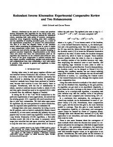
Figure 1. Basic configuration of A-arm decoupled. We note that the case of a spherical wrist, i.e. the case of PUMA-type geometries, is more easily t o handle. First, we derive the determinant of the Jacobian as
+
3 3 where k: = l/(vmaxwmax), 4 = a1 a2c2 + a3c23 - d5S234, C, = cos e,, c,, = COS (e, e,), c , , ~= cos (e, 0, e,), s, = sine,, s,, = sin (e, e,), S , j k = sin (e, 0, &). From Eq. (7), we identify the following three singularities: (1) shoulder singularity ( 4 = 0 ) , (2) elbow singularity (s3 = 0), and (3) wrist singularity (s5 = 0). The elbow singularity will not be addressed here since A-arm cannot be extended fully due t o its hardware joint limits. We note only that the elbow singularity does not need special analysis, and can be directly approached using the following notation. The analysis for the shoulder and wrist singularity follows in the next two subsections, respectively. For comprehensive analysis, we make use of two different representations of the general equation ( 6 ) ,for each of the above two singularities.
+
+ + + +
+
3.1. Shoulder Singularity The shoulder singularity is defined by 4 = 0, in which case the origin of the C5 coordinate frame is located a t the zo axis (see Fig. 2). Using Eq. (6), we derive the SC parameterization of the inverse kinematics in the following explicit form:
e = ab(Hl21l +
3. Singularity-Consistent Inverse Kine-
4212)
matics of A-Arm The 6 D.O.F. arm under consideration is the slave arm of our teleoperation system called ARS/A. Figure 1 shows the kinematic structure of the arm1 and the notation for the kinematic parameters. It is apparent that the wrist axes (the axes of the last three joints) do not intersect at one point. Consequently, the position and the orientation of the end-effector are not
where
Will be referred to therein as “A-arm.”
298 1
U1
=
(9)
3.1.2. U2
Shoulder singularity escape/ through motion The condition for escapefthrough motion is H I = 0 A (F2 # 0 V H2 # 0). In this case, ( a d j j ) U r becomes zero. The cause is the term q5 = 0. This term, however, is a common zero in the numerator and denominator of Eq. (1). Therefore, it is canceled out (cf. the control algorithm below) [lo], [ll],and the resulting equation can be used t o control the motion at the singularity. From Eq. ( 8 ) , we obtain:
=
e2
= u3s3
+ d5c34
(19)
Urt = k u m a x L , i E {x,Y,z } , G-3 = , kwmaxGg j E { a ,P, Y}, U r - [ G x ,u r y , u r z , u r a , u r ~67 ,-711' . Note A
A
^
7
.
that variables denoted by an upper-case letteir include components of vector U , .
el
3.1.1. Shoulder self-motion The condition for self-motion a t the shoulder singularity is: H I = F1 - d6sgG2 # 0. From Eq. (8) we obtain:
e3
e = gbHlvl.
(20)
The above condition is satisfied if either F1 if 0 (this is the case of a translational command), or if G2 # 0, (this is the case of a rotational command). It is especially interesting to note that self-motion can be achieved by either a translational or by a rotational command. In the former case, the translational command comprises components which are normal t o the arm plane, defined by the first three joints. Such a command acts as if the origin of E5 is t o be removed from the arm plane. This, however, never Ihappens; the origin of C5 remains on the .ZO axis, yielding the self-motion. In the latter case, the rotational command comprises some components having a nonzero projection on the y5 axis (G2). Such a command acts in a similar way as the translational one, and the endeffector position and orientation remain constant.
2982
-
L
02
QS5S23G-z
+
=
(22)
a2 s2 3 5 U r z
0
65
06
-
s 5 ( a 3 ~ 2 3 a2s2)firz
e4
-
0
-
a2a3s3G1
-
-
7
a2a3s3Fl
- d5C4F3) - a 3 d 5 d 6 ~ 4 ~ 5 ~ 2 3 4 G ~ - a3H3 - a2H4)$ + d 5 d 6 ~ 5 ~ 2 3 4 e l G 2
a3$(H3
(d5elF3
X Motion patterns generated via a translational command
Motion patterns generated via a rotational command
a2(H4 - e2F3)d' - a Z d 6 C 5 S 2 3 4 e 2 G 2 -a2a3s3(c234Fl - 4G2)
-
-
+a2a3d6s3s234G2
Figure 2. Motion patterns a t the shoulder singularity
as$(& w2
-
d 5 ~ 4 F 3) a3d5d6~4~5~234G2
(d5elF3 - a d 3
=
a2(H4
-
-
(F1 - d6G2s;)a2a333
(-234Fl
+
- a2H4)$ d 5 d 6 ~ 5 ~ 2 3 4 e l G 2 - e2F3)$ - w & c 5 ~ ~ 3 4 e 2 G 2
+ W 2 + d~cz34G2s:')am% +a2a3d6S33234G2
61
1
r
0
1
-
The translational command comprises components which are only within the arm plane (F1 = 0). In this case, the end-effector can translate while keeping the wrist singularity. In the case of a rotational command, G I = 0 A G2 = 0 must hold. The command has only a component along the y4 axis. The end-effector can rotate without escaping the wrist singularity.
4. Implementation and Experiments 4.1. The control a l g o r i t h m Figure 4 shows the flow chart of the control algorithm. u f is the normalized command vector which is generated by means of a forceftorque sensor ball. M and N are constants that determine the vicinity of the shoulder and wrist singularity, respectively. These constants are necessary to invoke the shared control mode which must support the operator when moving through the singularity [9], [12]. '1Lhl and u h 5 are command directions which satisfy HI = 0 and H5 = 0, respectively. They have to be defined for the same purpose. With this algorithm, the escapefthrough motion pattern and the boundary motion pattern can be
2983
Escapelthmqh motion
Motion patterns generated via a translational command
Morion patterns generated via a rotational command
Figure 3. Motion patterns at the wrist singularity
e
treated in the same way. In these cases, the expression ( a d j J ) i i T vanishes. As already discussed, we have t o cancel out the respective vanishing term, i.e. (6 or s5. This is done by substituting some nonzero value (e.g. 1) for the term, after entering the vicinity of the singularity. Note, however, that in the case of thLe wrist singularity, s5 appears in a quadratic form. Thlerefore, we have to distinguish between the two roots sk and
Flag= 1
e
Figure 4. Flow-chart of the control algorithm
St.
An important point is the selection of the constants involved. A relevant discussion can be found in our previous work [9], [12]. The new issue here are the and w, determining the new two constants U, metric. These constants must agree with the data for the specific manipulator, and their units should agree with the units used in the Jacobian. The values are not too critical; we did not experience any problem when defining them for our system. We note that, in the case of the shoulder singularity, any of the two possible representations (Eq. (8) or Eq. (23)) can be used. However, in the case of the wrist singularity, Eq. (23) has t o be used, because it contains explicitly the “sk” term. Therefore, with Eq. (23) we can handle all problems in an uniform way. The calculation cost is approximately the same as when using the conventional inverse Jacobian.
!-
spherical wrist. The three motion patterns available a t both the shoulder and the wrist singularity can be generated via either a translational or a rotational command. We introduced a control algorithm able t o handle the motion in an uniform way everywhere in workspace, except a t “double” singularities, e.g. simultaneous shoulder and wrist singularities. The experiments show that the operator is able to smoothly command the performance of the three motion patterns. We must note, however, that the motion of the links around a singularity is quite complex, which necessitates the development of a proper man-machine interface.
References
4.2. Experiment at the s h o u l d e r s i n g u l a r i t y We present experimental data from the teleoperation of A-arm a t the shoulder singularity. Figures 5 and 6 show the data obtained from the three motion patterns, generated via a translational and a rotational command, respectively. From the data it is apparent that the operator is able t o control the motion smoothly and effectively. The resulting link imotion, although, is quite complex. The operator does not have t o know the location of the singularity a, priori. However, in practice, the operator should be a,ware of the approximate location t o anticipate and invoke the desired motion pattern.
5 . Conclusion We showed that the singularity-consistent approach can be applied t o a 6 D.O.F. slave arm with a non-
2984
[l]M. Uchiyama, “A Study of Computer Control of Motion of a Mechanical Arm (1st-3rd Reports),” Bul-
letin of the JSME, Vol. 22, No. 173, pp. 1640-1664,
1979. [2] Y. Nakamura and H. Hanafusa,“Inverse Kinematic Solutions with Singularity Robustness for Robot Manipulator Control,” A S M E J. Dynam. Sys. Measurement and Control, Vol. 108, pp. 163-171, 1986. [3] C. W. Wampler 11, “Manipulator Inverse Kinematic Solutions Based on Vector Formulations and Damped Least-Squares Methods,” IEEE Trans. on Systems, Man and Cyb., Vol. SMC-16, No. 1, pp. 93-101, 1986. [4]L. Nielsen, C.C. de Wit and P. Hagander, “Controllability issues of robots in singular configurations,” Proc. 1991 IEEE Int. Conf. Robotics and Automatzon, Sacramento, California, pp. 2210-2215, 1991. [5] J. Kieffer, “Manipulator Inverse Kinematics for Un-
-
z
Initial position
Self motion
Boundary motion
r
-
Escape motion
Initial position
3
il
Self motion
Boundary motion Escape motion
mion
€.scape
____...__..__.
-
-------.-/ Time
[SI
10
U
Time
(a) Refined command (end-effector velocity)
[SI
U
-(a) Refined command (end-effector velocity) Boundary “ion
-
.-hg in
Time
20
[SI
$
-
(b) Joint velocity
-
O
- 8,
-I
-
&ape
\..-.!
....... e,
- e, 10
0
Time
-- e,
m o ”
e,
os 20
[SI
-
(b) Joint velocity kape d o n
--__A
v,
......
~~
“i 10
--
Time
\
/-
aq
[SI
a
20
-1 -2
-
‘i;
*i;-50
“I .......
“r
--
“1
--
10
Time
*
“,
4
-1
‘3
[SI
(c) End-effector velocity
(c) End-effector velocity
Figure 5. Experimental results from the motions at the shoulder singularity via a translational command
Figure 6 . Experimental results from the motions at
timed End-Effector Trajectories with Ordinary Singularities,” Int. J. of Robotics and Research, Vol. 11, NO. 2, pp. 225-237, 1992. K. Tchofi and I. Dulgba, “On inverting singular kinematics and geodesic trajectory generation for robot manipulators,” J. of Intelligent and Robotic Systems, Vol. 8, pp. 325-359, 1993. S. K. Singh, “Motion planning and control of nonredundant manipulators at singularities,” Proc. 1993 IEEE Int. Conf. on Robotics and Automation, Atlanta, Georgia, pp. 487-492, 1993. D. N. Nenchev, Y. Tsumaki and M. Uchiyama, “Singularity consistent velocity command generation for spherical wrists,” PTOC. IFToMM Ninth World Congress on the Theory of Machines and Mechanisms, Milano, Italy, pp. 832-836, 1995. Y. Tsumaki, D. N. Nenchev, M. Uchiyama, “Experimental teleoperation of a noneredundant slave arm at and around singularities”, PTOC. ZEEE Int. Conf.
Robotics and Automation, Minneapolis, Minnesota, pp. 385-392, 1996. [lo] D. N. Nenchev, Y. Tsumaki and M. Uchiyama: “Singularity-consistent behavior of telerobots: theory and experiments,” Znt. J. of Robotics Research (to appear). [ll] D. N. Nenchev, Y. Tsumaki, M. Uchiyama, V. Senft and G. Hirzinger, “TWOapproaches to singularityconsistent motion of non redundant robotic mechanisms,” PTOC. IEEE Int. Conf. Robotics and Automation, Minneapolis, Minnesota, pp. 1883-1890, 1996. [12] Y. Tsumaki, D. N. Nenchev, S. Kotera and M. Uchiyama, “Teleoperation based on the adjoint Jacobian approach,” ZEEE Control Systems Magazine (to appear). [13] C. Melchiorri, “Considerations about the use of minimum norm criteria for the solution of kinematic problems,” 1990 American Control Conference, San Diego, California, pp. 2319-2324, 1990.
the shoulder singularity via a rotational command
2985