performance of SIP-based session setup over the S- ... Little as yet is known about the session setup .... the GPRS network as well as with the IMS network.
SIP-BASED SESSION ESTABLISHMENT OVER AN INTEGRATED SATELLITETERRESTRIAL 3G NETWORK V. Y. H. Kueh, R. Tafazolli, B. G. Evans University of Surrey, United Kingdom
ABSTRACT Session Initiation Protocol (SIP) has been selected by the Third Generation Partnership Project (3GPP) as the official end-to-end IP signalling protocol for establishing multimedia sessions in the IP-based Universal Mobile Telecommunication Systems (UMTS) network. Since a satellite component has been identified as part of the roll out of UMTS to provide an ‘anytime, anyway’ communication, there is a need to support SIPbased session establishment over Satellite-UMTS (SUMTS) as well. Thus this paper aims at evaluating the performance of SIP-based session setup over the SUMTS, taking into account the larger propagation delay over the satellite as well as the impact of the UMTS radio interface under different channel conditions. This paper presents a possible architecture for a seamless integration of an IP-based terrestrial/satellite network and describes how SIP-based sessions are established. The issue of incorporating a link layer retransmission based on the Radio Link Control acknowledgement mode (RLC-AM) mechanisms is also addressed and its implications on the SIP session establishment performance are examined. I. INTRODUCTION The trend is towards an IP-based network architecture for the third generation (3G) wireless systems, such as Universal Mobile Telecommunication Systems (UMTS), with the aim to achieve an optimal synergy with the global Internet. Within this, there will be an ever increasing growth of wide-area wireless Internet access on a global scale to a large variety of services such as web browsing, multimedia messaging, ecommerce, video telephony and streaming multimedia with a peak data rate of up to 2 Mbps. The provision of IP-based multimedia services in UMTS is made possible through the introduction of the IP Multimedia Subsystem (IMS) as part of the 3GPP Release 5 set of standards. IMS is an overlay control network, which makes use of the underlying packet-switched domain for the transport of signalling and user data. Session Initiation Protocol (SIP) [1], a protocol developed within the Internet Engineering Task Force (IETF), has been selected by the Third Generation Partnership Project (3GPP) as the official end-to-end IP signalling protocol for establishing multimedia sessions between the user equipment (UE) and the IMS, as well as between the components within the IMS and with other end users over the Internet [2].
In order to provide a seamless - anytime, anywhere communication, a satellite component has been identified in UMTS. Satellite-UMTS (S-UMTS) [3], with the capability to provide coverage over scarcely populated areas for true global roaming, is also expected to play a complementary role to the terrestrial-UMTS (T-UMTS), rather than as a stand-alone system as in the 2nd generation mobile global satellite systems (Iridium, Globalstar, ICO), whereby the terrestrial and satellite mobile systems were developed independently. In addition, it is perceived that multicast/broadcast services can be more efficiently delivered by satellite than by the terrestrial system. Therefore to achieve an end-to-end seamless communication and maximum commonality with the IP-based T-UMTS network so as to reduce the terminal complexity and cost, there is a need to support SIP-based session establishment over the satellite component as well. Hence a possible architecture for this integrated IP-based satellite-terrestrial UMTS network is presented and the means on how sessions are established between the UE under the coverage of SUMTS with other end users are shown. Little as yet is known about the session setup performance based on SIP over the wireless interface. The performance is not only compromised by the higher channel bit error rate but is also affected by the request/response nature of SIP and its large message size. The only work available in the open literature is by Eyers and Schulzrinne [4], which predicted the call setup delays over the public Internet, while Kamioka and Yamada [5] only looked at the call setup performance in the 3GPP-based IP networks from the viewpoint of the processing delay of the servers and the network delay of the IP network. Most recently, Foster et al [6] presented performance evaluation results for SIP call setup delays over the terrestrial UMTS air interface and proposed message compression techniques to reduce the delay over the radio access network. For the satellite case, on the other hand, previous work on call setup for an IP-based S-UMTS network has only been based on the ITU Q.931 protocol [7-8]. Thus there is a need to evaluate the performance of SIP-based session establishment over the S-UMTS, taking into account not only the larger propagation delay over the satellite but also the impact of the UMTS radio interface. To improve the session setup performance in an error-prone radio link, this paper also incorporates a link layer retransmission based on the acknowledgement mode (AM) mechanisms defined in the UMTS Radio Link Control (RLC) specification [9]. RLC is a very versatile protocol with a range of parameters and timers,
which can be reconfigured. More specifically, the implications of the different triggers for the STATUS report transfer on the SIP session establishment system performance under different channel conditions are examined. This paper is organized as follows. In Section II, the proposed architecture for an integrated IP-based satellite-terrestrial UMTS network is described. The associated registration procedure needed before a session can be established is presented in Section III. Section IV then briefly discusses the end-to-end session establishment procedure for an IMS call over S-UMTS. This is followed in section V by a brief description of the retransmission schemes as defined for RLC in UMTS. Section VI describes the simulation environment and the assumptions used. Results are presented in section VII whilst the last section draws some conclusions. II. ARCHITECTURE Herein the network architecture is designed to be consistent with the UMTS Release 5 IP-based network architecture [2]. As can be seen from Figure 1, the UE is accessing another fixed terminal (SIP phone) reachable in the Internet through the UMTS Satellite Radio Access Network (USRAN), the UMTS IP Core Network and the IMS. &��'�)(�* � + ,'�- + ��(�.�/�� /�� �-, 34���
�0
�� � � * * + � �
�� �� ���� � ��� ����'! "�# ��$�%
����� �
$ � $21
� ��� � 5 �������� �� �� � ��� � ����� � �����
Internet SIP Proxy Server
SIP Phone
Figure 1: IP-based integrated satellite-terrestrial UMTS network architecture
The USRAN consists of the satellite and the S-UMTS gateway. In the selected architecture, the satellite is considered to be a transparent GEO (Geostationary Earth Orbit) satellite. A transparent satellite is chosen so as to be inline with the current trend in the space system to limit the on-board complexity, as reported in the SUMTS ESA study [10]; moreover a bent-pipe satellite is friendlier to system evolution as there is no impact on the protocol stack and transmission scheme evolution and hence provides easier maintenance. On the other hand, choosing a GEO satellite, which has a fixed footprint with respect to the geographic reference, will enable direct mapping between the cells and the satellite spot-beams, and thus, ease the procedure of mobility management. Also from the market and business point of view, the selection of GEO for the satellite orbital type is very much preferred (as compared to the nonGEOs) nowadays. This is because there is a high investment risk associated with the non-GEOs due to the high number of spacecraft and the necessity to
launch the entire constellation and build all the gateways before services can be made available worldwide. Furthermore, a GEO satellite will present the worst case performance evaluation for the session setup delay, since it has the largest propagation delay (round trip time of approximately 540 ms) compared with the non-GEOs. Here the Node B and the Radio Network Controller (RNC) are collocated in the gateway, which means that intra Node B handover is managed by the gateway. Essentially with this configuration, there is no difference with respect to the UMTS Terrestrial Radio Access Network (UTRAN) architecture. This enables the possibility of sharing the same IP core network, and hence maximizing the commonality with the terrestrial network. With this approach, a seamless integration of the satellite/terrestrial network can be achieved. The UMTS IP core network comprises of Gateway GPRS Support Node (GGSN) and Serving GPRS Support Node (SGSN). GGSN is the access point from UMTS to the external network. SGSN is the node that is serving the UE. The IMS comprises all the network elements for provision of multimedia services, of which for simplicity, only the Call State Control Function (CSCF) and Home Subscriber Server (HSS) are shown and described herein. The heart of the IMS lies within the CSCF, which performs the session control functions. There are essentially 3 kinds of CSCF: Proxy CSCF (PCSCF), Serving CSCF (S-CSCF) and Interrogating CSCF (I-CSCF). The P-CSCF is the first contact point for the UE within the IMS and is closely associated with the GGSN for policy control and resource allocation; the I-CSCF is mainly the first entry point within an operator's network for all connections destined to a subscriber of that network operator, which may hide the configuration, capacity, and topology of the internal network from the outside world, while the S-CSCF handles the session states in the network. The HSS is the master database for a given user, containing the subscription related information (for e.g. user identities, subscribed services, numbering and addressing information) to support the network entities actually handling calls/sessions. III. REGISTRATION Before a UE can initiate or terminate a session, it needs first to perform registration. There are 2 levels of registration, namely registration at the bearer level (GPRS), whereby the UE obtains its IP address, and registration at the application layer, i.e. with the IMS. This registration is done so that the UE can be reached for terminating sessions and services, and also the UE is authenticated and possibly billed for the resources used. The current working assumption of 3GPP is that authentication is done during registration (i.e. prior to session establishment) so as to reduce the session setup time. Thus session keys are created during the
registration, which are then used for subsequent signalling. UE
S-UMTS Gateway
GPRS (SGSN/GGSN)
UE
S-UMTS Gateway
GGSN
SGSN
S- CSCF
P-CSCF
Fixed User
1) INVITE w SDP 2) 100 TRYING 3) INVITE w SDP 4) 100 TRYING
IP MM CN Subsystem
7) 183 Session Progress w SDP
8) 183 Session Progress w SDP
1. Bearer Level Registration: GPRS Attach
2. PDP Context Activation
3. CSCF Discovery
9) PRACK
5) INVITE w SDP 6) 183 Session Progress w SDP
10) PRACK 13) 200 OK (PRACK)
14) 200 OK (PRACK) 16) RSVP: PATH (flowspec)
11) PRACK 12) 200 OK (PRACK)
15) RSVP: PATH (flowspec)
17) Uplink Direct Transfer (NAS: Activate Secondary PDP Context Request) 18) RNC Originated Direct Transfer (NAS: Activate Secondary PDP Context Request)
4. Application Level Registration
Figure 2: Registration procedure
Figure 2 shows a high-level version of the registration procedure [11]. Upon switch on and having performed an RRC Connection and Iu signalling connection setup sequence, the UE performs the bearer level registration by sending a GPRS Attach. The RRC connection is an elementary procedure to establish a radio control connection between the UE and the radio access network, while the Iu signalling connection is for sending Non-Access Stratum (NAS) messages between the UE and the SGSN. After registering with the IP Core Network, the UE then activates a PDP (Packet Data Protocol) Context procedure, a common GPRS procedure, to establish an IP path between the UE and the network, as well as to indicate the desired QoS profile. It then performs the P-CSCF discovery procedure using either one of the following mechanisms - the P-CSCF address is transferred within the PDP Context Activation signalling to the UE or Dynamic Host Configuration Protocol (DHCP) and Domain Name Server (DNS) are employed to obtain the P-CSCF address. Finally the UE performs the application level registration by sending a SIP REGISTER (including the IP address it has obtained via PDP Context Activation) to the discovered P-CSCF. The P-CSCF forwards the registration onto the UE’s home network, whereby a SCSCF is assigned. On success of the registration, the SCSCF informs the HSS and the HSS stores the S-CSCF name for that subscriber.
19) Radio Access Bearer 20) Radio Bearer Assignment Request Setup 21) Radio Bearer Setup Complete 22) Radio Access Bearer Assignment Response 23) Create PDP Context Request 24) Create PDP Context Response 25) CN Originated Direct Transfer (NAS: Activate Secondary PDP Context Accept) 26) Downlink Direct Transfer (NAS: Activate Secondary PDP Context Accept) Secondary PDP context activated and radio bearers established 27) RSVP: RESV (flowspec) 29) RSVP: PATH (flowspec)
28) RSVP: RESV (flowspec) 30) RSVP: PATH (flowspec) 31) RSVP: RESV (flowspec)
32) RSVP: RESV(flowspec) 33) Uplink Direct Transfer (NAS: Modify PDP Context Request) 34) RNC Originated Direct Transfer (NAS: Modify PDP Context Request) 35) Update PDP Context Request 36) Update PDP Context Response 37) Radio Access Bearer 38) Radio Bearer Assignment Request Reconfiguration 39) Radio Bearer Reconfiguration 40) Radio Access Bearer Complete Assignment Response 41) CN Originated Direct Transfer (NAS: Modify PDP Context Accept) 42) Downlink Direct Transfer (NAS: Modify PDP Context Accept) Secondary PDP context modified and radio bearers modified 43) UPDATE 44) UPDATE
48) 200 OK (UPDATE)
47) 200 OK (UPDATE) 50) 180 Ringing
45) UPDATE 46) 200 OK (UPDATE) 49) 180 Ringing
51) 180 Ringing 52) PRACK
IV. SIP-BASED SESSION ESTABLISHMENT
53) PRACK 56) 200 OK (PRACK)
Figure 3 depicts the session establishment signaling flows for a mobile originated session to a fixed user over the Internet. The session setup sequence shown here is without the I-CSCF providing configuration independence [12]. It is assumed that the UE is located within the service area of the network operator to whom the UE subscribes and that the UE has already setup an RRC connection and performed registration with both the GPRS network as well as with the IMS network.
57) 200 OK (PRACK)
54) PRACK 55) 200 OK (PRACK) 58) 200 OK
60) 200 OK
59) 200 OK
61) ACK
62) ACK
63) ACK
Audio/Video transmission (both way RTP media)
Figure 3: SIP session setup message sequences for mobile originated call to fixed user
Note that here it is assumed that a primary PDP context has been activated and is used to carry the IMS related signalling. As can be seen from Figure 3, the session establishment can be complicated as it involves a great deal of signalling exchange, which involves not only SIP related messages (for e.g. INVITE, PRACK, 180 ringing), but also RSVP (for e.g. PATH and RESV) and UMTS-specific procedures (for e.g. Radio Bearer Setup and Modify PDP Context Request). SIP session setup basically comprises of four distinct phases - the session invitation, resource reservation, session offering and session connection. The session invitation phase (steps 1-5) starts with the calling party sending a SIP INVITE to the called party, and the calling party receiving a 100 Trying response from the SIP servers as an indication that the network is in the process of routing the invitation to the destination. This is followed by the reservation phase (steps 6-48), of which the necessary resources are reserved, so that early tones and announcements can be played, as well as a transport bearer for the media stream being available when the called party answers. This resource reservation phase, deemed to be the most complex part of the session establishment, is necessary to achieve the quality of service (QoS) needed in UMTS for conversational calls, as well as to avoid the annoying case of a user answering a ringing phone only to find that there is no speech path available. Once the appropriate resources for the network and radio access bearers are available, the session offering phase begins (steps 49-57) with the called user alerted to the incoming call, and the calling party being informed by the 180 Ringing provisional response. Finally, the session is connected when the called party answers the call, and a 200 OK final response is sent and the calling party acknowledges it by sending an ACK message. V. OVERVIEW OF THE UMTS RADIO LINK CONTROL The 3GPP RLC-AM is based on a hybrid sliding window ARQ protocol with selective acknowledgments (SACK) and negative acknowledgments (NAK). It provides segmentation and retransmission and is capable of in-sequence delivery, duplication detection and piggyback control information. Segmentation is performed if the received RLC service data unit (SDU) is larger than the length of available space in the AM mode data (AMD) protocol data unit (PDU). The AMD PDU size is a semi-static value that is configured by upper layers and can only be changed through re-establishment of the RLC-AM entity by upper layers. Retransmission of PDUs, which have not been successfully received at the receiver, is performed when the sender receives a feedback from the receiver in the
form of a STATUS report. Each STATUS report consists of one or more STATUS PDUs. Acknowledgment confirmation of received PDUs as well as those that are not successfully received is indicated in this report. Status report is sent as a control PDU, which has a higher priority for transmission than the AMD PDUs; STATUS PDUs can also be piggybacked onto an AMD PDU if space permits. A STATUS report is triggered when either a polling request, made by marking the polling bit of outgoing AMD PDUs, is received or a missing AMD PDU is detected when a ‘missing PDU indicator’ option is configured. The former method is known as solicited STATUS report, while the latter is known as unsolicited STATUS report. There is a third trigger based on a timer, known as the timer based STATUS transfer, which is not considered in our study. Note that an AMD PDU can only be transmitted up to a maximum number of times equal to (MaxDAT – 1), after which an SDU discard procedure is initiated. Note that if the "No_discard after MaxDAT number of transmissions" option is configured, then the RLC reset procedure is initiated instead. There are various polling triggers, of which we only consider the following in our simulations: last PDU in transmission buffer, last PDU in retransmission buffer and timer based (Timer_Poll). The triggering of these different polling mechanisms should be configured properly to avoid deadlock situations. Also there is a trade-off in the frequent sending of these polling requests. On the one hand, a fast polling request can improve the delay performance, as the acknowledgement feedback delay is reduced. However, on the other hand, extra bandwidth is consumed since STATUS report will be generated more often and these occupy the link bandwidth on the reverse link. Also this overhead can degrade the throughput as well as the delay of the AMD PDU sent on the reverse link since control PDU has precedence over them. Since there is a potential risk of the network being overwhelmed by excessive polling requests (as the different polling options can be present simultaneously), a poll prohibit timer can be configured to prohibit too frequent polling. The poll prohibit timer is started along with the poll timer when an AMD PDU with the poll bit is sent. No polling is allowed until the poll prohibit timer expires; only one poll is transmitted when it expires, even if several polls were triggered during the time it was active. To avoid buffer overflow and to reduce the maximum acceptable delay, an SDU discard function is performed. There are several alternative operational modes detailed in the specifications for RLC-AM, of which the ‘SDU discard after MaxDAT number of transmissions’ is chosen in our study. This option keeps the SDU loss rate constant at the cost of a more variable delay compared to other options.
As can be seen, RLC is extremely flexible and can be configured in several ways. Nevertheless, with a multitude of different options, parameters and timers, it can be a formidable task in fine-tuning them given their close interactions. VI. SIMULATION DESCRIPTION To assess the performance of SIP-based session establishment over S-UMTS incorporating RLC-AM, a system level simulator was developed in OPNET1. The signalling sequences, as depicted in Figure 3, were modelled according to their protocol behaviour as detailed in their respective specifications (for e.g. PRACK [13], UPDATE [14], RSVP [15], PDP Context Activation & Modification [16-17], and Radio Bearer Setup & Reconfiguration [18]). Since the main aim of the study is to investigate the impact of the radio interface on the session setup performance, it was assumed that there is no loss in the fixed network. The round-trip delay over the UMTS IP Core Network was assumed to be 150 ms [19], while the mean one-way Internet delay and its standard deviation are 50 ms and 7 ms, respectively [20]. The processing time per SIP message in each server is 25 ms [6] while the RLC processing time was assumed to be 15 ms for both uplink and downlink communications [21]. The mobile satellite channel model used was a simplification of the Lutz statistical model [22], where the fading process is switched between a good state (unshadowed areas) and a bad state (shadowing areas). In the bad state, everything that is sent is assumed to be corrupted, while in the good state, the successful reception of the packet depends on the block error rate (BLER), which is uniformly distributed. Thus the channel model used was essentially an ON-OFF model with a certain BLER characterising the ON state, and the transition between the good and bad states is characterized by a two-state Markov chain. The message sizes for the session setup sequences follow the ones in [23] and are listed in Table 1. Since IPv6 is adopted in IMS, all the messages sent on the Radio Bearer (RB) have an UDP/IPv6 header of 48 bytes and a Packet Data Convergence Protocol (PDCP) header of 3 bytes, while messages sent over the Signalling Radio Bearer (SRB) do not incur these header overheads. These higher layer messages will be passed to the RLC, where the AMD PDU size is set to 320 bits. RB and SRB messages are sent to the MAC layer via the Dedicated Traffic Channel (DTCH) and Dedicated Control Channel (DCCH) logical channels, respectively, before finally being sent over the air interface via the Dedicated Channel (DCH). The performance metrics measured in this study are based on the call setup quality, which relates to what the 1
OPNET is a trademark of Opnet Technologies Inc
user experiences when a call is made [24]; they are the call setup delay and call blocking probability. Also both the RLC SDU and PDU delays are measured. The call setup delay is defined to be the interval between entering the last dialled digit and receiving a ringback [4], i.e. from the time the INVITE is sent until a 180 Ringing message is received. The call blocking event defined here is due to the user deciding to abort the call after the setup delay becomes excessively long (here, it is governed by the protocol timers), and not because the call attempt is denied by the network admission controller due to insufficient resources. The RLC SDU delay is measured from the time at which the messages from higher layers are delivered to the RLC at the transmitter until the time the messages are correctly reassembled at the receiver. The RLC PDU delay is defined from the time an RLC AMD PDU is first transmitted to the time it is correctly received at the receiver or aborted after the maximum number of allowed retransmissions. The rest of the parameters used in the simulations are summarized in Table 2. TABLE 1 – Typical message size for session establishment Message
Radio Bearer Type
1. INVITE 8. 183 Session Progress 9. PRACK 14. 200 OK (PRACK) 16. RSVP: PATH (flowspec) 17. Uplink Direct Transfer (NAS: Activate Secondary PDP Context Request) 20. Radio Bearer Setup 21. Radio Bearer Setup Complete 26. Downlink Direct Transfer (NAS: Activate PDP Context Accept) 27. RSVP: RESV (flowspec) 29. RSVP: PATH (flowspec) 32. RSVP: RESV (flowspec) 33. Uplink Direct Transfer (NAS: Modify PDP Context Request) 38. Radio Bearer Reconfiguration 39. Radio Bearer Reconfiguration Complete 42. Downlink Direct Transfer (NAS: Modify PDP Context Accept) 43. UPDATE 48. 200 OK (UPDATE) 51. 180 Ringing 52. PRACK 57. 200 OK (PRACK) 60. 200 OK 61. ACK
RB RB RB RB RB SRB
Length (bytes) 620 500 250 300 128 275
SRB SRB SRB
10 5 20
RB RB RB SRB
148 128 148 275
SRB SRB
10 5
SRB
20
RB RB RB RB RB RB RB
620 450 230 250 300 450 230
TABLE 2 – Simulation parameters settings SIP Timer, T1 SIP Timer, T2 SIP Timer, T4 RSVP R Value RSVP K Value Max. Tx. of Activate Sec. PDP Context Request & Modify PDP Context Request
2s 16s 17s 30s 3
5
Timer T3380 Timer T3381 RLC Window Size RLC Poll Timer RLC Poll Prohibit Timer RLC MaxDAT TTI Date Rate
30s 8s 1024 0.8s 1.6s 4 10 ms 32 kbps
The call blocking probability for a BLER of 1% and 10% in the good state is depicted in Figures 7 and 8, respectively. It can be seen that there is little reduction in the call blocking probability when the BLER is 1%, but when the BLER is increased to 10%, the call blocking probability reduction is clearly shown by having the unsolicited option set in addition to the solicited feedback since the error recovery can be expedited.
VII. SIMULATION RESULTS
35
Message Transfer Delay (s)
30
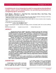
BLER = 10% − Without RLC−AM BLER = 10% − With RLC−AM BLER = 0%
25
20
15
10
5
0 200
300
400
500 600 700 800 SIP INVITE Message size (bytes)
900
1000
Figure 4: SIP INVITE transfer delay with and without RLC-AM
Figures 4 shows the message transfer delay for the SIP INVITE at block error rates (BLERs) of 0% and 10%. The INVITE method is deemed to be the most important method in SIP [1], as it is the only method used to establish a session between participants and normally contains the description of the session to be setup. Hence it is deemed interesting to ascertain its performance. As expected, the message transfer delay increases as the message size increases. It can be seen that with RLC-AM, the transfer delay of the INVITE request is substantially reduced, compared to when no link-layer retransmission is employed, whereby the delay reduction increases as the message size increases. This is because without retransmission at the link-layer, a segment that is lost means that the whole message cannot be recovered at the receiver side and thus, the retransmission (of the whole message) is taken care of at the session-layer, according to the SIP reliability mechanism (when operating over an unreliable transport such as UDP). The results shown in Figure 5 to Figure 12 are presented for the different STATUS report trigger settings with Tgood (mean sojourn time in good state) ranging between 0.5 and 10s, and Tbad equals to 0.5, 2 and 4s for different BLER encountered in the good channel state. Figures 5 and 6 depict the session setup delay for BLER of 1% and 10%, respectively. It is evident that by having both the unsolicited and solicited STATUS report options set, the session establishment delay is reduced compared to only having the solicited feedback set. Also with both the unsolicited and solicited STATUS report trigger configured, the reduction in the session setup delay increases as the channel deteriorates, i.e. when the Tbad value increases and also at a higher BLER. This is because by incorporating unsolicited feedback on top of solicited, the missing PDUs can be recovered faster since retransmissions of missing PDUs can be performed before polling.
Similar observations can also be seen for both the RLC SDU delay (Figures 9-10) and the RLC PDU delay (Figures 11-12), in that when the channel is good, i.e. for a higher Tgood value and a lower Tbad and BLER value, there is little difference in performance, but with both the unsolicited and solicited feedback options set, the reduction in both the RLC SDU and PDU delays increases as the channel gets worse, as compared to just setting the solicited feedback option. For example, by referring to Figure 9 for a Tgood value of 3s and BLER of 1%, the combined solicited and unsolicited scheme gives a reduction in the SDU delay by 20.3% over the solicited scheme when Tbad is 0.5s, but when Tbad is increased to 2 and 4s, the delay reduction now is 21% and 21.2%, respectively. Also when the BLER is increased to 10% as depicted by Figure 10, when Tgood is 3s and Tbad is 2s, the gain in delay reduction achieved by the combined solicited and unsolicited scheme is now 37.5% (as compared to 21% for BLER = 1%). VIII. CONCLUSIONS In this paper, a possible architecture for the integration of S-UMTS into an IP-based terrestrial-UMTS network currently being defined by 3GPP in Release 5 is proposed. End-to-end SIP-based session establishment signalling messages over S-UMTS are shown, along with the associated registration messages. The impact of incorporating a link layer retransmission based on the Radio Link Control acknowledgement mode (RLC-AM) mechanisms on the overall SIP-based session setup performance is also studied. More specifically, the implications of the different triggers for the STATUS report transfer on the session establishment system performance under different channel conditions are examined. From the simulation work, it was found that due to the inherent characteristics of SIP signalling being transactional-based and generous in size, the transport of these packets over the radio interface is not efficient and when transversing over the error-prone wireless link with a larger satellite propagation delay, the performance is severely compromised. With the presence of retransmission at the link layer (RLC), it is seen that the session setup performance can be substantially improved. By having both the unsolicited and solicited STATUS report trigger options set, a better performance in terms of delay and blocking probability is obtained compared to just setting the
solicited feedback, and the gain in performance becomes more evident as the channel condition deteriorates. The work presented here serves as a preliminary step towards the whole study and evaluations of SIP-based session establishment over an integrated satelliteterrestrial UMTS network, as more work still needs to be done to investigate the interaction between the retransmission performed by the RLC-AM and by the higher layers to have a better understanding of crosslayer protocol interactions. It is further envisaged that with suitable compression techniques, the session setup performance can be very much improved. REFERENCES [1] J. Rosenberg, H. Schulzrinne, G. Camarillo, A. Johnston,
J. Peterson, R. Sparks, M. Handley and E. Schooler, "SIP: Session Initiation Protocol," Request for Comments 3261, IETF, June 2002. [2] 3GPP TSG and SA, "Architecture Principles for Release 2000," 3G TR 23.821. [3] D. Boudreau, G. Caire, G. Corazza, R. Gaudenzi, G. Gallinaro, M. Luglio, R. Lyons, J. Romero-Garcia, A. Vernucci and H. Widmer, "Wide-Band CDMA for the UMTS/IMT-2000 Satellite Component," IEEE Trans. Veh. Technol., vol. 51, no. 2, pp. 306-331, March 2002. [4] T. Eyers and H. Schulzrinne, "Predicting Internet Telephony Call Setup Delay," IPTel 2000 (First IP Telephony Workshop), Berlin, Germany, April 2000. [5] E. Kamioka and S. Yamada, "Performance Evaluation of a Seamless communication on 3GPP-based IP Networks," Huntsville Simulation Conference, Alabama, USA, October 2001. [6] G. Foster, M. Pous, A. Sesmun, V. Kenneally and D. Pesch, "Performance Evaluation of UMTS Packet Voice Call Control," 5th European Personal Mobile Communications Conference (EPMCC 2003), Glasgow, Scotland, April 2003, pp. 136-140. [7] L. Fan, R. E. Sheriff and J. G. Gardiner, "Satellite-UMTS Service Provision Using IP-Based Technology," VTC 2000 Spring, Tokyo, Japan, May 2000, pp. 1970-1974. [8] L. Fan, M. E. Woodward and J. G. Gardiner, "Architecture and Protocols in an IP-based Integrated Terrestrial/Satellite Mobile Communication Network," IEEE ICC, Helsinki, Finland, June 2001, pp. 2850-2854. [9] 3GPP TSG Radio Access Networks, "RLC Protocol Specification (Release 5)," 3G TS 25.322, December 2002. [10] ESA 'S-UMTS final report', Alcatel Space Industries, M.G. Françon. [11] 3GPP TSG and SA, "Architectural Requirements (Release 5)," 3G TS 23.221, December 2002. [12] 3GPP TSG CN, "Signalling flows for the IP multimedia call control based on SIP and SDP (Release 5)," 3G TS 24.228, December 2002. [13] J. Rosenberg, H. Schulzrinne, "Reliability of Provisional Responses in Session Initiation Protocol (SIP)," Request for Comments 3262, IETF, June 2002.
[14] J. Rosenberg, "The Session Initiation Protocol (SIP) UPDATE Method," Request for Comments 3311, IETF, October 2002. [15] R. Braden, L. Zhang, S. Berson, S. Herzog, S. Jamin, "Resource ReSerVation Protocol (RSVP) - Version 1 Functional Specification," Request for Comments 2205, IETF, September 1997. [16] 3GPP TSG Services and System Aspects, "General Packet Radio Service (GPRS) Service Description, Stage 2 (Release 5)," 3G TS 23.060, December 2002. [17] 3GPP TSG CN: "Mobile Radio Interface Layer 3 specification; Core Network Protocols; Stage 3 (Release 5)", 3G TS 24.008, December 2002. [18] 3GPP TSG Radio Access Networks, "RRC Protocol Specification (Release 5)," 3G TS 25.331, December 2002. [19] H. Holma and A. Toskala, "WCDMA for UMTS," John Willey & Sons, 2002. [20] T. J. Kostas, M. S. Borella, I. Sidhu, G. M. Schuster, J. Grabiec, and J. Mahler, "Real-time voice over packetswitched networks," IEEE Network, no. 1, January/February 1998, pp. 18-27. [21] 3GPP TSG RAN, "Delay Budget within the Access Stratum, (Release 4)," 3G TR 25.853, March 2001. [22] E. Lutz, D. Cygan, M. Dippold, E. Dolainsky and W. Papke, "The land mobile satellite channel - recording, statistics and channel model," IEEE Transactions on Vehicular Technology, May 1991, pp 375-386. [23] 3GPP TSG GERAN, "A Comparison Between PacketSwitched Call Setup Using SIP and GSM CircuitSwitched Call Setup Using RIL3-CC, RIL3-MM, RIL3RR, and DTAP," GP-000508, Nortel Networks, November 2000. [24] J. Laiho, A. Wacker and T. Novosad, "Radio Network Planning and Optimization for UMTS," John Willey & Sons, 2002.
110
180 Tbad = 0.5s − Solicited Tbad = 2s − Solicited Tbad = 4s − Solicited Tbad = 0.5s − Unsolicited + Solicited Tbad = 2s − Unsolicited + Solicited Tbad = 4s − Unsolicited + Solicited
100
140
Session Setup Delay (s)
Session Setup Delay (s)
90
Tbad = 0.5s − Solicited Tbad = 2s − Solicited Tbad = 4s − Solicited Tbad = 0.5s − Unsolicited + Solicited Tbad = 2s − Unsolicited + Solicited Tbad = 4s − Unsolicited + Solicited
160
80 70 60 50
120
100
80
40 60 30 40
20 10 0
1
2
3
4
5 Tgood (s)
6
7
8
9
20 0
10
Figure 5: Session setup delay for BLER = 1% in good state
4
5 Tgood (s)
6
7
8
9
10
0.8
0.7 0.6 0.5 0.4
0.7 0.6 0.5 0.4
0.3
0.3
0.2
0.2
0.1
0.1
1
2
3
4
5 Tgood (s)
6
7
8
9
Tbad = 0.5s − Solicited Tbad = 2s − Solicited Tbad = 4s − Solicited Tbad = 0.5s − Unsolicited + Solicited Tbad = 2s − Unsolicited + Solicited Tbad = 4s − Unsolicited + Solicited
0.9
Call Blocking Probability
Call Blocking Probability
0.8
0 0
10
Figure 7: Call blocking probability for BLER = 1% in good state
1
2
3
4
5 Tgood (s)
6
7
8
9
10
Figure 8: Call blocking probability for BLER = 10% in good state 10
8 Tbad = 0.5s − Solicited Tbad = 2s − Solicited Tbad = 4s − Solicited Tbad = 0.5s − Unsolicited + Solicited Tbad = 2s − Unsolicited + Solicited Tbad = 4s − Unsolicited + Solicited
7
8
5
4
7 6 5
3
4
2
3
1
2
1
2
3
4
5 Tgood (s)
6
7
8
Figure 9: RLC SDU delay for BLER = 1% in good state
9
Tbad = 0.5s − Solicited Tbad = 2s − Solicited Tbad = 4s − Solicited Tbad = 0.5s − Unsolicited + Solicited Tbad = 2s − Unsolicited + Solicited Tbad = 4s − Unsolicited + Solicited
9
RLC SDU Delay (s)
6
RLC SDU Delay (s)
3
1 Tbad = 0.5s − Solicited Tbad = 2s − Solicited Tbad = 4s − Solicited Tbad = 0.5s − Unsolicited + Solicited Tbad = 2s − Unsolicited + Solicited Tbad = 4s − Unsolicited + Solicited
0.9
0 0
2
Figure 6: Session setup delay for BLER = 10% in good state
1
0 0
1
10
1 0
1
2
3
4
5 Tgood (s)
6
7
8
9
Figure 10: RLC SDU delay for BLER = 10% in good state
10
9
10 Tbad = 0.5s − Solicited Tbad = 2s − Solicited Tbad = 4s − Solicited Tbad = 0.5s − Unsolicited + Solicited Tbad = 2s − Unsolicited + Solicited Tbad = 4s − Unsolicited + Solicited
8 7
Tbad = 0.5s − Solicited Tbad = 2s − Solicited Tbad = 4s − Solicited Tbad = 0.5s − Unsolicited + Solicited Tbad = 2s − Unsolicited + Solicited Tbad = 4s − Unsolicited + Solicited
9 8
RLC PDU Delay (s)
RLC PDU Delay (s)
7 6 5 4
6 5 4
3 3 2
2
1 0 0
1
1
2
3
4
5 Tgood (s)
6
7
8
Figure 11: RLC PDU delay for BLER = 1% in good state
9
10
0 0
1
2
3
4
5 Tgood (s)
6
7
8
9
Figure 12: RLC PDU delay for BLER = 10% in good state
10