To the best of our knowledge, this is the first effort in the .... of the REGISTER J message is different from its domain, RS 2 adds the new entry ... 3 which belong to the same domain, the domain name in the âleaveâ field of the REGISTER J.
SIP Multicast-based Mobile Quality-of-service Support over Heterogeneous IP Multimedia Subsystems Shun-Ren Yang and Wen-Tsuen Chen, Fellow, IEEE Abstract The Universal Mobile Telecommunications System (UMTS) all-IP network supports IP multimedia services through the IP Multimedia Subsystem (IMS). This paper proposes a mobile Quality-of-Service (QoS) framework for heterogeneous IMS interworking. To reduce the handoff disruption time, this framework supports the IMS mobility based on the concept of Session Initiation Protocol (SIP) multicast. In our approach, the mobility of a User Equipment (UE) is modeled as a transition in the multicast group membership. With the concept of dynamic shifting of the multicast group’s members, the flow of actual data packets can be switched to the new route as quickly as possible. To overcome mobility impact on service guarantees, UEs need to make QoS resource reservations in advance at neighboring IMS networks, where they may visit during the lifetime of the ongoing sessions. These locations become the leaves of the multicast tree in our approach. To obtain more efficient use of the scarce wireless bandwidth, our approach allows UEs to temporarily exploit the inactive bandwidths reserved by other UEs in the current IMS/access network. Analytic and simulation models are developed to investigate our resource reservation scheme. The results indicate that our scheme yields comparable performance to that of the previously proposed channel assignment schemes. Keywords: handoff, IP Multimedia Subsystem (IMS), multicast, Quality-of-service (QoS), resource reservation, Session Initiation Protocol (SIP), Universal Mobile Telecommunications System (UMTS).
1
Introduction
To integrate Internet Protocol (IP) with wireless technologies, Universal Mobile Telecommunications System (UMTS) all-IP architecture has been proposed by the Third Generation Partnership Project (3GPP). The UMTS all-IP network supports IP multimedia services (e.g., voice over IP, interactive gaming, video conference, and push to talk over cellular) through the IP Multimedia Subsystem (IMS) [26]. IMS employs the Session Initiation Protocol (SIP) [13] to support multimedia session establishment and control information negotiation. One key feature that makes IMS a promising technology is its access-independence so that IMS services can be provided over any 1
IP connectivity networks (e.g., UMTS, WLAN, broadband access x-Digital Subscriber Line, and WiMAX). As IMS is targeted to offer real-time IP multimedia applications over wireless mobile networks with low bit-rate and high error-rate nature, the two important issues resource provisioning and handoff management should be seriously addressed. The resource provisioning assures the provisioning of sufficient network resources to User Equipments (UEs; the 3G term for mobile hosts) for Quality of Service (QoS) guarantees. The handoff management enables a UE to keep the network connectivity when changing its point of attachment. IMS together with the underlying access and transport networks provides end-to-end QoS. Via IMS, a UE negotiates its capabilities and expresses its QoS requirements during a SIP session establishment or session modification procedure. After negotiating the QoS parameters at the application level, the UE reserves appropriate resources from the access network. IMS assumes that operators negotiate service-level agreements for guaranteeing the required QoS in the interconnection backbone. The IMS QoS mechanism is largely based on the interaction between IMS and the underlying access network. When a UE hands off among IMSs over heterogeneous access networks, the QoS parameters have to be re-negotiated between the newly visited IMS and its underlying access network. The delay of reserving resource along the new data path after the UE’s movement may cause the service disruption for real-time services. Numerous handoff management protocols have been proposed in the literature for IP-based wireless mobile networks. These protocols can be broadly classified according to the layer of their operation, e.g., Mobile IP [14] in the network layer, TCP-Migrate [29] in the transport layer, and SIP in the application layer. Though Mobile IP together with its fast handoff support appears to be the architecturally right protocol for providing IP mobility, it requires significant modifications in the IMS networking infrastructure as well as the UEs. Specifically, the home agent and foreign agent functionalities should be deployed in the IMS network side, while the Mobile IP software package should be installed in the UE side. TCP-Migrate faces the similar problem that it needs to change the TCP protocol implementation for all the UEs. SIP is able to handle terminal mobility in a heterogeneous network environment [28]. Moreover, SIP has been widely adopted in many wireless mobile networks, including IMS, as the signaling protocol for session setup and modification. With these attractive characteristics, SIP is expected to be the right candidate for a handoff management protocol in IMS. However, it has been demonstrated that the SIP terminal mobility 2
may introduce considerable delay [31], which is intolerable to real-time multimedia applications. This is because SIP relies on the transport-layer protocols to deliver its signaling messages and thus is restricted by the performance of TCP or UDP over wireless links. In addition, every time a UE changes its point of attachment, the SIP terminal mobility mechanism has to re-establish the radio and IP connections for the UE. This process is highly time-consuming. Mobility prediction techniques [30] can assist the SIP terminal mobility to reduce the long handoff latency. Nevertheless, mobility prediction algorithms can only offer soft (qualitative) QoS guarantees. The major problem of mobility prediction algorithms is their prediction accuracy. When UEs’ moving behaviors change unexpectedly, mobility prediction algorithms may not perform in an effective manner. To resolve the aforementioned problems arising in IMS when considering SIP handoff management and resource provisioning issues separately, this paper proposes a mobile QoS framework for heterogeneous IMS interworking. To the best of our knowledge, this is the first effort in the literature to integrate mobility and QoS provisioning supports for the IMS networks. Our main contributions are three-fold. Firstly, we propose to support the IMS mobility based on the concept of SIP multicast. By using multicast routing, we avoid IP connection re-establishment during each UE movement. In our approach, the mobility of a UE is modeled as a transition in the multicast group membership. With the concept of dynamic shifting of the multicast group’s members, the flow of actual data packets can be switched to the new route as quickly as possible. We compare the handoff delay performance between our approach and the SIP terminal mobility to justify the benefits of SIP multicast. Secondly, we introduce a resource reservation model in the mobile QoS framework. To overcome mobility impact on service guarantees, UEs need to make QoS resource reservations in advance at neighboring IMS networks, where they may visit during the lifetime of the ongoing sessions. These locations become the leaves of the multicast tree in our approach. To obtain more efficient use of the scarce wireless bandwidth, our approach allows UEs to temporarily exploit the inactive bandwidths reserved by other UEs in the current IMS/access network. Thirdly, we develop analytic and simulation models to study our resource reservation scheme. The analytic and simulation models are different from the existing mobile network handoff models due to the introduction of predictive and temporary reservations. The paper is organized as follows. Section 2 describes the IMS policy-based QoS architecture. Section 3 depicts the adopted SIP multicast mechanism for IMS networks. Section 4 details our proposed SIP multicast-based mobile QoS framework for IMS. Section 5 develops an ana3
! "
$ )
' # #
(
&
%$##
Figure 1: A simplified 3GPP Release 5 IMS network architecture lytic model for the proposed resource reservation scheme in the SIP multicast-based mobile QoS framework. The analytic model is validated against simulation experiments. Section 6 analyzes the handoff delay of our mobile QoS support approach for IMS. Based on the simulation model, Section 6 also investigates the performance of our resource reservation algorithm by numerical examples. Finally, Section 7 concludes the paper.
2
IMS Policy-based QoS Architecture
Before elaborating on the IMS QoS provisioning, we briefly describe a simplified 3GPP Release 5 IMS network architecture (the reader is referred to [22] and references therein for the detailed descriptions), where UMTS is assumed to be the underlying IP access network. As illustrated in Figure 1, this architecture consists of a radio access network, the General Packet Radio Service (GPRS) core network and the IMS network. The GPRS core network connects to the IMS network through Gateway GPRS Support Nodes (GGSNs; see Figure 1(a)). The Home Subscriber Server (HSS; see Figure 1(b)) is the master database containing all user-related subscription information. Both the GPRS and the IMS networks access the HSS for mobility management and session management. A mobile user utilizes a UE (see Figure 1(c)) to access IMS services. To provide a data session for the UE, an IP connection between the UE and the GGSN is established. This connection is specified by a Packet Data Protocol (PDP) context. The PDP context must be activated 4
"
!
Figure 2: IMS policy-based QoS architecture before the UE can access the IMS network. In IMS, the user data traffic and signaling messages are processed separately. IMS user data is transported through the Media Gateways (MGWs; see Figure 1(d)), while IMS signaling is carried out by Proxy Call Session Control Function (P-CSCF; see Figure 1(e)), Interrogating CSCF (I-CSCF; see Figure 1(f)), and Serving CSCF (S-CSCF; see Figure 1(g)). When a UE attaches to the GPRS/IMS network and performs PDP context activation, a P-CSCF is assigned to the UE. The P-CSCF contains limited address translation functions to forward requests (e.g., registration) to the I-CSCF. Authorization for bearer resources in the network (where the UE visits) is also performed by the P-CSCF. The I-CSCF is the contact point for the home IMS network of the destination UE. The role of the I-CSCF is to hide the configuration, capacity, and topology of the IMS network from the external world. The I-CSCF, based on the capabilities queried from the HSS, determines how to route incoming session requests to the S-CSCF and then to the destination UE. The S-CSCF is assigned to serve the UE during the IMS registration. The S-CSCF supports the signaling interactions with the UE for session setup and supplementary services control. Figure 2 depicts the policy-based QoS architecture [26] employed by IMS to ensure that sufficient QoS resources are provided to authorized users. Note that, for the demonstration purpose, we consider the UMTS as the underlying access network. This QoS architecture consists of two main elements: the Policy Decision Function (PDF) and the Policy Enforcement Point (PEP). The 5
PDF is in charge of authorizing usage of network resources such as the bandwidth requested by the UE. The PDF could be integrated with the P-CSCF, or be deployed as a standalone network entity. In the standalone configuration, the P-CSCF communicates with the PDF through the Gq interface. The PEP is a logical entity that carries out actions stipulated by the policy decisions from the PDF. The PEP resides in the GGSN of the UMTS network, and interacts with the PDF via the Go interface. The reader interested in the Gq and Go reference points is referred to [2] and [1] for the details. The relationships between the P-CSCF/PDF, the GGSN/PEP and the UE are briefly described as follows.
The P-CSCF/PDF Functions During the establishment of a SIP session, the UE specifies the QoS requirements in the Session Description Protocol (SDP) description within the SIP messages. The P-CSCF processes the SIP messages and sends the relevant SDP information to the PDF together with an indication of the originator. The PDF authorizes the IP flows of the chosen media components by mapping from SDP parameters to authorized IP QoS parameters for transfer to the GGSN via the Go interface. Besides the QoS requirements, the PDF also examines the source and destination IP addresses and port numbers for traffic policing. Then, the PDF generates an authorization token that uniquely identifies the SIP session across multiple PDP contexts terminated by a GGSN. This token is sent to the UE via SIP signaling so that the UE can use it to identify the associated session flows to the PEP in the GGSN in subsequent transmissions of IP packets.
The UE Functions The UE obtains the authorization token from the P-CSCF. This token is used in the PDP context activation or modification procedure as the binding information. In addition, the authorization token associates the PDP context bearer with the IP flows. When activating or modifying a PDP context for media, the UE has to perform the mapping from SDP parameters to the requested UMTS QoS parameters. The QoS parameters include traffic class (conversational, streaming, interactive or background), guaranteed bit rate, maximum bit rate, etc [26].
6
The GGSN/PEP Functions On receiving the PDP context activation or modification request, the GGSN/PEP asks the PDF for the authorization information. The PDF compares the received binding information with the stored authorization information and returns an authorization decision. The PDF communicates details of the media authorization in the decision to the GGSN/PEP. These details contain IP QoS parameters and packet classifiers related to the PDP context. The GGSN/PEP then maps the authorized IP QoS parameters to the authorized UMTS QoS parameters. Finally, the GGSN/PEP compares the requested UMTS QoS parameters of the PDP context against the authorized UMTS QoS parameters. If the requested UMTS QoS parameters lie between the limits authorized by the PDF, then the PDP context activation or modification request is approved. The packet classifiers from the PDF are referred to as gates. When an IP flow is authorized by the PDF to use the specified network resources, the PEP opens the gate for the flow and effectively commits the network resources to the flow by allowing it to pass through the policing mechanism. On the contrary, if an IP flow is not permitted by the PDF to use the requested resources, the PEP closes the gate and drops the IP packets of the flow.
3
SIP Multicast Mechanism for IMS Networks
This section describes the adopted SIP multicast mechanism for IMS networks, which is based on the proposal in [33]. To support the SIP multicast, an IMS network should employ a new logical entity “Root Server (RS)” that is responsible for forming a multicast tree in the local domain (i.e., the coverage area of the IMS network) and to deliver multicast packets to the group members. Every UE which wants to join a multicast group for receiving multicast packets must register with RS through its local P-CSCF by using REGISTER J message. The REGISTER J and REGISTER L methods are extended from the basic SIP REGISTER method by adding “join” and “leave” fields for joining and leaving a multicast group. Note that, compared with the modifications needed to implement Mobile IP, the SIP multicast mechanism does not require a typical IMS UE to support any additional protocols. Moreover, RS can be integrated into the existing router in each domain. These routers must be capable of performing SIP signaling and managing multicast group membership, rather than executing complicated Mobile IP tunneling operations. In the following subsections, we briefly summarize the concepts of the SIP multicast mechanism. The interested 7
reader is referred to [33] for the detailed descriptions.
3.1 Forming the RS Multicast Tree An RS is active if there exist at least one member of the multicast group in its domain. When an RS is activated, it will join the RS multicast group by sending the RS REGISTER J request with “join” field to the Administrator Server (AS) that is assigned by the IMS network operators to administer the RS multicast tree forming. If the RS is the first one that sends the RS REGISTER J request with “join”, the AS informs it to be the source of the RS multicast tree. On the other hand, if the RS is not the first one to send the RS REGISTER J request, the AS informs it of the source of the multicast tree and redirects it to the source RS. When an RS has no group members in its domain, it sends the RS REGISTER L request to leave the source RS. If the source RS has no group members in its domain and other domains, it will send the RS REGISTER L request to the AS for terminating the multicast session. The source RS can decide to apply any multicast routing protocol to construct its multicast tree. It is assumed that all domain RSs exist and every RS knows the location of its AS assigned by the IMS network operators. All local P-CSCFs know the location of its RS in its domain.
3.2 Registration When a UE moves to a foreign IMS network, it has to register with the local P-CSCF. The purpose of the registration is to join the multicast group by registering with the RS through the local PCSCF for multicast service. Figure 3(a) illustrates the registration procedure. For the scenario in this figure, RS 2 receives the REGISTER J message from UE 1 through its new P-CSCF 2. Note that it is possible that UE 1 moves from a different domain or from the same domain (i.e., the case where multiple P-CSCFs exist in the domain). If the domain name in the “leave” field of the REGISTER J message is different from its domain, RS 2 adds the new entry [P-CSCF 2, UE 1] in its domain group member’s table. It then creates a REGISTER L message and delivers this REGISTER L message to UE 1’s previous RS 1 whose address is given in the “leave” field of the REGISTER J message. RS 1 removes its [P-CSCF 1, UE 1] entry from its domain group member’s table and forwards this REGISTER L message to UE 1’s previous P-CSCF 1 mentioned in the “leave” field of the REGISTER L message. P-CSCF 1 deletes UE 1 from its serving UE list.
8
"# !
$
%&
Figure 3: Registration and session set-up for the SIP multicast
9
Similarly, P-CSCF 2 adds UE 1 in its serving UE list. If UE 1 moves from P-CSCF 2 to P-CSCF 3 which belong to the same domain, the domain name in the “leave” field of the REGISTER J message is the same as RS 2’s domain. In this case, RS 2 updates the entry in its domain group member’s table from [P-CSCF 2, UE 1] to [P-CSCF 3, UE 1]. P-CSCF 3 adds UE 1 in its serving UE list, and P-CSCF 2 deletes UE 1 from its serving UE list.
3.3 Multicast Session Establishment When a correspondent host CH would like to set up a media session with a multicast group G, it should first register with the RS to join the multicast group and be part of the RS multicast tree. In the example of Figure 3(b), CH sends the INVITE message to its local P-CSCF 1 and informs it to set up a media session to the group G. P-CSCF 1 queries its database to obtain the information regarding the RS of group G. It then transfers this INVITE message to RS 1. If RS 1 has group members registered with it, it forwards the INVITE message to all local group members. RS 1 also sends the INVITE message to other RSs in other domains that have the group G members. RS 1 routes the INVITE message to RS 2 that has group members UE 1 and UE 2. Upon receiving the INVITE message from RS 1, RS 2 multicasts the INVITE message to group members UE 1 and UE 2. If UE 1 and/or UE 2 accept this invitation, they/it will send back the 200 OK message to CH. After CH receives the 200 OK, it will respond with the ACK message. When the above signaling exchanges have been completed, the multicast session is established, and the Real-time Transport Protocol (RTP) media can thus be delivered.
4
Proposed SIP Multicast-based Mobile QoS Support for IMS
In this section, we propose a framework to reduce the handoff disruption time when UEs are roaming among heterogeneous IMS networks. In this framework, we propose an extended QoS resource reservation model to enhance utilization of scarce wireless bandwidth. By means of various reservations described below, we are able to preserve the service agreements without degrading QoS for roaming UEs. With our proposal, actual IP datagrams are delivered to a UE using the SIP multicast routing. The mobility of a UE is modeled as a transition in the multicast group membership.
10
4.1 Reservation Model We propose that a UE has to make advance resource reservations along the data flow paths at the IMS/access networks where it may visit during the session is active. The UE not only reserves the requested bandwidth at its current IMS/access network, but also reserves some bandwidths in advance at its neighboring IMS/access networks. In our reservation model, two IMS/access networks are said to be neighbors if they are geographically adjacent to each other. We propose three classes of reservations, namely (1) Conventional Reservation (CR), (2) Predictive Reservation (PR), and (3) Temporary Reservation (TR). CR reserves bandwidth along the data flow from the sender to the current IMS/access network. The data packets are actually traveling over the CR link to the receiver UE. PR reserves bandwidths along the SIP multicast tree from the source to the neighboring IMS/access networks surrounding the current IMS/access network of the UE. Actual data packets are not being transmitted over the PR links. The bandwidths on PR are reserved but not actually allocated. On a link, CR and PR for the same data flow would be merged on the flow merge point. TR temporarily uses the inactive bandwidths reserved by other data flows in the current IMS/access network. When the UE which made the PR moves into the current IMS/access network (i.e., when the PR made by this UE becomes active), the temporary usage of the inactive bandwidths should be preempted. We design the reservation model to be as general as possible. In this model, the detailed resource allocations will depend on the criteria specified in the underlying resource reservation algorithms. For example, the resource reservation algorithm (i.e., Algorithm 1) in Subsection 5.1 for the analytic analysis is developed based on the first-come-first-serve predictive reservation discipline. Other more sophisticated resource reservation algorithms proposed in the literature can also be applied to our reservation model to guarantee the fairness between session flows or to maximize the utilization of available bandwidth. Referring to Figure 4, we give an example for various classes of reservations. There is a UE M establishing a session in IMS C. It makes resource reservation in IMS C and reserves bandwidth along the path upstream toward the sender using CR. In addition to the reservation in the current IMS/access network, UE M makes PRs in neighboring IMS B and IMS D as well. Moreover, UE M reserves resources in advance along the paths from IMS B and IMS D to the sender. The CR and PR made by UE M are merged on the merge point, which is an intermediate RS on the 11
! "##
%$Figure 4: Mobile QoS support for IMS based on the SIP multicast reservation route upstream toward the sender. The sender transmits actual data packets traveling over the CR link downstream toward UE M in IMS C. The bandwidths are reserved but not actually allocated along the paths from the merge point to IMS B and IMS D. Actual data packets are not being transmitted over the PR links. Once UE M was moving to IMS B, the PR from the merge point to IMS B is switched into CR. Then, actual data packets are being transmitted over that link. On the other hand, the original CR from the merge point to IMS C is switched to PR.
4.2 P-CSCF in IMS networks In our framework, the P-CSCF in an IMS network is the entity that acts as an agent for a UE to make various reservations along the data paths from the current and the surrounding IMS/access networks toward the sender. The current P-CSCF establishes the CR from the UE to the sender. The neighbor P-CSCFs will make the PRs on behalf of the UE in the neighboring IMS/access networks. The UE can discover the current and neighbor P-CSCFs via the DHCP DNS procedure standardized in 3GPP. In the DHCP DNS procedure, the UE sends a DHCP query to a DHCP
12
server to request a list of the P-CSCFs’ domain names. For the returned domain names, the UE then performs a DNS query to find the corresponding IP addresses. When the UE moves to a new location, the CR from the sender to its previous location is changed to a PR and the PR from the sender to the new location is changed to the CR. The data flow must be switched to the new CR link as well. More specifically, once the UE is moving into an area managed by a neighbor P-CSCF, the current P-CSCF will be notified by the handoff process and will then issue a message to update the reservation states along the upstream of the original CR link. Upon receiving this update message, an intermediate RS switches the CR state to a PR state and forwards the message upstream until the merge point. Also, the original current P-CSCF will send a message to the neighbor P-CSCF of the IMS/access network that the UE moves into to initiate changing of the reservation states. This neighbor P-CSCF will issue a message to update the reservation states along the upstream of its original PR link. On receiving this update message, the intermediate RSs switch the PR states to the CR states and forward the message upstream until the merge point. Note that, the other neighbor P-CSCFs can explicitly tear down the unnecessary reservations on behalf of the UEs which are moving out of their IMS/access networks.
4.3 Mobile QoS Support based on the SIP Multicast To guarantee the QoS and accelerate the handoff process, our design supports mobile QoS for heterogeneous IMS interworking based on the SIP multicast. With our approach, actual IP datagrams are delivered to a UE using the SIP multicast routing. As described in Section 3, there is one SIP multicast tree rooted at each source node. A new UE joining a multicast group results in establishing a new branch in the multicast tree. A UE leaving a multicast group causes a branch in the multicast tree to be pruned. In a heterogeneous IMS networks environment, we model the mobility of a UE as a transition in the multicast group membership. Movement of a UE from one IMS network to another is modeled as a multicast-join in the new location, and a multicast-leave from the old location. Mapping to our resource reservation model, when a receiver UE launches a reservation, join operation is not only initiated from the current P-CSCF but also from the neighbor P-CSCFs surrounding the current location. These join operations result in the construction of new branches of the multicast tree rooted at the sender. Once new branches have been formed, the current P-CSCF and the neighbor P-CSCFs will issue reservation requests. The CR message from the current P-CSCF is propagated toward the sender along the multicast tree, and the PR messages 13
from the neighbor P-CSCFs are forwarded in the same manner. If these reservations are successful, the data packets can be transmitted over the CR link and resources on the PR links are reserved for this data flow. When the receiver UE is moving from one location to another, the flow of data packets can be switched to the new route as quickly as possible. We suggest that the multicast tree be modified dynamically every time the UE is roaming to a neighboring IMS/access network. Modification of the multicast tree is achieved by changing the multicast group’s members. More specifically, the serving UE lists and domain group member’s tables of the involved P-CSCFs and RSs are updated to reflect the UE’s movement. With this design, the flow of data packets can be switched to the new route as soon as a handoff occurs. Even though this method requires a lot more background processing and consumption of bandwidth, we can eliminate the need for re-routing the data path during handoff. The resource reserved along the old path may be released when the multicast tree branch is pruned after a time-out, or by explicit request from the UE or the P-CSCF. Considering the example shown in Figure 4, the receiver UE M establishes a connection in IMS C. In order to reserve resource in advance, UE M sends a REGISTER J message containing the multicast address of the data flow to the neighbor P-CSCFs in IMS B and D for joining the multicast group associated with the session. The P-CSCFs in IMS B and D forward the REGISTER J message to the associated RSs. Consequently, IMS B, C, and D form the leaves of the multicast tree rooted at the sender. When UE M moves from IMS C to IMS B, the P-CSCF in IMS C will inform the P-CSCF in IMS A to join the multicast group. Furthermore, the P-CSCF in IMS C will tear down the PR in IMS D. Thus, when UE M moves to the new IMS B, a join operation is initiated which results in the construction of a new branch in the multicast tree. Once the new branch is formed, UE M initiates the PR in IMS A. This results in resource being reserved along the new branch. The resource reserved in IMS D will then be released when the old multicast tree branch is pruned. Besides, the CR from the merge point to IMS C is changed to a PR and the PR from the merge point to IMS B is changed to the CR.
5
An Analytic Model
This section develops an analytic model to investigate our proposed resource reservation scheme. Compared with the wireline backbone connection, the radio bandwidth is more scarce and is often the bottleneck of the QoS provisioning. Therefore, our reservation scheme focuses only on the
14
channel resource assignment in the various underlying access networks. This analytic model is different from the existing mobile network handoff models [3, 5, 7, 10, 12, 18, 19, 23, 24, 25, 32] due to the introduction of PR and TR besides the traditional CR reservation. For the analytical tractability, our model makes the following assumptions. • An IMS/access network supports c channels (frequencies, time slots, spreading codes or a combination of these depending on the underlying access technology). • The arrivals of new and handoff sessions to an IMS/access network are Poisson distributed with rates λo and λh , respectively. Note that λh is correlated with other parameters including new session arrival rate, UE mobility, etc. • The session holding time tc is exponentially distributed with mean 1/µ. • The residence time tm,i of a UE in an IMS/access network i follows exponential distribution with mean 1/η. Although the residence time is typically non-exponential in a particular IMS/access network, the analysis based on the exponential assumption has been widely used [15, 17, 34] and does provide useful mean value information for the output measures. Our analytic analysis is validated against simulation experiments (will be elaborated later in this section) for justifying the correctness of both the analytic and simulation results. To investigate more realistic network situations, the above assumptions can be easily relaxed in our simulation model to accommodate general statistical distributions. The following output measures are evaluated in our study. • po (the new session blocking probability): The number of new session blockings divided by the number of new sessions. • pf (the forced termination probability): The number of forced terminations owing to failed handoffs divided by the number of handoffs. • pnc (the session incompletion probability; i.e., the probability that a session is either blocked or forced to terminate): The sum of the numbers of new session blockings and forced terminations divided by the number of new sessions. Note that p nc 6= po + pf . The notation used in the analytic model is also listed in Table 1. 15
Table 1: The input parameters and output measures Notation c I C P T λo λh 1/µ 1/η po pf pnc
Description System Parameters the number of channels supported in an IMS/access network the set of idle channels the set of CR channels the set of PR channels that are not occupied by any TR sessions the set of TR channels that temporarily use the PR reservations Traffic and Mobility Parameters the new session arrival rate to an IMS/access network the handoff session arrival rate to an IMS/access network the mean of the session holding time the mean of the UE residence time in an IMS/access network Output Measures the new session blocking probability the forced termination probability the session incompletion probability
5.1 The Resource Reservation Algorithm Consider the channel resource assignment in an IMS i. Let I be the set of idle channels, C be the set of CR channels, P be the set of PR channels that are not occupied by any TR sessions, and T be the set of TR channels that temporarily use the PR reservations. Suppose that each session arrival requests one channel for communication. Based on the reservation model in Section 4, the detailed resource (i.e., channel) reservation algorithm for our analytic analysis is presented in Algorithm 1.
Note that, the PRflag in Algorithm 1 indicates whether a handoff session s from IMS j had
previously made a successful PR reservation in the newly visited IMS i. We use the example in Figure 4 to explain Algorithm 1 as follows. When UE M requests to establish a new session s in IMS C, line 3 checks if any idle channel exists in IMS C for serving s. If so, a CR channel out of I is allocated to s in line 4, and the cardinalities of the sets I and C in IMS C are updated by using |I| − − and |C| + +. Moreover, line 5 makes PR reservations for s in IMS B and IMS D. It is possible that the PR reservations in IMS B and/or IMS D are not successful due to no idle channels. In this case, the corresponding PRflag of s in IMS B and/or IMS D should be set to 0. On the other hand, if IMS C does not have any idle channel but its set P of PR channels is not empty, line 7 allocates a TR channel out of P to s, and updates the cardinalities of the sets P and T in IMS C by using |P| − − and |T | + +. Note that our algorithm does not allow a TR session to make PR reservations. If there is no idle or PR channel in IMS C to serve s, s is blocked in line 9. 16
Algorithm 1 T HE R ESOURCE R ESERVATION A LGORITHM 1: if a session s arrives to IMS i then 2: if s is a new session then 3: if i.|I| > 0 then 4: Allocate a CR channel out of the idle channel pool to s; i.|I| − −; i.|C| + +; 5: Make PR reservations for s in the neighbors of IMS i. 6: else if i.|I| = 0 and i.|P| > 0 then 7: Allocate a TR channel out of the PR channel pool to s; i.|P| − −; i.|T | + +. 8: else if i.|I| = 0 and i.|P| = 0 then 9: The new session s is blocked. 10: end if 11: else if s is a handoff session from IMS j then 12: if PRflag=1 and i.|P| > 0 then 13: Allocate a CR channel out of the PR channel pool to s; i.|P| − −; i.|C| + +; 14: Make new PR reservations for s in the neighbors of IMS i. 15: else if PRflag=1 and i.|P| = 0 then 16: Select a TR session r for replacement; Allocate the reclaimed channel from r to s as
s’s CR channel; The session r is forced to terminate; i.|T | − −; i.|C| + +; 17: Make new PR reservations for s in the neighbors of IMS i. 18: else if PRflag=0 and i.|I| > 0 then 19: Allocate a CR channel out of the idle channel pool to s; i.|I| − −; i.|C| + +; 20: Make new PR reservations for s in the neighbors of IMS i. 21: else if PRflag=0, i.|I| = 0 and i.|P| > 0 then 22: Allocate a TR channel out of the PR channel pool to s; i.|P| − −; i.|T | + +. 23: else if PRflag=0, i.|I| = 0 and i.|P| = 0 then 24: The handoff session s is forced to terminate. 25: end if 26: end if 27: end if 28: if a session s departs from IMS i then 29: if s is a CR session then 30: if s is a completed session then 31: Release all the PR reservations for s in the neighbors of IMS i. 32: else if s is a handoff session then 33: Release the obsolete PR reservations for s in the neighbors of IMS i. 34: end if 35: if i.|T | > 0 then 36: Select a TR session r, and allocate the CR channel from s to r; i.|T | − −; i.|P| + +; 37: Make PR reservations for r in the neighbors of IMS i. 38: else 39: i.|I| + +; i.|C| − −. 40: end if 41: else if s is a TR session then 42: i.|T | − −; i.|P| + +. 43: end if 44: end if
17
When UE M with the ongoing session s moves from IMS C to IMS B, lines 12-25 are executed to handle the handoff-in procedure for IMS B, while lines 29, 33 and 35-43 are executed to handle the handoff-out procedure for IMS C. Five cases are possible in the handoff-in procedure. If UE M had previously reserved a PR channel in IMS B and the set P in IMS B is not empty, line 13 allocates a CR channel out of P to s. If UE M had previously reserved a PR channel in IMS B but all the PR channels in IMS B are temporarily used by TR sessions, line 16 selects a TR session r for replacement, and allocates the reclaimed channel from r to s as s’s CR channel. In this case, the session r is forced to terminate. If UE M had not previously made a successful PR reservation in IMS B but IMS B has idle channels, line 19 allocates a CR channel out of I to s. In the above three cases, the cardinalities of the involved sets should be adjusted accordingly. Besides, lines 14, 17 and 20 make new PR reservation for s in IMS A. If UE M had not previously made a successful PR reservation in IMS B, B.|I| = 0 but B.|P| > 0, a TR channel out of P is allocated to s in line 22, and the cardinalities of the sets P and T in IMS B are updated by using |P| − − and |T | + +. Finally, if UE M has no PR reservation in IMS B, B.|I| = 0 and B.|P| = 0, line 24 forces s to terminate. The handoff-out procedure for s in IMS C is summarized below. If s was a TR session when in IMS C, then the cardinalities of the sets P and T in IMS C are increased by one and decreased by one, respectively. Otherwise, if s was a CR session, then the cardinality of the set I is increased by one and the cardinality of the set C is decreased by one. Furthermore, the channel released by s is used to serve a TR session if such a TR session exists in IMS C (line 36). At last, the obsolete PR reservation for s in IMS D is released (line 33). When UE M completes the session s in IMS B, the steps for the handoff-out procedure are performed except that instead of line 33, line 31 releases all the PR reservations for s in IMS A and IMS C.
5.2 The Derivations for the po and pf Probabilities Consider Figure 5. Suppose that a session arrives to a UE when the UE is in IMS 0. If a channel is assigned to the new session, the channel is released when the session is completed or the UE moves out of IMS 0. Let τm,0 be the period between the arrival of the session and when the UE moves out of IMS 0. Then, the channel occupation time tdo of the session in IMS 0 is tdo = min(tc , τm,0 ). 18
Figure 5: The timing diagram Suppose that a session successfully hands off i times. Let tc,i be the period between the time when the UE moves into IMS i and the time when the session is completed. The period t c,i is referred to as the residual life of tc . Then, the channel occupation time tdh of the handoff session in IMS i is tdh = min(tc,i , tm,i ).
Assume that the random variable τm,0 has a density function rm (τm,0 ). Since the session arrivals to an IMS form a Poisson process, a session arrival is a random observer of the time interval t m,0 . Denote fm (tm,i ) as the probability density function of tm,i . From [27], we have Z ∞ fm (τ )dτ = fm (t) = ηe−ηt . rm (t) = η τ =t
The expected values E[tdo ] and E[tdh ] are derived as follows. Since tdo = min(tc , τm,0 ), we have Pr[tdo > τ ] = Pr[min(tc , τm,0 ) > τ ] = Pr[tc > τ, τm,0 > τ ] = Pr[tc > τ ] Pr[τm,0 > τ ] (1)
= e−(µ+η)τ . Since tdo is a nonnegative random variable, the mean E[tdo ] can be computed as Z ∞ E[tdo ] = Pr[tdo > τ ]dτ.
(2)
0
Substituting (1) into (2), we obtain E[tdo ] =
1 . µ+η
(3)
From the memoryless property of the exponential tc distribution, fc,i (tc,i ) = µeµtc,i , and for i > 0, similar to the derivation for E[tdo ] we have E[tdh ] = E[min(tc,i , tm,i )] = 19
1 . µ+η
(4)
In our resource reservation algorithm, a new session is blocked if both the number of idle channels |I| and the number of non-occupied PR channels |P| in the current IMS/access network are equal to zero. In other words, a new session is blocked if the c channels of the IMS/access network are all in use (either “conventionally” or “temporarily”). When an ongoing session is handed off to a neighboring IMS/access network, one of the following two forced termination cases could occur. In the first case, the handoff session did not make the PR successfully in this newly visited IMS/access network, and the IMS/access network’s |I| = |P| = 0. Under this circumstance, the handoff session is itself forced to terminate. In the second case, the handoff session has previously reserved a PR channel in the newly visited IMS/access network, but the IMS/access network’s PR channels are totally occupied by the TR sessions. In this case, the handoff session will choose a TR session for replacement. Since the selected TR session can not find any idle channels or PR channels to continue the communication (i.e., |I| + |P| = 0), it is forced to terminate. Note that, due to the memoryless property of the exponential distribution, the handoff session and the candidate TR sessions for replacement are indistinguishable in terms of the residual session holding time and the residual IMS/access network residence time. As a result, whether the replaced TR session or the handoff session is forced to terminate will not affect the forced termination probability pf . On the other hand, if the session holding time or the IMS/access network residence time is not exponentially distributed, the TR session replacement policies may affect the pf performance, which will be investigated by using simulation experiments in the next section. Based on the above discussion, a new (handoff) session is blocked (force-terminated) if |I| + |P| = 0 for the visited IMS/access network, and thus we have po = p f . The system under study can then be modeled as an M/G/c/c blocking queue [8] where the mean service times for a new session and a handoff session are given in (3) and (4), respectively. Since λo and λh are the new session arrival rate and the handoff session arrival rate to an IMS/access network, the traffic intensity ρ for the blocking queueing system is ρ = λo E[tdo ] + λh E[tdh ] λo + λ h . = µ+η
20
(5)
From [8, pages 244–247], we derive po and pf as (ρc /c!) , po = pf = B(ρ, c) = Pc i i=0 (ρ /i!)
(6)
where B(ρ, c) is the Erlang’s loss formula.
5.3 The Derivations for the Handoff Traffic λh and the pnc Probability Suppose that an IMS/access network is in equilibrium where the handoff session arrival rate λ h is identical to the handoff session departure rate. This assumption has been shown to be reasonable for large-scale homogeneous network structures [19]. We note that a session will be handed off from an IMS i to its neighbors when: • the session is a new session at IMS i (not blocked with probability 1 − p o ), and the session is not completed before the UE leaves IMS i (with probability Pr[t c > τm,0 ]); • the session is a handoff session at IMS i (not forced to terminate with probability 1−p f ), and the session is not completed before the UE leaves IMS i (with probability Pr[t c,i > tm,i ]). Therefore, we have λh = λo (1 − po ) Pr[tc > τm,0 ] + λh (1 − pf ) Pr[tc,i > tm,i ].
(7)
Since both tc and tc,i have the exponential distribution with rate µ and both τ m,0 and tm,i have the exponential distribution with rate η, Pr[tc > τm,0 ] = Pr[tc,i > tm,i ]. We derive the probability Pr[tc > τm,0 ] as follows. Z ∞ Z tc Pr[tc > τm,0 ] = tc =0
(8)
ηe−ητm,0 µe−µtc dτm,0 dtc
τm,0 =0
η = . η+µ
(9)
From (6), (8) and (9), (7) is re-written as λh =
λo (1 − po )
�
1 − (1 − po ) 21
η η+µ
�
�
η η+µ
�.
(10)
Given λo , λh , po and pf , the probability pnc has been derived formally in [20]. [19] gave another intuitive derivation for pnc , which is reiterated below to keep this paper self-contained. In a period 4t, there are λo 4t new session arrivals to an IMS. These new sessions generate λh 4t handoff sessions. Among these new/handoff sessions, the number of blocked sessions is p o λo 4t+pf λh 4t. Thus, pnc is pnc
po λo 4t + pf λh 4t = = po + λo 4t
�
λh λo
�
pf .
(11)
Substituting (10) into (11), we have pnc =
po 1 − (1 − po )
�
η η+µ
�.
(12)
The probabilities po , pf and pnc can be computed by applying the iterative technique [9, 19] and the equations derived in this section. Algorithm 2 shows the details of the derivation. Algorithm 2 T HE I TERATIVE A LGORITHM Input parameters: λo , µ, η, and c. Output measures: λh , po , pf , and pnc . Step 1. Select an initial value for λh . Step 2. Compute po and pf by using (5) and (6). Step 3. λh,old ← λh . Step 4. Compute λh by using (10). Step 5. If |λh − λh,old | > δλh then go to Step 2. Otherwise, go to Step 6. Note that δ is a pre-defined value. 8: Step 6. The values for λh , po and pf converge. Compute pnc by using (12). 1: 2: 3: 4: 5: 6: 7:
5.4 Simulation Validation We have developed a discrete-event simulation model to validate against our analytic analysis. Following the simulation approach proposed in [23], the model defines SESSION ARRIVAL, SESSION COMPLETION, and HANDOFF events to simulate the session traffic and mobility behaviors of IMS UEs. In the simulation experiments, we consider a 8 × 8 wrapped mesh IMS structure (see Figure 6) where a node (a square box) represents an IMS/access network. It has been proven that the 8 × 8 wrapped mesh topology is capable of accurately simulating very large mobile telecommunications networks [21]. The mobility activities of UEs in the simulation are described by a two-dimensional random walk [27]. In the random walk, a UE stays in an IMS/access network for a period of time, which is governed by the IMS residence time distribution. Then the UE moves to one of the four neighboring IMS/access networks with the same routing probabilities 0.25. Table 2 compares the analytic and simulation results, where the mean session holding time 1/µ is 22
Figure 6: The IMS network topology considered in the simulation Table 2: The comparison between the analytic and simulation results (1/µ = 3 min, 1/η = 30 min, and c = 50) λo (unit: µ) po (Analytic) po (Simulation) Error pf (Analytic) pf (Simulation) Error pnc (Analytic) pnc (Simulation) Error
40 1.8325% 1.82927% 0.0176% 1.8325% 1.82491% 0.4141% 2.0121% 2.01306% 0.0477%
50 60 70 9.9409% 20.3233% 29.5698% 9.95647% 20.2983% 29.5404% 0.1566% 0.123% 0.0994% 9.9409% 20.3233% 29.5698% 9.95056% 20.2517% 29.5663% 0.0971% 0.3523% 0.0118% 10.8274% 21.9103% 31.5926% 10.843% 21.8781% 31.562% 0.144% 0.146% 0.0968%
80 37.2046% 37.1753% 0.0456% 37.2046% 37.1938% 0.02902% 39.4571% 39.4325% 0.0623%
90 43.4609% 43.4216% 0.0904% 43.4609% 43.4405% 0.0469% 45.8158% 45.774% 0.0912%
3 min, the mean UE residence time 1/η is 30 min, and the number of channels c in an IMS/access network is 50. For the demonstration purpose, we only show the results for the random TR session replacement policy. The table indicates that the error rate (discrepancy) between analytic analysis and simulation is within 0.5% in all cases. It is clear that the analytic analysis is consistent with the simulation results.
6
Performance Evaluation
In this section, we analyze the handoff delay of our mobile QoS support approach for IMS, and examine the performance of the resource reservation algorithm.
23
Figure 7: Network configuration used for the handoff delay analysis
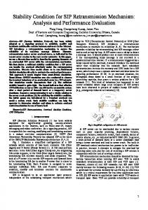
6.1 Analysis of Handoff Delay In this subsection, we make an analytic comparison between our approach and the basic SIP terminal mobility mechanism implemented by Wu et al. [31] in terms of the handoff delay. Consider the example where a UE is handing off from an IMS over WLAN to an IMS over UMTS. The considered network configuration is depicted in Figure 7. Let D Handof f and DHandof f be the handoff 0
00
delays associated with the SIP terminal mobility mechanism and our approach, respectively. The DHandof f delay can be essentially divided into two parts: 0
• the delay during the attachment procedures including GPRS Attach and PDP Context Activation; • the delay due to location update using the SIP re-INVITE message. The numbers of signaling messages for GPRS Attach, PDP Context Activation, and SIP location update are eight, eight, and two, respectively. Because of the space limitation, we do not present the corresponding message flows in this paper. The interested reader is referred to [31, Figure 2] for the details. The DHandof f delay therefore can be expressed as 0
0
0
DHandof f = DAttach + DP DP + DSIP , where DAttach is the message transport delay for GPRS Attach, DP DP is the message transport delay for PDP Context Activation, and DSIP is the transmission delay of SIP location update. The 0
DSIP delay can be further expressed as 0
0
DSIP = DU E + DRLP + DCSCF + ∆I + DSender , 24
Handoff delay (ms)
3000
Queueing/processing delay of D'Handoff Queueing/processing delay of D''Handoff Wireless delay of D'Handoff Wireless delay of D''Handoff
2500 2000 1500 1000 500 0 0.01
0.02
0.03
0.04
0.05
0.06
0.07
0.08
0.09
0.1
Frame error rate
Figure 8: Handoff delay vs. channel frame error rate where DU E is the queueing delay at the UE, DRLP is the transport delay for a packet over an RLP link in UMTS network, DCSCF is the queueing delay at the CSCF servers (including P-CSCF, I-CSCF and S-CSCF), ∆I is the Internet delay in transmitting of SIP messages, and DSender is the queueing delay at the sender. To compute the queueing delays DU E , DCSCF and DSender , an M/M/1 queueing model is assumed for the UE as well as the CSCF servers while a priority-based M/G/1 model is assumed for the sender. Besides the queueing delay components, DAttach , DP DP and DRLP comprise the wireless delay, which should take into account the error and transmission delay characteristics of wireless channels. To compute the message transmission delay over a wireless link in the UMTS radio access networks during the GPRS Attach, PDP Context Activation, and SIP location update procedures, the probabilistic delay models proposed in [4] are adopted for correct frame and packet transmission over a UMTS wireless link under various link error conditions. Figure 8 shows the handoff delay DHandof f (obtained in [31]) as a function of channel frame error rate, where the 0
GPRS radio access bandwidth of the UMTS network is 128 kb/s and the SIP-based multimedia session arrival rate is 50/s. The figure indicates that the wireless delay (i.e., D Attach + DP DP + DRLP ) for the considered frame error rate range is about 1.5 s, and the queueing/processing delay (i.e., DU E + DCSCF + ∆I + DSender ) amounts to about 175 ms. The handoff delay DHandof f is 0
dominated by the wireless delay. It should be stressed that the D Handof f value is underestimated 0
since the signaling for QoS reservation is disregarded. We follow the same method to derive the handoff delay DHandof f for our proposed approach. 00
Based on the SIP multicast and resource reservations, the GPRS Attach and PDP Context Activation procedures are not required in our approach. The UE can use the reserved layer-2 link and
25
the pre-negotiated encryption key to directly attach to the newly visited IMS/UMTS network. The link-layer and network-layer handoff delay in our framework results only from a pair of signaling message exchange between the UE and the new IMS/UMTS network to indicate that the UE with predictive resource reservation has moved into the coverage area of the new IMS/UMTS network. However, compared with the link-layer and network-layer delays of the existing IP access networks, the transmission delay of a pair of signaling messages is sufficiently small and thus can be ignored. Our approach requires a REGISTER J message to be sent from the UE to update the SIP multicast group membership. In addition, the PR from the merge point RS to the new IMS should be changed to the CR. Therefore, the DHandof f delay can be expressed as 00
00
00
DHandof f = DSIP + DQoS , where DSIP is the transmission delay of SIP multicast tree update, and DQoS is the QoS path 00
update delay. The DSIP delay can be further expressed as 00
00
DSIP = DU E + DRLP + DP −CSCF + ∆I + DRS , where DRS is the queueing delay at the involved RSs (three in this example). Following the statistical data from [11], we assume that the QoS path update delay of each RS is 2 ms. Then, DQoS is computed as 2×3 = 6 ms. The wireless delay component (i.e., D RLP ) of DHandof f is 00
estimated as 1500/18 ' 85 ms (since compared with the eighteen signaling messages used in the SIP terminal mobility mechanism, our approach only transmits one signaling message over the air interface), and the queueing/processing delay component (i.e., D U E + DP −CSCF + ∆I + DRS + DQoS ) is estimated as 185 ms. Figure 8 shows the total handoff delay D Handof f as a function of 00
channel frame error rate. The above analysis indicates that under the considered network configuration and moving scenario, DHandof f is about 1675 ms while DHandof f is only about 270 ms. It is clear that our proposed 0
00
approach significantly outperforms the SIP terminal mobility mechanism in terms of the handoff delay. We also note that, the longer the distance between the remote sender and the receiver UE, the larger the difference between DHandof f and DHandof f . It has been shown that for delay-sensitive 0
00
services such as multimedia streaming, the maximum handoff delay should ideally be less than 100 ms and not more than 200 ms [31]. Our approach, based on the SIP multicast, provides an effective means for supporting heterogeneous IMS handoff even in the low-bandwidth UMTS environment. 26
6.2 Analysis of Resource Reservation Algorithm Based on the simulation validated by the analytic model described in the previous section, this subsection investigates the performance of our resource reservation algorithm. In the simulation experiments, we assume that the IMS residence time tm,i is Gamma distributed with mean 1/η and variance Vm , and the session holding time tc is Gamma distributed with mean 1/µ and variance Vc . The Gamma distribution with shape parameter α and scale parameter β (i.e., mean is α/β and variance is α/β 2 ) has the following density function f (t) = where Γ(α) =
Z
βe−βt (βt)α−1 Γ(α)
for t ≥ 0
∞
z α−1 e−z dz is the Gamma function. It has been shown that the distribution z=0
of any positive random variable can be approximated by a mixture of Gamma distributions (see [16, Lemma 3.9]). The Gamma distribution was used to model UE traffic/mobility activities in many studies [3, 5, 6], and is used in this paper to investigate the impacts of variances for IMS residence times and session holding times. In the experiments, we assume that an IMS/access network supports c = 50 channels. To examine the impacts of different TR session replacement policies, we consider the following replacement policies in Figures 9-12: • One of the TR sessions is randomly selected for replacement (the curves marked by �). • Let tcr,k be the time interval between when a TR session k is initiated and when a replacement request arrives. The TR session with the longest tcr,k interval is selected for replacement (the curves marked by ◦). • Contrary to the “◦” policy, the TR session with the shortest t cr,k interval is selected for replacement (the curves marked by •). • Let tmr,k be the time interval between when a TR session k begins its communication in the current IMS/access network and when a replacement request arrives. The TR session with the longest tmr,k interval is selected for replacement (the curves marked by /). • Contrary to the “/” policy, the TR session with the shortest t mr,k interval is selected for replacement (the curves marked by .).
27
• Let Nhr,k be the number of handoffs for a TR session k before a replacement request arrives. The TR session with the highest Nhr,k /tcr,k value is selected for replacement (the curves marked by ?). The effects of several input parameters on the output measures p o , pf and pnc are shown in Figures 9-13 (where the y-axes for subfigures (a), (b) and (c) are po , pf and pnc , respectively), and are discussed as follows. Effects of the TR session replacement policies. Figures 9-12 indicate that different TR session replacement policies have similar po , pf and pnc performance. The reason is given as follows in terms of the new session traffic λo and the UE mobility rate η. Case I. When λo is small, IMS/access networks are not overloaded. In this case, a handoff session has high probability to find an idle channel or a free PR channel to transmit packets. Therefore, TR session replacements seldom occur, and different replacement policies have insignificant impacts on po , pf and pnc . Case II. When λo is large, the channels are fully occupied, and it is less likely that ongoing sessions can successfully reserve PR channels in the neighboring IMS/access networks. In this case, the handoff sessions (without PR reservations) will not replace TR sessions. Hence, po , pf and pnc are not affected by the TR session replacement policies. Case III. When η is small, UEs move infrequently. Therefore, TR session replacements happen rarely, and have negligible influences on the po , pf and pnc performance. Case IV. When η is large, po and pf are small (see the effects of η below). This means that PR reservations are easier, and few TR session replacements are required when handoff sessions arrive. Again, po , pf and pnc are insignificantly influenced by the TR session replacement policies. Effects of λo . Figure 9 plots po , pf and pnc as functions of λo where η = 2µ, Vm = 1/η 2 , and Vc = 1/µ2 . The figure indicates that po , pf and pnc are not affected by λo when λo is sufficiently small (namely, λo < 30µ). As λo increases, it is more likely that the incoming new sessions or handoff sessions could not find any idle or PR channels for communication. Consequently, po , pf and pnc increase accordingly. 28
100
100
90
90
80 70 60 50 40 30 20 10 0
..•◦�/.?. .... .•◦�/.?.. . . .. .•◦�/.?.. .... . .•◦�/.?.. ..... . .. .•◦�/.?. ..... .. •◦�/.?... ..... .. •◦.. ..�/.?. . ... •◦�/.?........•◦�/.?.........•◦�/.?........•◦�/.?.. 101
102
103
λo (unit: µ) (a) po (%)
80 70 60 50 40 30 20 10 0
100 ...�◦•/.?. .... ..�◦•/.?. . . .. .�◦•/.?.. ..... . ..�◦•/.?. .. .... �◦•/.?.. ... ..... �◦•/.?... ... .... .. ..�◦•/.?. .. . . �◦•/.?........�◦•/.?.........�◦•/.?.........�◦•/.?. 101
102
90 80 70 60 50 40 30 20 10 0
103
.....•◦�/.?. .....•◦�/.?.. •◦�/.?.... . . . ... ..•◦�/.?. ..... .•◦�/.?. ... ..... .•◦�/.?.. ... .... .. ... •◦�/.?.... .. .. ..... . .. ... ◦ � ? . / • . . . •◦�/.?........•◦�/.?.........•◦�/.?..... 101
λo (unit: µ) (b) pf (%)
102
103
λo (unit: µ) (c) pnc (%)
Figure 9: Effects of λo on po , pf and pnc (η = 2µ, Vm = 1/η 2 , Vc = 1/µ2 ) 40 �◦•/.?........�◦•?....... /. .�◦•/.?...... ...�.. ◦•/.?.... 35 .... �◦•/.?.... ... 30 ... ... �◦•/.?.... 25 ... ... ... 20 ... �◦•/.?.... ... 15 ... ... .�•.. ◦/.?.. 10 ... ... �◦•/.?..... 5 ..... �◦•/.?....... �◦•/.? 0 −2 0 10 10 102 η (unit: µ) (a) po (%)
40 �◦•?..............�◦•?.......... /. /.......�◦•/.?....... ..�◦•/.?... .... 35 ... �◦•/.?... ... 30 ... ... �◦•/.?.... 25 ... ... ... 20 ... �◦•/.?.... ... 15 ... ... 10 �◦•/.?..... ... ... �◦•/.?..... 5 ..�◦•/.?.... ....�◦•/.?. 0 −2 0 10 10 102 η (unit: µ) (b) pf (%)
55 53 51 49 47 45 43 41 39
�◦•. ...?./ ..... �◦•?./.. ... .. . .. ..�◦•?./. ..... . ..�◦•?./. ...... . . . ...�◦•?./.. ..... . . ◦ ? . � • / . . . . .......�◦... �◦•?./........�◦•?./.........�◦•?./..........�◦•?./......•?./
37 35 10−2
100
102
η (unit: µ) (c) pnc (%)
Figure 10: Effects of η on po , pf and pnc (λo = 80µ, Vm = 1/η 2 , Vc = 1/µ2 ) Effects of η. Figure 10 plots po , pf and pnc as functions of η where λo = 80µ, Vm = 1/η 2 , and Vc = 1/µ2 . When η is large, the users move among IMS/access networks frequently. In this case, the released idle or PR channels can be used to serve other new sessions or handoff sessions. Therefore, po and pf decrease as η increases. Besides po and pf , larger η causes higher handoff traffic λh as well. The combined effects of po , pf and λh result in the phenomenon that pnc increases as η increases (that is, pnc is mainly dominated by λh ). Effects of variance Vm . Figure 11 plots po , pf and pnc as functions of Vm where λo = 80µ, Vc = 1/µ2 , η = 6µ for solid curves, and η = µ for dashed curves. The figure indicates that p o and pf increase as Vm increases, and pnc decreases as Vm increases. This phenomenon is 29
40 35 30 25 20 15 10
.. .. ...◦�•/?.... .◦�•/?. ......◦�•/?. .•◦�?./........•◦�?./. . ◦ • ? . � . / . .. .. .◦�•/?... ◦.... ... •�?./. . . . . . ..◦�•/?. ... .... .. ...◦�•/?. . . . . . . ? ◦ � / • . . . .•◦�.?./ ◦�•/?.......◦�•/?.......◦�•/?.. ... ..... •◦�?./.. ... .. . . ...•◦�?./. ....... .•◦�?./.......•◦�?./.........•◦�?./........•◦�?./......•◦�?./
5 0 10−1
50
40 35 30 25 20 15 10
47 .... . �. ......•◦�?./.........•◦./........../ .....•◦�?./. �?..............•◦•�?.?.... . ◦ ? . • / � . . . ..◦•./. .../ ... ....�? ..◦. .....•◦�?./ ◦•�?./.... ........•◦�?./. /•◦�?.......•◦�?./......•◦�?./.. •◦�?./ ..... ... ..◦•�?./ ..... . .◦•�?./. ... . . . .◦•�?./ ........ ◦•�?./........◦•�?./........◦•�?./.........◦•�?./...... ◦•�?./
5 101
103
Vm (unit: 1/η 2 ) (a) po (%)
0 10−1
/......../............... 44 �◦•.?........�◦•.?.........�◦•/.?.........�◦•/.?...............�◦•/.?........... �◦•/.?........ 41 �•◦./?......�•◦./?......�•◦./?.....�•◦./?......�•◦./?.....•?.... �◦•/.?........�◦•/.?............... �◦./ .�•◦./?......�•◦./?......�◦•�•◦/.?./?........�◦•�◦/.?.........�◦•/.?. 38 35 32 29 26 23
101
103
20 10−1
Vm (unit: 1/η 2 ) (b) pf (%)
101
103
Vm (unit: 1/η 2 ) (c) pnc (%)
Figure 11: Effects of Vm on po , pf and pnc (λo = 80µ, Vc = 1/µ2 ; solid: η = 6µ; dashed: η = µ) explained as follows. According to the excess life theorem [27], we have E[τm,0 ] =
V ar[tm,0 ] + (E[tm,0 ])2 1 = (η 2 Vm + 1). 2E[tm,0 ] 2η
(13)
From (13), it is apparent that the expected residual residence time τ m,0 for a new session in the IMS/access network 0 is an increasing function of Vm . Since a larger Vm implies a larger E[τm,0 ] and less UE movements among IMS/access networks, increasing Vm has the same effects as decreasing η (see Figure 10). Therefore, po and pf increase and pnc decreases when Vm increases. We also observe that: for Vm ≤ 1/η 2 , po , pf and pnc are insensitive to Vm , and are only affected by the UE mobility η (see the corresponding solid and dashed curves in Figure 11); for Vm � 1/η 2 , po , pf and pnc are insensitive to the UE mobility η. Effects of variance Vc . Figure 12 plots po , pf and pnc as functions of Vc where η = 6µ, Vm = 1/η 2 , λo = 80µ for solid curves, and λo = 60µ for dashed curves. When Vc increases, more short session holding times are observed. Short session holding times imply that the occupied channels by these sessions will be released in short intervals. In this case, the subsequent new sessions or handoff sessions will have better opportunities to find idle channels or PR channels. Furthermore, short session holding times also imply few UE movements during these sessions (i.e., low handoff traffic λh ). Therefore, all po , pf and pnc probabilities decrease as Vc increases. Figure 12 also indicates that po , pf and pnc are not affected by the changes of λo and Vc when Vc � 1/µ2 (e.g., Vc ≥ 200/µ2 ). Comparison with other channel assignment schemes. We compare our reservation scheme with 30
15 12 9 6 3
•◦�?./............... •◦�?./..... ..... .•◦�?./... ... ... ... ... •◦�?./... ... ◦�•.?/....../.. . ◦�•.?..... .... .◦�•.?/.. ... ... •◦�?./... ... .. ◦�•.?/..... ..... ... .. ... .•◦�?./... ◦�•.?/.... ... ... ... .◦�•.?/... .•�/... .....◦?..... ◦�•.?/..........�•◦�?./............... ◦•.?/ ...◦�•?./.....◦�•.?./........◦�•?./.
0 10−1
101
103
Vc (unit: 1/µ2 ) (a) po (%)
15 12 9 6 3
70 •◦�/?............... •◦�/?........ .... .◦�/.. •?.... ... ... ... •◦�/?..... ... ◦•�?./......./... . •◦�?..... .... .•◦�?./.. ... .... •◦�/?... ... ... •◦�?./.... .... ... ... ... .•�/... •◦�?./.... ◦?... .... ... •◦�?./.......•◦�/?...... ...•◦�?./.......... ....•◦�•◦�?.//?.................. •◦�?./ ...•◦�?./........•◦�?./..
0 10−1
101 Vc (unit: 1/µ2 ) (b) pf (%)
103
56 42 28 14
�◦•/.?............ ..�◦•/.?... ...... ..... �◦•/.?...... ... ... �◦•/.?........./. ..... �◦•.?..... �◦•/.?... .... ... �◦•/.?.... .. ... ... ... ... �◦•/.?... �◦•/.?... ... .. ... .... �◦•/.?..... .... ....�◦•/.?... .�◦•/.?....... ......�◦•/.?.... .�◦•/.?............ ..�◦•�◦•/.?/.?........�◦•/.?.......... �◦•/.?.......�◦•./.?.
0 10−1
101
103
Vc (unit: 1/µ2 ) (c) pnc (%)
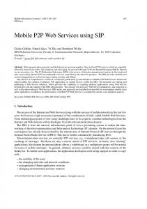
Figure 12: Effects of Vc on po , pf and pnc (η = 6µ, Vm = 1/η 2 ; solid: λo = 80µ; dashed: λo = 60µ) the previously proposed channel assignment schemes [23] (note that these schemes do not support the concept of PR and TR reservations): The first-in-first-out (FIFO) scheme: In this scheme, if the new IMS/access network does not have any free channel, the handoff sessions wait in a queue before the UE moves out of the handoff area. The time that a UE moves across the handoff area is referred to as the degradation interval. This scheme selects the next handoff session to serve in the FIFO basis. The measured-based priority scheme (MBPS): This scheme is similar to the FIFO scheme except for the queueing policy. MBPS uses a nonpreemptive dynamic priority policy. The priorities are defined by the power level that the UE receives from the new IMS/access network. A released channel is assigned to the queued handoff session with the highest priority. Figure 13 presents the comparison results between FIFO, MBPS and our scheme where µ = 1/3 min, η = 1/30 min, Vc = 1/µ2 , Vm = 1/η 2 , and the mean degradation interval is 18 sec. Since the TR session replacement policies do not have significant impacts, we only consider the random replacement policy in Figure 13. Figure 13(a) indicates that p o for our scheme is smaller than those for FIFO and MBPS. Figure 13(b) illustrates that FIFO and MBPS outperform our scheme in terms of pf . This is because FIFO and MBPS give high priority to handoff sessions. Figure 13(c) shows that p nc for FIFO, MBPS and our reservation 31
40 35 30 25 20 15 10 5 0
...�•. � : FIFO ....?.....?. . . . .�•.. • : MBPS .......?. ? : our scheme .�•....?....? . ...?.. ......?.. . • � . .? .. .. ....?. • � .........?. ? ..... ....?. ...�•..?... ...?. .?..... . . . .�• ....?.. ....?... . . . . ...�•...? ......?.. �•?...?. 40
50
60
70
λo (unit: µ) (a) po (%)
80
40
� : FIFO ...?. ..?. 35 • : MBPS ..?.?.. . ? : our scheme ?... . 30 .?.. ..?. . . ..? 25 .?. ?.. . . . 20 .?. ?.. .?... .. 15 ..?. . . ? ... 10 ..?. . ? . .... ?.. ............•�...... .•� 5 ..?.... ........•�.... •� . . . . � . • . . . . . . ? . . ?........•�.........•�.......•� 0 •�.. 40 50 60 70 80 λo (unit: µ) (b) pf (%)
40 35 30 25 20 15 10 5 0
.•�?. .?... � : FIFO ?... . . � • . .? • : MBPS .?.. ? : our scheme..•�?.... .. ....? ..?. � • . . ..? ..?. ... � • ? . .. ..?. ..•�.?.. .?. .?.. ...•�?... ... .....?. . . . ? . . .•�.. .......?. •�?.....?. 40
50
60
70
80
λo (unit: µ) (c) pnc (%)
Figure 13: Comparison between FIFO, MBPS and our scheme (µ = 1/3 min, η = 1/30 min, Vc = 1/µ2 , Vm = 1/η 2 , the mean degradation interval is 18 sec.) scheme are almost identical. We observe the same results under different µ and η values. Note that, we do not implement the waiting queue mechanism in our reservation scheme. This is due to the heterogeneity of the underlying access networks in the IMS interworking environment, and it is complicated to maintain waiting queues for handoff sessions. If the waiting queue approach is also considered, the pf in our scheme can be further improved, and our scheme will perform better than FIFO and MBPS with respect to p nc .
7
Conclusion
This paper proposed a mobile QoS framework for heterogeneous IMS interworking. To reduce the handoff disruption time, this framework supports the IMS mobility based on the concept of SIP multicast. In our approach, the mobility of a UE is modeled as a transition in the multicast group membership. To overcome mobility impact on service guarantees, UEs need to make QoS resource reservations in advance at neighboring IMS networks, where they may visit during the lifetime of the ongoing sessions. These locations become the leaves of the multicast tree in our approach. To obtain more efficient use of the scarce wireless bandwidth, our approach allows UEs to temporarily exploit the inactive bandwidths reserved by other UEs in the current IMS/access network. With the concept of dynamic shifting of the multicast group’s members, the flow of actual data packets can be switched to the new route as quickly as possible. Even though this
32
method requires a lot more background processing and consumption of bandwidth on wired links, we can eliminate the need for re-routing the data path during handoffs among IMS networks. We developed an analytic model for our proposed resource reservation scheme. This analytic model is different from the existing mobile network handoff models due to the introduction of PR and TR besides the traditional CR reservation. The analytic approach was validated against the simulation model. Based on the simulation experiments, we investigated the p o , pf and pnc performance of the resource reservation algorithm. Our study indicated the following. • Different TR session replacement policies have similar po , pf and pnc performance. • As the new session arrival rate λo increases, po , pf and pnc increase accordingly. • po and pf decrease as the UE mobility rate η increases. However, pnc increases as η increases. • po and pf increase as the variance Vm of IMS residence times increases, and pnc decreases as Vm increases. • For Vm ≤ 1/η 2 , po , pf and pnc are insensitive to Vm , and are only affected by the UE mobility η; for Vm � 1/η 2 , po , pf and pnc are insensitive to the UE mobility η. • All po , pf and pnc probabilities decrease as the variance Vc of session holding times increases. • po , pf and pnc are not affected by the changes of λo and Vc when Vc � 1/µ2 . • We compared our reservation scheme with the previously proposed channel assignment schemes “FIFO” and “MBPS”. The results showed that our scheme yields p nc performance comparable to that of FIFO and MBPS.
Acknowledgment We would like to thank the anonymous reviewers. Their valuable comments have significantly enhanced the quality of this paper.
References [1] 3GPP. 3rd Generation Partnership Project; Technical Specification Group Core Network and Terminals; Policy Control over Go Interface. Technical Specification 3G TS 29.207 version 6.5.0 (2005-09), 2005.
33
[2] 3GPP. 3rd Generation Partnership Project; Technical Specification Group Core Network and Terminals; Policy Control over Gq Interface. Technical Specification 3G TS 29.209 version 6.5.0 (2006-06), 2006. [3] Chlamtac, I., Fang, Y., and Zeng, H. Call Blocking Analysis for PCS Networks under General Cell Residence Time. IEEE Wireless Communications and Networking Conference (WCNC), New Orleans, September 1999. [4] Das, S. K., Lee, E., Basu, K., Kakani, N., and Sen, S. K. Performance Optimization of VoIP Calls over Wireless Links Using H.323 Protocol. IEEE Transactions on Computers, 52(6):742–752, June 2003. [5] Fang, Y. and Chlamtac, I. Teletraffic Analysis and Mobility Modeling for PCS Networks. IEEE Transactions on Communications, 47(7):1062–1072, July 1999. [6] Fang, Y., Chlamtac, I., and Fei, H.-B. Analytical Results for Optimal Choice of Location Update Interval for Mobility Database Failure Restoration in PCS networks. IEEE Transactions on Parallel and Distributed Systems, 11(6):615–624, June 2000. [7] Fantacci, R. Performance Evaluation of Prioritized Handoff Schemes in Mobile Cellular Networks. IEEE Transactions on Vehicular Technology, 49(2):485–493, March 2000. [8] Gross, D. and Harris, C.M. Fundamentals of Queueing Theory, 3rd Ed. John Wiley & Sons, 1998. [9] Hong, D. and Rappaport, S.S. Traffic Model and Performance Analysis for Cellular Mobile Radio Telephone Systems with Prioritized and Nonprioritized Handoff Procedures. IEEE Transactions on Vehicular Technology, 35(3):77–92, August 1986. [10] Hong, D., and Rappaport, S.S. Priority Oriented Channel Access for Cellular Systems Serving Vehicular and Portable Radio Telephones. IEE PROCEEDINGS-I, 136(5):339–346, 1989. [11] Huang, N.-F. and Chen, W.-E. RSVP Extensions for Real-Time Services in Hierarchical Mobile IPv6. Mobile Networks and Applications, 8(6):625–634, December 2003. [12] Hung, H.-N., Lee, P.-C., Lin, Y.-B., and Peng, N.-F. Modeling Channel Assignment of Small-Scale Cellular Networks. IEEE Transactions on Wireless Communications, 4(2):646–652, March 2005. [13] IETF. SIP: Session Initiation Protocol. IETF RFC 3261, June 2002. [14] IETF. Fast Handovers for Mobile IPv6. IETF RFC 4068, July 2005. [15] Jeon, W.S. and Jeong, D.G. Call Admission Control for CDMA Mobile Communications Systems Supporting Multimedia Services. IEEE Transactions on Wireless Communications, 1(4):649–659, October 2002. [16] Kelly, F.P. Reversibility and Stochastic Networks. John Wiley & Sons, 1979. [17] Kim, D.K. and Sung, D.K. Traffic Management in a Multicode CDMA System Supporting Soft Handoffs. IEEE Transactions on Vehicular Technology, 51(1):52–62, January 2002. [18] Li, B., Li, L., Li, B., and Cao, X.-R. On Handoff Performance for an Integrated Voice/Data Cellular System. ACM/Kluwer Wireless Networks, 9(4):393–402, July 2003. [19] Lin, Y.-B. Performance Modeling for Mobile Telephone Networks. IEEE Network, 11(6):63–68, November/December 1997.
34
[20] Lin, Y.-B. Reducing Location Update Cost in a PCS Network. IEEE/ACM Transactions on Networking, 5(1), 1997. [21] Lin, Y.-B. and Mak, V. K. Eliminating the Boundary Effect of a Large-Scale Personal Communication Service Network Simulation. ACM Transactions on Modeling and Computer Simulation, 4(2):165– 190, 1994. [22] Lin, Y.-B., Huang, Y.-R., Pang, A.-C., and Chlamtac, I. All-IP Approach for UMTS Third Generation Mobile Networks. IEEE Network, 5(16):8–19, January 2002. [23] Lin, Y.-B., Mohan, S., and Noerpel, A. Queueing Priority Channel Assignment Strategies for Handoff and Initial Access for a PCS Network. IEEE Transactions on Vehicular Technology, 43(3):704–712, 1994. [24] Orlik, P. V. and Rappaport, S. S. On the Handoff Arrival Process in Cellular Communications. ACM/Baltzer Wireless Networks, 7:147–157, March/April 2001. [25] Peha, J. M. and Sutivong, A. Admission Control Algorithms for Cellular Systems. ACM/Baltzer Wireless Networks, 7:117–125, March/April 2001. [26] Poikselka, M., Mayer, G., Khartabil, H., and Niemi, A. The IMS: IP Multimedia Concepts and Services, 2nd ed. John Wiley & Sons Ltd, 2006. [27] Ross, S.M. Stochastic Processes, 2nd ed. John Wiley, New York, 1996. [28] Schulzrinne, H. and Wedlund, E. Application-Layer Mobility using SIP. ACM SIGMOBILE Mobile Computing and Communications Review, 4(3):47–57, July 2000. [29] Snoeren, A. C. and Balakrishnan, H. An End-to-End Approach to Host Mobility. ACM/IEEE International Conference on Mobile Computing and Networking, pages 155–166, August 2000. [30] Soh, W.-S. and Kim, H. S. QoS Provisioning in Cellular Networks Based on Mobility Prediction Techniques. IEEE Communications Magazine, 41(1):86–92, January 2003. [31] Wu, W., Banerjee, N., Basu, K., and Das, S. K. SIP-based Vertical Handoff between WWANs and WLANs. IEEE Wireless Communications, 12(3):66–72, June 2005. [32] Xhafa, A. and Tonguz, O. K. Dynamic Priority Queueing of Handoff Requests in PCS. IEEE International Conference on Communications, 2:341–345, 2001. [33] Yang, X. and Agarwal, A. Multicast Mobility in SIP Layer. IEEE Vehicular Technology Conference, 2004. [34] Zeng, Q.-A. and Agrawal, D.P. Modeling and Efficient Handling of Handoffs in Integrated Wireless Mobile Networks. IEEE Transactions on Vehicular Technology, 51(6):1469–1478, November 2002.
35