Nigerian Journal of Technology (NIJOTECH) Vol. 34 No. 4, October, 2015, pp. 750 – 760 Copyright© Faculty of Engineering, University of Nigeria, Nsukka, ISSN: 0331-8443 www.nijotech.com
http://dx.doi.org/10.4314/njt.v34i4.12
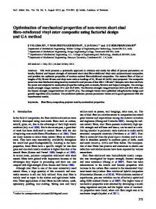
TENSILE AND HARDNESS PROPERTY EVALUATION OF KAOLINKAOLIN- SISAL FIBREFIBRE- EPOXY COMPOSITE I. M. Dagwa1; K. K Adama2,*; A. Gadu3 and N. O. Alu4 1DEPARTMENT OF MECHANICAL ENGINEERING, UNIVERSITY OF ABUJA, P.M.B 117, ABUJA, FCT, NIGERIA. 2, 4 PHYSICS ADVANCED LABORATORY, SHEDA SCIENCE AND TECHNOLOGY COMPLEX, SHEDA, ABUJA FCT NIGERIA 3NUCLEAR TECHNOLOGY CENTRE, POLYMER
LABORATORY, ATOMIC ENERGY COMMISSION, SHEDA, ABUJA FCT, NIGERIA addresses es::
[email protected], 2
[email protected], 3
[email protected] Email address es 4
[email protected] 1
ABSTRACT
In this work, the tensile and hardness properties of Kaolinfibre-- epoxy composite were evaluated using Kaolin- sisal fibre standard methods. Epoxy type 3354A with its hardener was mixed in the ratio 2:1. Calcined kaolin particle with average size of 35µm and 33-4mm sisal fibre were added to the epoxy matrix during the composite manufacture in a proportion of: 60/40 wt %, 60/30/10 wt %, 60/20/20 wt %, 60/10/30 wt % for matrix, fibre fibre and Kaolin respectively. The green mixtures were poured into aluminum mould and left for 24 hrs to cure. The results showed that the addition of kaolin and sisal fibre affected mechanical properties of the epoxy resin. The maximum strain ach specimen after tensile tests were as follows: 12% for specimen A; 12% for specimen B; 3.9% for observed for eeach specimen C; 11.5% for specimen D and 6% for specimen E. The Shore D hardness values were as follows: 79.1 for 42.82 specimen A ((control); control); 55.68 for specimen B; 42. 82 for specimen C; 78.7 for specimen D and 81.34 for specimen E. The hardness values was reduced from 55.68 to 42.83 and increased to 81.34. Specifically, the tensile and hardness properties increased proportionately with the fibre quantity and inversely proportional proportional to the kaolin content. These fibre--matrix matrix--particulate interfacial adhesions. are attributed to the level of bonding strengths between the fibre Keywords: Epoxy Kaolin-Sisal fiber composite; Tensile and hardness properties; XRD; Shore D hardness; Calcinations 1. INTRODUCTION Currently, there has been a high volume of research focus on developing environmentally friendly, sustainable and reliable composite materials [1-7]. When the right proportion of constituent materials are mixed in the most suitable matrix or resin, it will lead to the production of composite with better properties when compared to the materials’ initial properties. Some of the engineering and economic benefits derivable from this effort include: energy savings, light weight, cleaner environment, low cost, high specific strength and biodegradability. Some of the areas of structural application of these composites are in automobile, aerospace and aircraft parts due to reduction in weight [8, 9]. In order to enhance the properties of the composites formed, fiber modification or pretreatment using both physical and chemical methods are paramount. This method of *Corresponding author, Tel: +234+234-812812-176176-6080
fiber modification or pretreatment includes mercerization, isocyanate treatment, acrylation, permanganate treatment, acetylation, silane treatment and peroxide treatment [10-12]. Several studies on the use of natural fibers in reinforcing plastics and composites have been reported [13–15]. Generally, it is acknowledged that the efficiency of any fiberreinforced composite is dependent on interface between the matrix and the fiber, hence the composites’ ability to transfer the stress from the matrix to the fiber. This property enhances and determines the mechanical properties of such composite formed. Hybridization gives room for flexibility in materials design thereby providing opportunities for tailoring material properties in certain areas to meet specific requirements. In order to improve upon the strength and absorptivity resistances of natural- fiber incorporated composites,
TENSILE AND HARDNESS PROPERTY EVALUATION OF KAOLIN- SISAL FIBRE- EPOXY COMPOSITE
several studies [16-20] have shown the hybridization of these fibers in composite development. Studies reveal that the tensile strength and modulus of hybrid glass/flax/polypropylene composite was a function of the composition ratio of the glass to flax [21-22]. Similarly, addition of coupling agents was found to improve the flexural and tensile properties of most composites [22-26]. Kaolin is an inert inorganic and predominantly amorphous substance which is sparingly soluble in water. Calcined kaolin consists mainly of quartz which is normally crystalline silica [27]. Kaolin clay can be chemically described as a group of stacked anhydrous aluminum silicates composed of approximately 45% silica (SiO2), 37% alumina (Al2O3) and minor naturally occurring trace impurities. Calcination process in kaolin modification enhances the properties of the final material obtained. The calcination of kaolin removes the crystalline bound water of hydration which is usually 14% by weight[28 - 30].The calcined kaolin can serve as a binding agent, filler, fixing agent, heat transfer agent, catalyst support and processing aid in a broad range of application [30]. The calcination process drives off water from the main constituent of kaolin which is kaolinite (Al2Si2O5(OH)4) thereby collapsing the material structure which gives rise to an amorphous aluminosilicate (Al2Si2O7) called metakaolinite, this process renders the kaolin non-plastic[30]. A typical composition of kaolin is presented in Table 1. The use of epoxy resin in composite studies is quite extensive [31-33]. Epoxies find application in metal coatings, electronic and electrical components, hightension electrical insulators, fibre-reinforced plastic/composite materials and structured adhesives [33]. However, polyesters, vinyl ester and other thermosetting resins can also be used for fiber reinforced composite materials. The choice of epoxy matrix in this study is due to its known and excellent adhesion, chemical and heat resistance, good/excellent mechanical properties and very good electrical insulating properties. Though they are more expensive than polyester resins and vinyl ester resins, they produce stronger and more temperatureresistant composite parts/materials.
I. M. Dagwa, et al
Composites are commonly produced by mixing fibers which serve as reinforcement agents with fillers in a polymeric resin as matrix. The role of fiber in the composite serves as a means of load transfer, and also, resists tensile/flexural loads [34-36]. To minimize the use of high energy based fibers, researchers [37-39] have adopted the use of hybridized fibers which can be a mixture of synthetic and natural fibers or a combination of natural fibers. The use of biodegradable materials is presently facing some inherent challenges [40-44], among which are: inadequate technical information on plants, variations in species, processing ability at industrial level, environmental effects due to humidity and temperature and influence of microbial organisms on the structural integrity of the composite formed [4547]. However, no studies exist on the hybridization of sisal fiber with calcined kaolin and epoxy matrix in composite fabrication. The use of sisal fiber only in the development of composite and as a means of reinforcement in composite polymer has been reported by many researchers [48-52]. In these studies, it was observed that cracking of the matrix resin, bridging and breakage of the fiber materials, fracture failure and fatigue wears were the prominent composite disintegration challenges encountered. In this work, our focus is to investigate the tensile and hardness properties of the short sisal fiber reinforced with kaolin particle filled epoxy matrix. 2. MATERIALS AND METHODS 2.1 Preparation of the Kaolin Raw Kaolin was sourced from a deposit in Alkaleri town, Bauchi State, Nigeria. The kaolin was sieved through a stack of sieves ranging in pore size (diameter) of 500µm to 35µm to obtain the finest particle size of 35µm. The finest particle size of the kaolin, 35µm sieve size was then placed in a stainless steel container and calcined in a Thermotech TIC4000E oven with temperature controller. The temperature of the oven was maintained at 700oC for six (6) hours during the calcination process to remove traces of moisture from the kaolin. The calcination was meant to remove the crystalline bound water of hydration which is usually 14% by weight[27 - 30].
Table 1: Chemical composition of Kaolin [20] Oxides Percentages%
SiO2 46.66
Nigerian Journal of Technology
FeO3 0.83
Al2O3 34.41
TiO2 1.20
CaO 0.96
MgO 0.34
Na2O 0.30
K2O 0.34
L.O.I 12.92
Vol. 34 No. 4, October 2015
751
TENSILE AND HARDNESS PROPERTY EVALUATION OF KAOLIN- SISAL FIBRE- EPOXY COMPOSITE
Figure 1: Chopped and treated Sisal Fibers During the calcination process, impurities in the kaolin were oxidized. Thereafter, the calcined kaolin was packaged in a sealed cellophane bag and kept in a desiccator. 2.2 Preparation and Treatment of the Sisal Fibre Alkaline (mercerization) treatment of the sisal fiber was undertaken [10-12]. A known weight of sodium hydroxide pellet (204g) was dissolved in 10 liters of distilled water and 900g of sisal fiber was thereafter soaked in the solution. Weight/weight percent of sodium hydroxide pellet and distilled water was used in the preparation of 2% NaOH solution. The solution was maintained at room temperature for 24hrs in an enclosure. The resulting fibers were thoroughly and severally washed in distilled water and left to dry at room temperature for 48hrs with the aid of an electric fan. Subsequently, the treated fibers were oven-dried at 100oC for 2days at 8hrs per day due to the high humidity of the period. Finally, the fibers were chopped to required sizes ranging from 2mm to 4mm with the aid of scissors and paper board cutter. Figure 1 shows the chopped and treated sisal fibers. 2.3 Matrix material The matrix material used was Epoxy type 3354A and its hardener. Epoxy type 3354A is a two component, 100% solid epoxy resin. The hardener used was a medium speed hardener with a pot life of 20 – 25min, set time of 3 – 4hrs and dry time of 8 – 10hrs.The epoxy resin and the hardener were of high analytical grade purchased from a vendor. 2.4 Composite Material Manufacture An aluminum mould prepared based on ASTM D638 for the tensile test specimen was used for producing the required composite specimens. Firstly, a mould releasing agent; polyvinyl acetate (PVA) was applied Nigerian Journal of Technology
I. M. Dagwa, et al
Figure 2: Sample A severally on the mould to fill-up any cavity noticed on the mould and to act as a mould releasing agent. This was then oven-dried at 70oC for 2hrs. Thereafter, the PVA was re-applied on the mould and left to dry at room temperature for 6hrs. In addition to the use of the PVA as mould releasing agent, RTV silicone sealant (ABRO 2000, U.S.A) which bonds, seals and insulates the mould was applied to fill noticed cavities on the mould and this was left to cure at room temperature for 24hrs. The procedure was repeated for subsequent composite specimens’ preparations.
2.4.1 Preparation of the Control Composite Specimens A calculated volume of epoxy resin and hardener in the ratio of 2:1 was used as ‘control’ for sample ‘A’ preparation. 146.66ml of epoxy resin was measured using a measuring cylinder and a MEHECO disposable syringe into a clean plastic container (bowl). Also, 73.34ml of the hardener was measured using another disposable syringe into the same plastic bowl. The mixture was gently but thoroughly stirred manually for 5minutes to create an even and homogeneous mixture and to minimize gas/air entrapment. The mixture was gradually but gently poured into two sets of moulds and left to cure for 24hrs at room condition. The specimens were evacuated from the mould and then prepared for characterization according to relevant standards. Sample sets A is shown in figure 2.
2.4.2 Preparation of samples Preparation of sample sets B, C, D and E represent different weight percents of the fiber material and the kaolin in the final composite samples. The percentage weight of epoxy resin in all four samples was kept constant while the percentage weight of both the fiber material and kaolin was varied appropriately as shown in Table 2. Vol. 34 No. 4, October 2015
752
TENSILE AND HARDNESS PROPERTY EVALUATION OF KAOLIN- SISAL FIBRE- EPOXY COMPOSITE
Table 2: Designation and detailed composition of the composites Designation
Composition
Sample A
Epoxy (60wt%) +Hardener (40 wt.%)
Sample B Sample C Sample D Sample E
Epoxy/ Hardener (60wt.%) + sisal fiber (40 wt.%) +kaolin (0wt% ) Epoxy/ Hardener (60wt.%) + sisal fiber (30 wt.%) +kaolin (10wt% ) Epoxy/ Hardener (60wt.%) + sisal fiber (20 wt.%) +kaolin (20wt% ) Epoxy/ Hardener (60wt.%) + sisal fiber (10 wt.%) +kaolin (30wt% )
In all sample preparations, 150.33ml of the matrix consisting of the epoxy and the hardener in the ratio of 2:1 respectively was measured and mixed in a plastic bowl into which30g, 60g, 90g and 120g respectively of the fiber material (sisal) and 90g, 60g and 30g respectively of the filler material (kaolin) was thoroughly mixed together for 10 minutes to ensure proper and even distribution of kaolin and fiber in the mixture phase. Afterward, the mould was gradually and gently filled-up with the composite until the cavity was completely filled with the composite material. This was left to cure for 24hrs at room temperature. Finally, the composite samples were evacuated from the mould after 24hrs and characterized accordingly. Figure 3 shows the composite samples.
I. M. Dagwa, et al
scan range (2θ) was from 10° to 100° with a step size (2θ) of 0.0670, scan step time (sec) of 59.6900 and using CuKα monochromatic radiations Kα1 and Kα2 of 1.54060Å and 1.54443Å respectively and K-beta of 1.39225Å. The wavelength, accelerating voltage and current were 1.54060Å, 40Kv and 30mA, respectively. The intensity of the rays was measured at Bragg’s 2θ angle from start angle of 10° to end angle of 100° and this was displayed as the scan diffractogram on a real time computer connected to the XRD system. The crystallinity and other parameters were determined from the x-ray diffraction analysis using the system’s softwares. 2.6 Mechanical Properties Tensile and hardness tests were conducted on the specimens using a TIRA test system and Zwick 3115 hardness test machine.
2.6.1 Tensile Test The Tensile test was done with a TIRA test 2810 universal test machine. Each specimen was set-out for test with a gauge length of 56 mm. Before the commencement of the test, the specimens; A’s, B’s, C’s, D’s and E’s were machined to size,13 x 7.50 mm,13 x 7.50 mm,13 x 9.00 mm,13 x 10 mm and 13 x 7.20 mm, respectively according to ASTM D3039 standard. The TIRA test 2810 system was set in tensile mode with a test speed of 1 mm/min and a strain-rate of 10 N/s. Each specimen was gripped at a gauge length of 56 mm. The test was conducted using ASTM D3039 standard with 85% End-Of-Test-Criterion.
2.6.2 Hardness Test
Figure 3: Composite Samples 2.5 Structural Analysis of the Calcined Filler Material (Kaolin) and Treated Fibre Material (Sisal) The structural analysis of the calcined kaolin and the treated sisal materials were conducted using a PANalytical XPERT-Pro MPD X-ray Diffractometer PW 3040/60 system [53-57]. Powdered sisal and kaolin samples weighing 5g were separately loaded into a cylindrical sample holder which was mounted on the XRD machine sample stage. Monochromatic radiation was allowed to strike the mounted samples after stage- spinning was enabled on the sample stage, for the required scanning time and 2θ angle[58-61]. The Nigerian Journal of Technology
The test, using Shore (Durometer) hardness method was done at 24°C and measurements were made on at least three different positions on the specimen, 10 mm apart. The indenter was vertical with respect to the specimen surface during test. The hardness tester’s contact surface was brought into contact with the specimen material without jolting. The test load used according to the Shore D hardness test was 50N and the hardness value was read off three seconds after the hardness tester contacted the specimen in accordance to ASTM D2240. 3. RESULTS AND DISCUSSION 3.1 Treatment of the Sisal Fiber The treatment process of the sisal fiber using mercerization led to an increase in the amount of amorphous cellulose and the removal of hydrogen Vol. 34 No. 4, October 2015
753
TENSILE AND HARDNESS PROPERTY EVALUATION OF KAOLIN- SISAL FIBRE- EPOXY COMPOSITE
bonding in the network structure [8, 9]. Since the natural fiber had hydroxyl groups from cellulose and lignin, hence, amenable to modification. The surface tension and polarity of the fiber surface was modified through the process resulting in cleaner fiber surface that had been chemically modified, stoppage of moisture absorption process and increase in fiber surface roughness [10-12]. Similarly, adhesion between fiber surface and polymer matrix was improved as well as improvement in fiber strength resulting in enhanced mechanical properties [13, 14, 16, and 18].
Figure 4: XRD diffractogram of calcined kaolin
Figure 5: XRD diffractogram of treated sisal fibers 3.2 XX-ray Diffractometry Analysis The XRD profile of the calcined kaolin samples identified quartz as the main constituent of the sample with a chemical formula of SiO2. The quartz was identified variously as low synthetic quartz, amorphous-SiO2 and low-grade quartz with scores of 53%, 40% and 42% respectively on the International Centre for Diffraction Data (ICDD) database [53-56]. The profile exhibited well resolved and intense peaks at 2θ positions 20.8283°, 25.2718°, 26.6019°, 48.0066° and 50.1323°. These peaks identified the compound as mainly quartz (SiO2) with the highest peak position occurring at 26.6019° corresponding to a Height of 1871.00 (cts) [57]. The crystallographic Nigerian Journal of Technology
I. M. Dagwa, et al
parameters showed a hexagonal single crystal system. It was observed to be an inorganic mineral which can serve as a cement and hydration product [58-61]. The XRD diffractogram of the calcined kaolin is shown in Figure 4. The XRD analysis of the sisal fiber indicated three prominent peaks at 2θ positions of 14.9231°, 16.1714° and 22.7477° with the highest peak height occurring at a height of 6625.35cts. The constituent compound of the sisal fiber was identified as Sodium Calcium Aluminum Boron Oxide Hydrate with a chemical formula of B11.7Al2Ca1.32Na0.12O21.93.5.4H2O and empirical formula of Al2B11.7Ca1.32H10.8Na0.12O27.33. It had a scale factor of 0.974, a score on the ICDD database of 57 [53-57].Each of the peaks corresponds to the identified constituent compound in the sisal fiber but with varying compositions/ (degrees). The crystallographic crystal system parameter was unmatched indicating a purely amorphous chemically treated material [58-61]. The XRD diffractogram of the treated sisal fiber is shown in Figure 5. 3.3Tensile 3.3Tensile strength From the tensile test, plots were generated for loadcrosshead position and their corresponding stressstrain relationship. For each specimen, multiple plots were obtained corresponding with the three number of samples tested and designated as 1, 2, 3 respectively. The average of each plot was produced and represented as A, B, C, D, and E together with the multiples as shown in Figures 6 - 10. Figures 6 – 10 show the stress-strain curves for the different specimens. For the ‘control sample A’, the stress-strain curve was not perfectly linear. The maximum strain recorded was 12 %. For composite specimen B, there was a linear relationship between the stress and strain from 0 to 4.3%, thereafter a steep increase which had a linear relationship was observed from 4.3% to a maximum strain of 12%. However, for specimen C, there was a linear relationship between the stress and strain from 0 to 3.7%. Thereafter, a steep increase that had linear relationship from 3.7% to 3.8 % (maximum strain) was observed before failure because of the high volume fraction of fiber in specimen C, which suggests that there was no good adhesion between kaolin and fiber, leading to the sudden (3.8%) failure of the specimen. Specimen D, had linear relationship from 2- 11.5 %. This composite represents equal amount (by weight) of sisal fibre and kaolin powder. Vol. 34 No. 4, October 2015
754
TENSILE AND HARDNESS PROPERTY EVALUATION OF KAOLIN- SISAL FIBRE- EPOXY COMPOSITE
I. M. Dagwa, et al
(a)
(b)
Figure 6: Load versus crosshead and its corresponding stress-strain for sample set A
(a)
(b) Figure 7: Load versus crosshead and its corresponding stress-strain for sample set B Nigerian Journal of Technology
Vol. 34 No. 4, October 2015
755
TENSILE AND HARDNESS PROPERTY EVALUATION OF KAOLIN- SISAL FIBRE- EPOXY COMPOSITE
I. M. Dagwa, et al
(a)
(b)
Figure 8: Load versus crosshead and its corresponding stress-strain for sample set C
(a)
(b)
Figure 9: Load versus crosshead and its corresponding stress-strain for sample set D Nigerian Journal of Technology
Vol. 34 No. 4, October 2015
756
TENSILE AND HARDNESS PROPERTY EVALUATION OF KAOLIN- SISAL FIBRE- EPOXY COMPOSITE
I. M. Dagwa, et al
(a)
(b)
Figure 10: Load versus crosshead and its corresponding stress-strain for sample set E For specimen E, the maximum strain attained was 6% at a lower stress (2.4N/mm2). Subjecting the specimens to the same strain rate, it was observed that specimen C had the least strain (3.8%). Composite materials with higher stress-strain values tend to show appreciable elongation before failure. Hence, the order of elongation before failure of the specimens was: A=B>D>E>C. From the bar chart analysis of the ultimate tensile strength (UTS) shown in Figure11, the maximum stress was in the order A>B>D>C>E, it was observed that there was a gradual reduction in UTS from sample B to E occasioned by the increase in Kaolin and reduction in sisal fiber content. A similar study using another member of the clay family confirms that more addition of red mud decreases the tensile strength value of sisal/polymer composite [22]. This was due to the chemical reaction at the interface between the filler particles and the matrix getting too weak to transfer the tensile stress [22-24]. However, as the percentage fiber increased, the UTS also increased correspondingly. It can be inferred that the presence Nigerian Journal of Technology
of kaolin particles might have caused some form of obstruction to load transfer from the matrix to the fibers. It has been reported [24] that as fiber quantity is increased in a composite, there is a corresponding increase in its tensile strength due to improved interfacial adhesion between the fiber and the matrix. In this study, a similar behavior was observed. 3.4 Hardness From Figure 12, it was observed that the Shore D hardness of the matrix composite reduced from 55.68 (40wt% sisal, 0wt% kaolin (Sample B)) to 42.82 (30wt% sisal, 10wt% kaolin (Sample C)) and thereafter increased to a maximum of 81.34 (10wt% sisal, 30wt% kaolin (Sample E)). A trend observed was such that the more kaolin in the composite, the greater the hardness values of the final composite formed. Therefore, the increase in hardness was due to the improvement in the bonding strength between the kaolin particles and the matrix. This is agreement with the work done by Manasa et.al [62].
Vol. 34 No. 4, October 2015
757
TENSILE AND HARDNESS PROPERTY EVALUATION OF KAOLIN- SISAL FIBRE- EPOXY COMPOSITE
I. M. Dagwa, et al
6. REFERENCES 1.
2.
3.
Figure 11: Ultimate tensile strength (UTS) of the composite fabricated.
4.
Thermogravimetric Study: Poly ethylene/Orange Peels Ash Composite, Lambert Academic Press, 2011. 5.
6.
7.
Figure 12: Shore D versus Sample composition
4. CONCLUSION From this study, the following conclusions were drawn: i. The tensile strength increased with increase in sisal fiber loading. ii. Increase in kaolin loading yielded improvement in hardness. This was attributed to the presence of quartz (SiO2), which is the major constituent of kaolin. However, the tensile strength of the composite decreased with increase in kaolin due to poor adhesion between the kaolin and matrix for effective load transfer to the sisal fibre. iii. The maximum strain observed for each specimen were as follows: 12% for specimen A; 12% for specimen B; 3.9% for specimen C; 11.5% for specimen D and 6% for specimen E. Hence, the order of elongation before failure of the specimens was: A=B>D>E>C which shows that increment in kaolin reduces the strain values. 5. ACKNOWLEDGEMENT ACKNOWLEDGEMENT The authors of this work appreciate the kind assistance granted by SHESTCO, Abuja, Nigeria. Nigerian Journal of Technology
Mohanty, A.K., Misra, M., Drzal, L.T. “Surface Modifications of Natural Fibers and Performance of the Resulting Biocomposites: An Overview”, Composite Interfaces, Vol. 8, Number 3, 2001, pp 313-343. Zhong, J.B, Lv, J., Wei; C. “Mechanical Properties of Sisal Fibre Reinforced Urea-Formaldehyde resin Composites”, ExPRESS Polymer Letters, Vol.1, Number 10, 2007, pp 681-687. Joseph K., Thomas S., Paul A. “Effect of Surface Treatments on the Electrical Properties of Low Density Poly Ethylene Composites Reinforced with Short Sisal Fibers”, Composites Science and Technology, Vol. 57, 1997, pp 67-79. Aigbodion, V.S., Atuanya, C.U., and Juku, G.S. Ishidi, E.Y., Lolawale, E.G., Sunmonu, K.O., Yakubu, M.K., Adamu I.K and Obele, C.M. “Study of PhysioMechanical Properties of High Density Poly Ethylene (HDPE) Palm Kernel Nut Shell (Elaeis guineasis) Composites”, Journal of Emerging Trends in Engineering and Applied Sciences, Vol. 2, Number 6, 2011, pp 1073-1078. Kasama, J. and Nitinat, S. “Effect of Glass Fiber Hybridization on Properties of Sisal FiberPolypropylene Composites”, Composites: Part B, Vol. 40, 2009, pp 623-627. Velmurugan, R. and Manikandan, V. “Mechanical Properties of Palmyra/Glass Fiber Hybrid Composites”, Composites: Part A, Vol. 38, 2007, pp 2216-2226.
8.
Mallick, P. K. Fiber-Reinforced Composites. In: Materials, Manufacturing and Design. New York, NY: Marcel Dekker, Inc., 1989.
9.
Karnani R., Krishnan M., Narayan R. “BiofiberReinforced Polypropylene Composites” Polymer Engineering and Science, Vol. 37, Number 2, 1997, pp 476-83.
10. Bledzki A. K., Reihmane S., Gassan J. “Properties and Modification Methods for Vegetable Fibers for Natural Fiber Composites”, Journal of Applied Polymer Science, Vol. 59, Number 8, 1996, pp 132936. 11. Njoku R.E; Ofili I; Agbiogwu D.O and Agu C.V. “Effect of Alkali Treatment and Fiber Content Variation on the Tensile Properties of Coir Fiber Reinforced Cashew Nut Shell Liquid (CNSL) Composite”, Nigerian Journal of Technology, Vol. 31, Number 2, 2012, pp 107 – 110. 12. Valadez-Gonzalez, J. M., Cervantes-U. C., Olayo R., Herrera-Franco P. J. “Effect of Fiber Surface Treatment on the Fiber –Matrix Bond Strength of Natural Fiber Reinforced Composites”, Composites Part B Engineering, Vol. 30, Number 30, 1999, pp 309 – 320.
Vol. 34 No. 4, October 2015
758
TENSILE AND HARDNESS PROPERTY EVALUATION OF KAOLIN- SISAL FIBRE- EPOXY COMPOSITE 13. Chand N., Hashmi S. A. R. “Mechanical Properties of Sisal Fiber at Elevated Temperatures”, Journal of Materials Science, Vol. 28, Number 4, 1993, pp 67248. 14. Devi U., Bhagawan S. S., Thomas S. “Mechanical Properties of Pineapple Leaf Fiber-Reinforced Polyester Composites”, Journal of Applied Polymer Science, Vol. 63, Number 3, 1997, pp 1739 – 48. 15. Njoku R.E; Obayi C.S; Nnamchi P.S “Hybrid Effect on the Mechanical Properties of Sisal Fiber and E-glass Fiber Reinforced Polyester Composites”, Nigerian Journal of Technology, Vol. 30, Number 3, 2011. 16. Panathapulakkal S., Sain M. “Injection-Molded Short Hemp Fiber/Glass Reinforced Polypropylene Hybrid Composites – Mechanical, Water Absorption and Thermal Properties” Journal Applied Polymer Science, Vol. 103, Number 5, 2007, pp 2432 – 2441. 17. Rozman H. D., Tay G. S., Kumar R. N., Abusamah A., Ismail H, Mohd Ishak Z. A. [2001]. “Polypropylene-Oil Palm Empty Fruit Bunch-Glass Fiber Hybrid Composites: A Preliminary Study on the Flexural and Tensile Properties”, European Polymer Journal, Vol. 37, 2001, pp 1283-91. 18. Arbelaiz A., Fernandez B., Canter G., Liano-Ponte R., Valea A., Mondragon I. “Mechanical Properties of Flax Fiber/Polypropylene Composites: Influence of Fiber/Matrix Modification and Glass Fiber Hybridization” Composites Part A: Applied Science and Manufacturing, Vol. 36, Number 3, 2005, pp 1637- 44. 19. Sain M., Suhara P., Law S., Bouilloux A. “Interface Modification and Mechanical Properties of Natural Fiber-Polyolefin Composites Products” Journal of Reinforced Plastics Composites, Vol. 24, Number 2, 2005, pp 121-30. 20. Al-Asade Jabber Z., Al-Murshdy Mohammed J. “An Investigation of Kaolin Influences on Mechanical Properties of Unsaturated Polyester Composites”, Journal of Kerbala University, Vol. 6, Number 1, 2008, pp 242 - 252. 21. Kasama Jarukumjorn, Nitinat Suppakarn. “Effect of Glass Fiber Hybridization on Properties of Sisal Fiber-Polypropylene Composites”, Composites Part B: Engineering , Vol. 40, 2009, pp 623-627 22. Pradu Arumuga, V., Manikandau, V., Uthayakumar, M., Kalirasu, S. “Investigation on the mechanical properties of red mud filled sisal and banana fiber reinforced polyester composites”, Material Physics and Mechanics, Vol. 15, 2012, pp 173 – 179. 23. Joseph P.V., Joseph K., Thomas S. “Short Sisal Fiber Reinforced Polypropylene Composites: The Role of Interface Modification on Ultimate Tensile Properties”, Composite Interfaces, Vol. 9, 2002, pp 171-205. 24. Fung K. L., Xing X. S., Li R. K. Y., Tjong S. C., Mai Y. W. “An Investigation on the Processing of Sisal Fiber Nigerian Journal of Technology
I. M. Dagwa, et al
Reinforced Polypropylene Composites”, Composites Science and Technology, Vol. 63, 2003, pp 12251258. 25. De Rodriguez N. L. G., Thielemans W., Dufresne A. “Sisal Cellulose Whiskers Reinforced Polyvinyl Acetate Nanocomposites”, Cellulose, Vol. 13, 2006, pp 261-270. 26. Alvarez V., Vazquez A., Bernard C. “Effect of Microstructure on the Tensile and Fracture Properties of Sisal Fiber/Starch-Based Composites”, Journal of Composite Materials, Vol. 40, 2006, pp 2135. 27. Emofuriefa, W.O., Kayode, A.A., and Coker, S.A. “Mineralogy, Geochemistry and Econonic Evaluation of Kaolin Deposits near Ubulu-Uku, Awo-Omana and Buan in Southern Nigeria”, Journal of Mining and Geology, Vol. 28, Number 2, 1992, pp 211-220. 28. Lucas, A., Uguina, M.A., Covian, I., Rodriguez, L. “Synthesis of 13X Zeolite from Calcium Kaolin and Sodium Silicate for use in Detergents”, Industrial Engineering and Chemical Research, Vol. 3, Number 9, 1992, pp 2134 - 2146. 29. Zheng, S., Shuhong, S., Zhang, Z., Gao, X., and Xu, X. “Effects of Properties of Calcined Microspheres of Kaolin on the Formation of NaY Zeolite”, Bulletin of the Catalysis Society of India, Vol. 4, 2005, pp 12-17. 30. Zones, S.I., Davis, M.E. “Zeolite Materials: Recent Discoveries and Future Prospects”, Current Opinion in Solid State and Material Science, Vol. 1, 1996, pp 107 - 200. 31. Thomas, J.M., and Thomas, W.J. Principles and Practice of Heterogeneous catalysis, 2nd Edition, Wiley-VCH, Weinheim, U.S.A., 1997. Tanaka. Epoxy Resins Chemistry and Technology, Chapter 2: Synthesis and Characterization of Epoxides, Marcel Dekker, U.S.A,
32. Yoshio
pp.54-63, 1998. 33. Hammerton L., Rebbeca D. Recent Developments in Epoxy Resins, RAPRA Review Reports, p 8, 1997. 34. Bledzki, A.K., Reihmate, S., Gassau, J. “Properties and Modification Methods for Vegetable Fiber for Natural Fiber Composites”, Journal of Applied Polymer Science, Vol. 59, Number 8, 1996, pp 1329-36. 35. Herrena-Franco, P.J. Valadez-Gonzalez, A. “A Study of the Mechanical Properties of Short Natural-Fiber Reinforced Composites”, Composites B, Vol. 36, 2005, pp 597-608. 36. Donald R. Askeland. The Science and Engineering of Materials, Alternate Edition, PWS Publishers, U.S.A, 1985. 37. Dutra, R.C.L. Soares, B.G. Campos, E.A. Silva, J.L.G. “Hybrid Composites Based on Polypropylene and Carbon Fiber and Epoxy Matrix”, Polymer Composites, Vol. 41, 2000, pp 3841-3849. 38. Wan, Y.Z., Wang, Y.L., He, F. Huanh, Y., Jiang, H.J. “Mechanical Performance of Hybrid Bismaleimide Composites Reinforced with three Dimensional
Vol. 34 No. 4, October 2015
759
TENSILE AND HARDNESS PROPERTY EVALUATION OF KAOLIN- SISAL FIBRE- EPOXY COMPOSITE
39.
40.
41.
42.
43.
44.
45.
46.
47.
Braided Carbon and Kevlar Fabrics”, Composites: Part A, Vol. 38, 2007, pp 495-504. Yong, L., Qinglin, W., Fei, Y., Yanjun, X. “Preparation and Properties of Recycled HDPE/Natural Fiber Composites” Composites: Part A, Vol. 38, 2007, pp 1664-1674. Pal S., Mukhopadhayay D., Sanyal S., Mukherjea R. “Studies on Process Variables for Natural Fiber Composites - Effect of PEAP as Interfacial Agent”, Journal of Applied Polymer Science, Vol. 35, 1988, 973-985. Corbiere-Nicollier T., Laban B.G., Lundquist L., Leterrier Y., Manson J.A.E, Jolliet O. “Life Cycle Assessment of Bio-Fiber replacing Glass Fibers as Reinforcement in Plastics Conservation” Recycling, Vol. 33, 2001, pp 267-287. Sreekala M.S., Kumaran M.G., Geethakumariamma M.L and Thomas S. “Environmental Effects in Oil Palm Fiber Reinforced Phenol Formaldehyde Composites: Studies on Thermal, Biological, Moisture, and High Energy Radiation Effects”, Advanced Composite Materials, Vol.13, 2004, pp 171-197. John, M.J., Francis B., Vanghese K.T. and Thomas S. “Effect of Chemical Modification on Properties of Hybrid Fiber Bio-Composites”, Composites: Part A: Applied Science and Manufacturing, Vol 39, Vol. 2008, pp 352-363. Enetanya A.N. “Environmental Effects on Tensile Strength and other Mechanical Properties of Hand Lay-Up Panels”, Nigerian Journal of Technology, Vol. 22, Number 1, 2003, pp 64 – 70. Valadez-Gonzalez, J.M., Cervantes Uc, Olayo R., and Herrera-Franco P.J. “Effect of Fiber Surface Treatment on the Fiber Matrix Bond Strength of Natural Fiber Reinforced Composites”, Composites Part B: Engineering, Vol. 30, Number 3, 1999, pp 309-320. Herrera-Franco P.J., and Valadez-Gonzalez, J.M. “A study of the Mechanical Properties of Short Natural Fiber Reinforced Composites”, Composites. Part B, Vol. 36, 2005, pp 597-608. Luo S. and Netravali A.N. “Interfacial and Mechanical Properties of Environment-Friendly ‘Green’ Composites made from Pineapple Fibers and Poly (Hydroxybutyrate-co-valerate) Resin”, Composite Science and Technology, Vol. 8, Number 4, 1999, pp 207 – 229.
48. Sikarwar Rahul S., Raman Velmurugan., Velmuri Madhu. “Experimental and Analytical Study of High Velocity Impact on Kevlar/Epoxy Composite Plates”,
Nigerian Journal of Technology
I. M. Dagwa, et al
Central European Journal of Engineering, Vol. 2, Number 4, 2012, pp 638-649. 49. Bisanda E.T.N. “The Effect of Alkali Treatment on the Adhesion Characteristics of Sisal Fibers”, Applied Composites Materials, Vol. 7, 2000, pp 331 – 339. 50. Joseph P.V., Joseph K., Thomas S. “Short Sisal Fiber Reinforced Polypropylene Composites: The Role of Interface Modification on Ultimate Tensile Properties”, Composite Interfaces, Vol. 9, 2002, pp 171 – 205. 51. Fung K. L., Xing X.S., Li R. K. Y., Tjong S.C., Mai Y.W. “An Investigation on the Processing of Sisal Fiber Reinforced Polypropylene Composites”, Composites Science and Technology, Vol. 63, 2003, pp 1225 – 1258. 52. Bernard C, Vazquez A, Alvarez V. “Effect of Microstructure on the Tensile and Fracture Properties of Sisal Fiber/Starch-Based Composites”, Journal of Composite Materials, Vol. 40, 2006, pp 21 – 35.
X-Ray C. and Norton, M.G. Diffraction: A Practical Approach, Oxford University
53. Suryanarayana,
Press, London, 2001. 54. Jenkins, R. and Snyder, R. Introduction to X-Ray Powder Diffraction, Wiley-Inter Science, Wiley Press, U.K, 1996. 55. Lifshin, E. X-Ray Characterization of Material, WileyVCH, UK, 1996. 56. Burhrke, V.E., Jenkins, R. and Smith, D.K. [1998]: A
Practical Guide for the Preparation of Specimens for X-Ray Florescence and X-Ray Diffraction Analysis, Wiley-VCH, UK, 1998. 57. Bowen, D.K. and Tanner, B.K. High Resolution X-Ray Diffractometry and Topography, CRC, London, 1998. 58. Smith, F. Industrial Application of X-Ray Diffraction, CRC, London, 1999. 59. Moore, D.M. and Reynolds, R.C. X - Ray Diffraction and the Identification and Analysis of Clay Minerals, Oxford University Press, UK, 1997. 60. Klug, H.P. and Alexander, L.E. X-Ray Diffraction
Procedure for Polycrystalline and Amorphous Materials, Wiley-Inter Science, UK, 1974. 61. Cullity, B.D. Element of X-Ray Diffraction, Addison Wiley, USA, 1978. 62. Manasa, N. Subhashini, G. Nidal, A. “Synthesis and Characterization of Polyurethene-Nanoclay Composites”, International Journal of Polymer Science, Vol. 36, Number 8, 2013, pp 2845 – 2855. Article ID 717895.
Vol. 34 No. 4, October 2015
760