IEEE TRANSACTIONS ON ROBOTICS AND AUTOMATION, VOL. 15, NO. 2, APRIL ... tion; however, such representations do not lead to a physically meaningful ...
IEEE TRANSACTIONS ON ROBOTICS AND AUTOMATION, VOL. 15, NO. 2, APRIL 1999
289
Six-DOF Impedance Control Based on Angle/Axis Representations Fabrizio Caccavale, Member, IEEE, Ciro Natale, Student Member, IEEE, Bruno Siciliano, Senior Member, IEEE, and Luigi Villani, Member, IEEE
Abstract—Impedance control is a well-established framework to manage the interaction of the end effector of a robot manipulator with the environment. For the execution of six-degree-offreedom (DOF) tasks, both the end-effector position and orientation must be handled. The operational space control schemes typically utilize minimal representations of end-effector orientation; however, such representations do not lead to a physically meaningful definition of the rotational part of the impedance equation, and they suffer from the occurrence of representation singularities. In this work a new approach to six-DOF impedance control is proposed, where the end-effector orientation displacement is derived from the rotation matrix expressing the mutual orientation between the compliant frame and the desired frame. An alternative Euler angles-based description is proposed which mitigates the effects of representation singularities. Then, a class of angle/axis representations are considered to derive the dynamic equation for the rotational part of a six-DOF impedance at the end effector, using an energy-based argument. The unit quaternion representation is selected to further analyze the properties of the rotational impedance. The resulting impedance controllers are designed according to an inverse dynamics strategy with contact force and moment measurements, where an inner loop acting on the end-effector position and orientation error is adopted to confer robustness to unmodeled dynamics and external disturbances. Experiments on an industrial robot with open control architecture and force/torque sensor have been carried out, and the results in a number of case studies are discussed. Index Terms— Angle/axis representations, impedance control, robot manipulators, stiffness, unit quaternion.
I. INTRODUCTION
W
HEN the end effector of a robot manipulator is in contact with the environment, a suitable compliant behavior has to be ensured. One of the most reliable strategies to manage the interaction is impedance control [1]. The goal is to keep the contact force limited both during transient and at steady state (as for stiffness control [2]) by acting on the end-effector displacement. For three-DOF tasks only the end-effector position and contact linear force have to be considered. On the other hand, in order to perform six-DOF tasks, a suitable representation of end-effector orientation displacement to be related to the contact moment should be sought.
Manuscript received August 1, 1997; revised December 16, 1998. This work was supported in part by MURST and ASI. This paper was recommended for publication by Associate Editor J. Wen and Editor S. Salcudean upon evaluation of the reviewers’ comments. The authors are with the Dipartimento di Informatica e Sistemistica, Universit`a degli Studi di Napoli Federico II, Naples 80125, Italy. Publisher Item Identifier S 1042-296X(99)03385-6.
The usual minimal representation of orientation is given by a set of three Euler angles which, together with the three position coordinates, allow the description of end-effector tasks in the so-called operational space [4]. A drawback of this representation is the occurrence of representation singularities of the analytical Jacobian [4]. Another drawback concerned with impedance (stiffness) control based on an operational space formulation is that the rotational stiffness cannot be directly related to the task geometry [5]. In this paper, the classical operational space approach to impedance control is first considered, where the algebraic difference between the desired and the actual set of Euler angles is used to represent the orientation displacement. An alternative impedance equation is derived based on a suitable set of Euler angles extracted from the rotation matrix expressing the mutual orientation between the compliant frame and the desired frame. The latter formulation allows mitigating the effects of representation singularities. The main contribution of this work is to present a new class of six-DOF impedance control algorithms based on angle/axis representations of the orientation displacement. The advantage of this approach is evident when consistency with the task geometry of the equivalent rotational stiffness [6] is of concern. In order to derive the impedance equation, suitable energy contributions of clear physical interpretation [7], [8] are considered, leading to dynamic equations which fully characterize the translational part and the rotational part of a mechanical impedance at the end effector [9]. Among the different angle/axis representations, the special case of the singularity-free representation of the end-effector orientation displacement in terms of a unit quaternion is considered; such a representation has been successfully used for the attitude motion control problem of rigid bodies (spacecrafts) [10], [11] and articulated bodies (manipulators) [12], [13] and possesses nice computational properties [14]. The actual impedance controllers are designed according to an inverse dynamics strategy with contact force and moment measurements, leading to a resolved-acceleration scheme. A modification of the basic scheme by the inclusion of an inner loop acting on the end-effector position and orientation error is devised to ensure good disturbance rejection [15], e.g., to unmodeled friction [16]. Experimental tests on a setup comprising a six-joint industrial robot Comau SMART-3 S with open control architecture and a six-axis force/torque wrist sensor ATI FT 130/10 have been carried out. The results in a number of case studies are
1042–296X/99$10.00 1999 IEEE
290
IEEE TRANSACTIONS ON ROBOTICS AND AUTOMATION, VOL. 15, NO. 2, APRIL 1999
discussed and a critical comparison of the performance with the various controllers is accomplished. II. IMPEDANCE
IN THE
along (6)
OPERATIONAL SPACE
When the manipulator moves in free space, the end effector is required to match a desired frame specified by the (3 1) position vector and the (3 3) rotation matrix representing the origin and the orientation of the frame with respect to a fixed reference frame, i.e., the base frame. Instead, when the end effector interacts with the environment, it is worth considering another (compliant) frame specified by and then, a mechanical impedance can be introduced which is aimed at imposing a dynamic behavior for the position and orientation displacements between the above two frames. A few basic concepts concerned with frame orientation are summarized in the Appendix, with specific regard to the unit quaternion. A. Translational Impedance The mutual position between the compliant frame and the desired frame can be described by the position displacement (1) which has been referred to the base frame. The impedance equation is typically chosen so as to enforce an equivalent mass-damper-spring behavior for the endeffector position displacement under an external force acting on the end effector (2) and are positive definite matrices. Equation where is constant, (2) admits a nice physical interpretation when and is symmetric. In this case, the first term represents the inertial force acting on a rigid body with mass and kinetic energy (3) The second term represents a dissipative damping force, while the last term represents the force exerted on the body by a three-dimensional (3-D) spring with stiffness matrix equilibrium position and potential energy (4) In order to ensure a proper end-effector behavior for the successful execution of an interaction task, the selection of the stiffness matrix plays a key role. Therefore, it is worth analyzing the elastic term from a geometric point of view. First, it is easy to recognize that the elastic force in (2) linearly depends on the position displacement between the compliant frame and the desired frame. can be decomposed as Moreover, the stiffness matrix (5) where
Then, considering a position displacement of length the th eigenvector leads to an elastic force
is the eigenvalue matrix and is the (orthogonal) eigenvector matrix.
axis. This which represents an elastic force along the same implies that the translational stiffness matrix can be expressed representing the stiffness along in terms of three parameters and in turn it allows the translational three principal axes stiffness to be specified in a consistent way with the task geometry [7]. B. Rotational Impedance Based on Euler Angles In the classical operational space framework, the endeffector orientation is represented in terms of a minimal number of parameters, typically three Euler angles The relationship between the time derivative of the Euler angles and the angular velocity is given by (7) depends on the choice where the transformation matrix of Euler angles representation (among the 12 possible) and becomes rank deficient at the so-called representation singularities [4]. By adopting an algebraic difference analogous to that used for the position displacement in (1), the end-effector orientation displacement can be computed as (8) and denote the set of Euler angles corresponding where and respectively. Then, the rotational part of the to impedance at the end effector can be formally defined in the same way as for the positional part (2), i.e., (9) are positive definite matrices describing where the generalized inertia, rotational damping, rotational stiffness, respectively, and is the contact moment at the end effector; all the above quantities have been referred to the base frame, is the transformation matrix needed to express the and moment in terms of an equivalent operational space quantity, via a kineto-static duality concept based on (7). Notice that, differently from (2), the dynamic behavior for the rotational part is not absolutely determined by the choice of the impedance parameters but it does also depend on the orientation of the compliant frame with respect to the base Moreover, (9) becomes illframe through the matrix defined in the neighborhood of a representation singularity; in particular, at such a singularity, moment components in do not generate any contribution to the the null space of dynamics of the orientation displacement, leading to a possible build-up of large values of contact moment. The effect of the rotational stiffness can be better understood by considering an infinitesimal orientation displacement between the compliant frame and the desired frame. From (9), in the absence of representation singularities, the elastic moment is (10)
CACCAVALE et al.: SIX-DOF IMPEDANCE CONTROL BASED ON ANGLE/AXIS REPRESENTATIONS
In the case of an infinitesimal orientation displacement about it is
291
The infinitesimal orientation displacement about
is
(16) (11) is the relative angular velocity where between the two frames. Folding (11) into (10) written for gives an infinitesimal displacement
Folding (16) into (15) written for an infinitesimal displacement gives
(17) (12) where the first-order approximation has been made. Equation (12) reveals that the equivalent rotational stiffness between the orientation displacement and the elastic moment depends on the desired end-effector orientation. It follows that the property of geometric consistency of the elastic force (6) is lost when considering the elastic do not moment (10), that is, the eigenvectors of the matrix represent the three principal axes for the rotational stiffness [7].
where the first-order approximation has been made. Equation (17) reveals that the equivalent rotational stiffness is independent of the desired end-effector orientation. Notice, however, that the choice of Euler angles affects the resulting stiffness through which must be invertible; for instance, the matrix representation of Euler angles the widely-adopted ! It is cannot be used here, being singular right at representation which convenient, instead, to adopt the and thus, for an infinitesimal displacement gives
C. Rotational Impedance Based on an Alternative Description of Orientation Displacement
(18)
One of the major drawbacks of the classical operational space formulation is the dependence of the impedance behavior for the rotational part (9) on the actual end-effector This effect can be mitiorientation via the matrix gated by adopting a different representation of the orientation displacement. In view of (70), the mutual orientation between the compliant frame and the desired frame can be described by the rotation matrix (13) Notice that, differently from the mutual position in (1), the mutual orientation has been naturally referred to either of the two frames, e.g., to the desired frame. An alternative description of the end-effector orientation displacement can be derived by extracting a set of Euler angles from Then, the rotational part of the impedance at the end effector can be defined as (14) are defined in a similar way to (9), where is referred to the desired frame, and is needed to transform the moment into an equivalent operational space quantity. An advantage with respect to (9) is that now the impedance behavior for the rotational part depends only on the relative orientation of the compliant frame with respect to the desired Hence, if Euler frame through the matrix angles are adopted, representation singularities have a mitii.e., for large gated effect since they occur when end-effector orientation displacements. From (14) the elastic moment is (15)
As regards the property of geometric consistency for the is a diagonal matrix and elastic moment (15), when representation of Euler angles is adopted, the the th eigenvector of is the th column of the identity matrix. Hence, the orientation is described by displacement of an angle about (19) which, in view of the expression of angles, leads to
for
Euler (20)
have the meaning of rotational and thus the vectors stiffness principal axes. It can be easily recognized that the same property does not hold in general for a nondiagonal III. SIX-DOF IMPEDANCE In the classical operational space approach the rotational part of the impedance equation is defined by extending the formal expression of the equation written for the translational part (2). However, the analysis in the previous section has revealed that this definition does not preserve properties analogous to those of the translational part of the impedance. The main objective of this section is to define a six-DOF impedance with a rotational part matching the following desirable properties: 1) contributions in the impedance equation should correspond to physically meaningful energy terms; 2) velocity used in the impedance equation should be dual to the moment acting on the end effector, i.e., with no need of a transformation matrix depending on the actual end-effector orientation; 3) equivalent rotational stiffness for small orientation displacements should always be well defined;
292
IEEE TRANSACTIONS ON ROBOTICS AND AUTOMATION, VOL. 15, NO. 2, APRIL 1999
express the rotational kinetic energy of a rigid body with inertia tensor and angular velocity It is worth is pointing out that, from a rigorous physical viewpoint, representative of a pseudo-kinetic energy since it is defined in terms of a relative velocity. Nonetheless, it should be clear that, if the orientation of the desired frame were constant, then it would attain the meaning of a true kinetic energy. Then consider the potential energy
TABLE I COMMON CHOICES FOR f (�)
(30) 4) elastic contribution should allow the specification of a rotational stiffness matrix in a consistent way with the task geometry. A. Rotational Impedance Based on Angle/Axis Representations A class of geometrically meaningful representations of the between the compliant frame and the mutual orientation desired frame can be given in terms of an equivalent rotation i.e., [17] by an angle about an axis with unit vector
is a positive constant depending on the particular where and is a symmetric positive definite matrix. choice of Having defined the various energy contributions, the terms in the rotational impedance equation can be derived by considering the associated powers. Taking the time derivative of (29) yields (31) where (32)
(21) Hence, the orientation displacement can be expressed as (22) is a strictly increasing smooth scalar function where with 0 and defined in the open interval 0. Common choices for are summarized in Table I [19]. From (74) the angular velocity of the compliant frame relative to the desired frame is given by (23) Differentiating (21) and (22) with respect to time and using (73), gives
denotes the time derivative is the inertial moment and in (23). Further, taking the time derivative of (30) of and accounting for (24) yields (33) where (34) is the elastic moment. Finally, a dissipative contribution can be added as (35)
(24)
is a positive definite matrix characterizing a rotawhere tional damping at the end effector. Therefore, a rotational impedance at the end effector can be defined by adding the contributions (32), (35), (34), i.e.,
(25)
(36)
where
with
where the equality (26) (27)
denotes the derivative of with respect to The and projects the relative angular velocity matrix in a direction parallel (orthogonal) to Also, notice that the holds following property of (28) which will be useful in the following. In order to derive the impedance equation for the rotational part, it is convenient to refer to the following energy-based argument. Let (29)
has been imposed, and (37)
is the resulting rotational stiffness matrix. Notice that the rotational part of the impedance equation has been derived in terms of quantities all referred to the desired frame; this allows the impedance behavior to be effectively expressed in terms of the relative orientation of the compliant frame with respect to the desired frame, no matter what the absolute orientation of the desired frame with respect to the base frame is. It is worth remarking that, by adopting an angle/axis representation of the orientation and pursuing an energy-based argument, the first two requirements for the rotational impedance have been fulfilled. Therefore, the analysis in the remainder is devoted to the other two requirements.
CACCAVALE et al.: SIX-DOF IMPEDANCE CONTROL BASED ON ANGLE/AXIS REPRESENTATIONS
Consider an infinitesimal orientation displacement expressed as
(38) where the property (28) has been exploited. Folding (38) into 0, (34) written for an infinitesimal displacement about gives
(39) where the first-order approximation has been considered and the choice has been made. Equation (39) clearly shows how the equivalent rotational stiffness is independent of the desired end-effector orientation, and the problem of representation singularities is is finite. not of concern as long as As regards the property of geometric consistency, the stiffness matrix in (34) can be decomposed as
293
B. Rotational Impedance Based on the Unit Quaternion With reference to the different angle/axis representations of orientation displacement in Table I, a special case is constituted by the Euler parameters, also known as the unit quaternion (see Appendix). Such a representation provides two main advantages over other angle/axis representations: 1) the unit quaternion is a nonminimal (four-parameter) representation of the orientation, and thus representation singularities are avoided; 2) a complete and powerful quaternion algebra [14] is available, which greatly simplifies the analysis and development of control algorithms. The mutual orientation between the compliant frame and the desired frame can be described by the unit quaternion extracted from Indeed, the orientation displacement to be considered in (36) is given by the vector part and, in view of (30), the expression of the potential energy becomes (45)
is the eigenvalue matrix and is the (orthogonal) eigenvector matrix. Then, considering an orientation displacement by an angle about the th eigenvector
2. Even though the potential energy where it has been set is expressed in terms of the vector part of the quaternion, it can coincides with the rotational elastic energy be shown that defined in [7] associated with a torsional spring of stiffness acting so as to align frame with frame In view of (36), the resulting impedance equation for the rotational part becomes
(41)
(46)
(40) where
and taking into account the decomposition of terms (26) and (27) yields
into the two
where the rotational stiffness matrix is (47)
(42) axis. which represents an elastic moment about the same This implies that the rotational stiffness matrix can be exrepresenting the pressed in terms of three parameters i.e., in a consistent stiffness about three principal axes way with the task geometry. Finally, a nice consequence of the above energy-based argument is that the mapping between the vector of endeffector angular velocity and the vector of contact moment can be shown to be strictly passive. In fact, let (43) represent the Hamiltonian contribution associated with the rotational motion, which is a positive definite function. Taking the time derivative of (43) and accounting for (29) and (30) along with (36) and (37) yields (44) which implies strict passivity of the mapping [21]. Therefore, as long as the environment defines the passive and the desired angular velocity is bounded, mapping is passive and the overall system then the mapping can be shown to remain stable.
as in (69). with Equations (2) and (46) describe a six-DOF impedance behavior where the translational part is decoupled from the rotational part. A more general impedance equation can be derived by introducing coupling elastic terms as discussed in [20]. In the case of free motion, it is worth finding the equilibria of the rotational impedance equation (46). These should occur whenever the orientation of the compliant frame coincides with that of the desired frame. in (44) vanishes if and only if If hence from (46) it follows that asymptotically tends to the invariant set described by (48) where (47) has been exploited. By observing that the two terms in (48) are mutually orthogonal, the following sets of equilibria are found: (49) (50) where
denotes an eigenvalue of matrix
294
IEEE TRANSACTIONS ON ROBOTICS AND AUTOMATION, VOL. 15, NO. 2, APRIL 1999
The equilibria in are unstable. To see this, consider the Hamiltonian contribution (43) which, in view of (44), is a decreasing function. At any of the equilibria in (49), it is (51) where (65) has been used. Consider a small perturbation such that around the equilibrium with and The perturbed Hamiltonian contribution is (52)
that is a resolved end-effector acceleration for which the term can be regarded as a disturbance. In the case of mismatching on other terms in the dynamic model (53), such a disturbance would include additional contributions. The new control input can be chosen as where and are designed to match the desired impedance for the translational part and the rotational part, respectively. is taken as In view of (2), (57)
For a six-DOF rigid robot manipulator, the dynamic model can be written in the Lagrangian form
It is worth remarking that where are suitable positive gains of an inner position loop, whose and its associated derivatives can be computed reference by forward integration of the translational impedance equation (2) with input available from the force sensor. Such gains can be set independently of the impedance parameters so as to and good disturbance provide accurate position tracking of rejection [16]. can be chosen according As regards the orientation loop, to the different representations of orientation displacement illustrated above. Similarly to what has been conceived for an inner orientation loop is adopted. For a complete discussion in the various cases the reader is about the derivation of referred to [22]. With reference to the Euler angles-based rotational impedance in (9), it is
(53)
(58)
1) vector of joint variables, is the where is the (6 6) symmetric positive definite inertia matrix, is the (6 1) vector of Coriolis and centrifugal torques, is the (6 1) vector of friction torques, is the (6 1) vector (6 1) vector of driving of gravitational torques, is the (6 is the (6 1) vector of contact forces torques, exerted by the end effector on the environment, and is the (6 6) Jacobian matrix relating joint velocities to the (6 1) i.e., vector of end-effector velocities
are suitable positive gains, and is the set where of Euler angles that can be extracted from the rotation matrix expressing the orientation of the end-effector frame with respect to the base frame; note that the presence of and its time derivative is originated from the time derivative of (7). and its associated derivatives can be computed by Further, forward integration of the differential equation (9). Next, with reference to the alternative Euler angles-based rotational impedance in (14), it is
will never return to and thus, since (43) is decreasing, implying that those equilibria are all unstable. Notice that, at such equilibria, the compliant frame is anti-aligned with the desired frame with respect to the equivalent axis of between the two frames. the mutual rotation must converge to InterIt can be concluded that both give the same estingly enough, the two equilibria in thus implying the alignment of the mutual orientation compliant frame with the desired frame, so as wished. IV. IMPEDANCE CONTROL WITH INNER POSITION AND ORIENTATION LOOP
(54) which is assumed to be nonsingular. According to the well-known concept of inverse dynamics, the driving torques are chosen as
(59) are suitable positive gains, where Euler angles that can be extracted from
is the set of and the matrix
(55)
(60)
is a new control input, contact force and moment where measurements are used to compensate for the term in (53), and denotes the available estimate of the friction torques. To this purpose, notice that it is reasonable to assume accurate compensation of the dynamic terms in the model (53), e.g., as obtained by a parameter identification technique [23], except for the friction torques. Substituting the control law (55) in (53) and accounting for the time derivative of (54) gives
to the base frame, is needed to refer the angular velocity in (59) too. As above, which then generates the presence of and its associated derivatives can be computed by forward integration of the differential equation (14). It is worth pointing out that both choices of the control input in (58), (59) suffer from the occurrence of representation In particular, in (58) the singularity is consingularities of which is the counterpart cerned with an absolute orientation of in (9), whereas in (59) the singularity is concerned with a which is the counterpart of in (14); relative orientation therefore, in the latter case the singularity has a reduced effect.
(56)
CACCAVALE et al.: SIX-DOF IMPEDANCE CONTROL BASED ON ANGLE/AXIS REPRESENTATIONS
295
TABLE II COMPUTATIONAL LOAD FOR THE THREE IMPEDANCE CONTROL SCHEMES
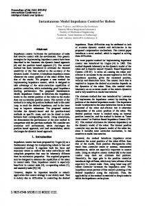
Fig. 1. Schematic of open control architecture.
Finally, with reference to the quaternion-based rotational impedance in (46), it is (61) are suitable positive gains, where and is the vector part of the quaternion that can be extracted the matrix is needed to refer the orientation from tracking error to the base frame, as for the other terms in (61). can be computed by forward integration Note that of the differential equation (46).
through the communication link at 1 ms sampling rate. Joint velocities are reconstructed through numerical differentiation of joint position readings. A six-axis force/torque sensor ATI FT 130/10 with force range of 130 N and torque range of 10 Nm is mounted at the wrist of the robot manipulator. The sensor is connected to the PC by a parallel interface board which provides readings of six components of generalized force at 1 ms. An end effector has been built as a steel stick with a wooden disk of 5.5 cm radius at the tip. The end-effector frame has its origin at the center of the disk and its approach axis normal to the disk surface and pointing outwards. The dynamic model of the robot manipulator has been identified in terms of a minimum number of parameters, where the dynamics of the outer three joints has been simply chosen as purely inertial and decoupled. Only joint viscous friction has been included, since other types of friction (e.g., Coulomb and dry friction) are difficult to model. The proposed quaternion-based impedance controller has been tested in two case studies, and its performance has been compared with that of the two impedance controllers based on operational space formulations. An analysis of the computational burden for the three controllers has been carried out for the available hardware, leading to a total time of: 0.264 ms for the impedance controller based on (2), (9), (55), (57), (58), 0.230 ms for the impedance controller based on (2), (14), (55), (57), (59), and 0.195 ms for the impedance controller based on (2), (46), (55), (57), (61). Details on the computational load in terms of floating point operations and elementary functions number are given in Table II.
V. EXPERIMENTS The laboratory setup consists of an industrial robot Comau SMART-3 S. The robot manipulator has a six-revolute-joint anthropomorphic geometry with nonnull shoulder and elbow offsets and nonspherical wrist. The joints are actuated by brushless motors via gear trains; shaft absolute resolvers provide motor position measurements. The robot is controlled by an open version of the C3G 9000 control unit (Fig. 1) which has a VME-based architecture with 2 processing boards (Robot CPU and Servo CPU) both based on a Motorola 68 020/68882, where the latter has an additional DSP and is in charge of trajectory generation, inverse kinematics and joint position servo control. Connection of the VME bus to the ISA bus of a standard PC is made possible by two Bit 3 Computer bus adapter boards, and the PC and C3G controller communicate via the shared memory available in the Robot CPU [24]; a PC Pentium/133 is used. This is in charge of computing the control algorithm and passing the references to the current servos
A. First Case Study: Interaction with Environment The first case study has been developed to analyze the interaction between the end effector and the environment. The environment is constituted by a flat plexiglas surface. The resulting translational stiffness at the contact between the end effector and the surface is of the order of 10 N/m, while the rotational stiffness for small angles is of the order of 20 Nm/rad. Two different experiments have been carried out. In the first experiment, the task consists of taking the disk in contact with the surface at an angle of unknown magnitude (Fig. 2). The end-effector desired position is required to make a straight line motion with a vertical displacement of 0.24 m along the -axis of the base frame. The trajectory along the path is generated according to a 5th-order interpolating polynomial with null initial and final velocities and accelerations, and a duration of 7 s. The end-effector desired orientation is required to remain constant during the task. The
296
IEEE TRANSACTIONS ON ROBOTICS AND AUTOMATION, VOL. 15, NO. 2, APRIL 1999
Fig. 2. End effector and the environment in the first case study.
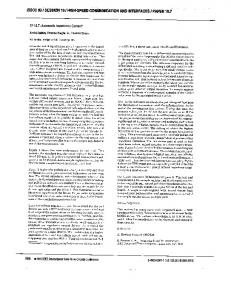
surface is placed (horizontally) in the -plane in such a way as to obstruct the desired end-effector motion, both for the translational part and for the rotational part. The parameters of the translational part of the six-DOF 9, impedance equation (2) have been set to while the parameters of the rotational part of the six-DOF impedance equation (46) have been set to Notice that the stiffness matrices have been chosen so as to ensure a compliant behavior at the end effector (limited values of contact force and moment) during the constrained motion, while the damping matrices have been chosen so as to guarantee a well-damped behavior. The gains of the inner loop control actions in (57), (61) have 2025, 4500, 65. been set to The results in Fig. 3 show the effectiveness of the proposed quaternion-based impedance controller. After the contact, the component of the position error between the end-effector along the frame and the desired frame axis significantly deviates from zero, as expected, while small errors can be seen also for the components along the - and the -axis due to contact friction. As for the orientation error, all the components of the orientation displacement between significantly the end-effector frame and the desired frame deviate from zero since the end-effector frame has to rotate with respect to the base frame after the contact in order to comply with the surface. Also, in view of the imposed task, a prevailing component of the contact force can be observed along the -axis after the contact, while the small components along the - and the -axis arise as a consequence of the above end-effector deviation. As for the contact moment referred to the desired frame, the component about the -axis is small, as expected. It can be recognized that all the above quantities reach constant steady-state values after the desired motion is stopped. The oscillations on the force and moment during the transient can be mainly ascribed to slipping of the disk on the surface after the contact. In sum, it can be asserted that a compliant behavior is successfully achieved. A similar performance has been obtained also with the impedance controllers based on the operational space formulations, i.e., by using either (9) or (14) in lieu of (46). This fact can be explained because both the absolute end-
1
d ; f ; � with impedance controller based Fig. 3. Components of ped ; �ed on (2), (46), (55), (57), (61) in the first experiment of the first case study.
effector orientation in (9) and the relative orientation in (14) keep far from representation singularities. The results are not reported here for brevity but they can be found in [5]. The second experiment is aimed at testing the performance of the quaternion-based impedance controller when the endeffector orientation is close to a representation singularity of The end-effector desired position is required to make a straight line motion with a horizontal displacement of 0.085 m along the -axis of the base frame. The trajectory along the path is generated according to a 5th-order interpolating polynomial with null initial and final velocities and accelerations, and a duration of 5 s. The end-effector desired orientation is required to remain constant during the task. The surface is now placed vertically in such a way as to obstruct the desired end-effector motion, only for the rotational part though. Therefore, no impedance control has been accomplished for the translational in (57) coincides with part, i.e., The parameters of the quaternion-based impedance equa10, tions (2), (46) are set to In order to carry out a comparison, the Euler angles-based impedance controller has also been tested. The parameters of the rotational part of the six-DOF impedance equation (9) have been set to As regards the gains of the inner loop control actions, these have been chosen equal to those in the previous experiment for both types of impedance controllers. The results in Figs. 4 and 5 show the significant differences occurring in the performance of the two schemes. For the impedance controller based on (9), large values of contact force and moment are generated since the rotational impedance this equation suffers from ill-conditioning of the matrix phenomenon is not present for the impedance controller based on (46) since representation singularities are not involved in the rotational impedance equation. On the other hand, testing of the impedance controller based on the alternative description of orientation displacement in (14) has revealed
CACCAVALE et al.: SIX-DOF IMPEDANCE CONTROL BASED ON ANGLE/AXIS REPRESENTATIONS
297
Fig. 4. Components of f ; � with impedance controller based on (2), (46), (55), (57), and (61) in the second experiment of the first case study.
Fig. 6. Components of �d and with impedance controller based on (2), (46), (55), (57), and (61) in the first experiment of the second case study.
Fig. 5. Components of f ; � with impedance controller based on (2), (9), (55), (57), and (58) in the second experiment of the first case study.
Fig. 7. Components of �d and with impedance controller based on (2), (9), (55), (57), and (58) in the first experiment of the second case study.
a performance as good as the quaternion-based impedance is kept far controller, since the orientation displacement from a representation singularity. Hence, the results are not reported here for brevity but they can be found in [5]. In sum it can be concluded that both the impedance controller based on the alternative description of orientation displacement and the quaternion-based impedance controller perform better than the classical operational space impedance controller as far as interaction with the environment is concerned.
The results in Figs. 6 and 7 show the different performance which has been in terms of the orientation misalignment defined as the norm of the vector product between the orientation error and the unit vector of the approach axis of the i.e. desired frame
B. Second Case Study: Geometric Consistency Another case study has been developed to analyze the geometric consistency when an external moment is applied at the end effector. Two different experiments have been carried out. In the first experiment, the quaternion-based impedance controller and the Euler angles-based impedance controller have been tested. The stiffness matrices of the rotational part of the impedance equations (46), (9) have been taken as diagonal matrices; has been chosen as in (40) with and and The remaining parameters of the rotational then part of the six-DOF impedance equations have been set to No impedance control has been accomplished for the translational part. The gains of the inner loop control actions have been chosen equal to those in the previous case study. The position and orientation of the desired frame is required to remain constant, and a torque is applied about the approach axis of the desired frame; the torque is taken from zero to 2.5 Nm according to a linear interpolating polynomial with 4th-order blends and a total duration of 1 s.
For the impedance controller based on (9) the instantaneous axis of rotation of the end-effector frame changes, while remarkably no misalignment occurs for the impedance controller based on (46). The impedance controller based on (14) has been also tested and its performance is as good as that of the quaternion-based controller; hence, the results are not reported for brevity. In the second experiment, the quaternion-based impedance controller and the impedance controller based on the alternative description of orientation displacement have been tested. The Euler angles-based impedance controller has been ruled out in view of the poor results of the previous experiment. This time, the principal axes of the stiffness matrices of the rotational part of the six-DOF impedance equations (46), (14) are rotated with respect to the coordinate axes of the desired has been chosen as in (40) with frame;
and then The remaining parameters of the rotational part of the six-DOF impedance have been set to As above, no
298
IEEE TRANSACTIONS ON ROBOTICS AND AUTOMATION, VOL. 15, NO. 2, APRIL 1999
Fig. 8. Components of �d and with impedance controller based on (2), (46), (55), (57), and (61) in the second experiment of the second case study.
Fig. 9. Components of �d and with impedance controller based on (2), (14), (55), (57), and (59) in the second experiment of the second case study.
impedance control has been accomplished for the translational part, and the gains of the inner loop control actions have been chosen equal to those in the previous case study. A torque has been applied about the axis whose unit vector is the torque is taken from zero to 1.5 Nm according to a linear interpolating polynomial with 4th-order blends and a total duration of 1 s. The results in Figs. 8 and 9 show the significant differences It can occurring in terms of the orientation misalignment be seen that the instantaneous axis of rotation of the endeffector frame does not appreciably rotate with the impedance controller based on (46), given the performance of the inner loop acting on the end-effector orientation error. Instead, a significant misalignment occurs with the impedance controller based on (14). In sum, it can be concluded that the quaternion-based impedance controller performs better than both impedance controllers based on the operational space formulation as far as geometric consistency is concerned.
controllers based on the operational space formulation has been shown both in theory and in practice. An inverse dynamics strategy with contact force and moment measurements has been used in the design of the various controllers which have been made robust thanks to the adoption of an inner loop acting on the end-effector position and orientation error. The controllers have been implemented on an industrial robot with open control architecture and force/torque sensor, and the results in a number of experiments have been critically compared. APPENDIX For the reader’s convenience, a few basic concepts regarding the use of a unit quaternion to describe the orientation of a rigid body and its relationship with the body angular velocity are summarized hereafter [17]. The orientation of a rigid body in space is typically described in terms of a (3 3) rotation matrix expressing the orientation of a frame attached to the body with respect to a fixed base frame. The relationship between the time derivative of the rotation matrix and the body angular velocity is given by (62) is the skew-symmetric matrix operator performing where 1) vectors. the cross product between two (3 The orientation can be described also by resorting to a fourparameter representation in terms of a unit quaternion (viz., Euler parameters) (63) (64) where and are, respectively, the rotation and the (3 1) unit vector of an equivalent angle/axis representation of orientation. Notice that the scalar part and the vector part of the quaternion are constrained by (65) and represent the same orientation. also Hence, the body frame is aligned with the base frame as long 1 and as The rotation matrix corresponding to a given quaternion is (66)
VI. CONCLUSION A class of six-DOF impedance controllers for robot manipulators interacting with the environment has been proposed in this work. By considering an angle/axis representation of the end-effector orientation displacement, an energy-based argument has lead to deriving a rotational impedance equation at the end effector, which exhibits a physically meaningful behavior and geometric consistency properties. Among the different angle/axis representations, the unit quaternion has been chosen which avoids the occurrence of representation singularities. The superior performance of the proposed angle/axisbased impedance controllers over two different impedance
Several algorithms exist to extract the quaternion from a given rotation matrix; an efficient one is reported in [25]. The above 0 for sign ambiguity is solved by choosing The relationship between the time derivative of the quaternion and the body angular velocity is established by the so-called quaternion propagation (67) (68) with (69)
CACCAVALE et al.: SIX-DOF IMPEDANCE CONTROL BASED ON ANGLE/AXIS REPRESENTATIONS
Consider now two frames, conventionally labeled 1 and and respectively denote the rotation matrices 2. Let expressing the orientation of the two frames with respect to the base frame. Then, the mutual orientation between the two frames can be described by the rotation matrix (70) As usual, a superscript denotes the frame to which a quantity (vector or matrix) is referred; the superscript is dropped whenever a quantity is referred to the base frame. The unit quaternion describing the mutual orientation can be or computed by composition either extracted directly from and that can be of the unit quaternions and respectively, i.e., extracted from (71) (72) where the double subscript denotes that a mutual orientation is of concern; the vector part of the quaternion has been referred Notice to frame 1, but it is easy to prove that is related to through a relationship formally that equal to (66). The differential kinematics relationship corresponding to (62) is (73) where (74) is the angular velocity of frame 2 relative to frame 1, which has has been introduced been referred to frame 1; the operator to denote that a vector difference has been taken. Accordingly, the differential kinematics relationship corresponding to (67), (68) becomes
299
[6] J. Lonˇcari´c, “Normal forms of stiffness and compliance matrices,” IEEE J. Robot Automat, vol. RA-3, pp. 567–572, 1987. [7] E. D. Fasse and J. F. Broenink, “A spatial impedance controller for robotic manipulation,” IEEE Trans. Robot. Automat., vol. 13, pp. 546–556, 1997. [8] E. D. Fasse, “On the spatial compliance of robotic manipulators,” ASME J. Dyn. Syst., Meas., Contr., vol. 119, pp. 839–844, 1997. [9] B. Siciliano and L. Villani, “Six-degree-of-freedom impedance robot control,” in Proc. 8th Int. Conf. Adv. Robot., Monterey, CA, 1997, pp. 387–392. [10] J. T.-Y. Wen and K. Kreutz-Delgado, “The attitude control problem,” IEEE Trans. Automat. Contr., vol. 36, pp. 1148–1162, 1991. [11] O. Egeland and J.-M. Godhavn, “Passivity-based adaptive attitude control of a rigid spacecraft,” IEEE Trans. Automat. Contr., vol. 39, pp. 842–846, 1994. [12] J. S.-C. Yuan, “Closed-loop manipulator control using quaternion feedback,” IEEE J. Robot. Automat., vol. 4, pp. 434–440, 1988. [13] R. L. Hollis, S. E. Salcudean, and A. P. Allan, “A six-degree-offreedom magnetically levitated variable compliance fine-motion wrist: Design, modeling and control,” IEEE Trans. Robot. Automat., vol. 7, pp. 320–333, 1991. [14] J. C. K. Chou, “Quaternion kinematic and dynamic differential equations,” IEEE Trans. Robot. Automat., vol. 8, pp. 53–64, Feb. 1992. [15] W.-S. Lu and Q.-H. Meng, “Impedance control with adaptation for robotic manipulators,” IEEE Trans. Robot. Automat., vol. 7, pp. 408–415, 1991. [16] F. Bruni, F. Caccavale, C. Natale, and L. Villani, “Experiments of impedance control on an industrial robot manipulator with friction,” in Proc. 5th IEEE Int. Conf. Contr. Appl., Dearborn, MI, 1996, pp. 205–210. [17] R. E. Roberson and R. Schwertassek, Dynamics of Multibody Systems. Berlin, Germany: Springer-Verlag, 1988. [18] J. Y. S. Luh, M. W. Walker, and R. P. C. Paul, “Resolved-acceleration control of mechanical manipulators,” IEEE Trans. Automat. Contr., vol. AC-25, pp. 468–474, 1980. [19] C. W. Wampler and L. J. Leifer, “Applications of damped leastsquares methods to resolved-rate and resolved-acceleration control of manipulators,” ASME J. Dyn. Syst., Meas., Contr., vol. 110, pp. 31–38, 1988. [20] F. Caccavale, B. Siciliano, and L. Villani, “Quaternion-based impedance with nondiagonal stiffness for robot manipulators,” in Proc. 1998 Amer. Contr. Conf., Philadelphia, PA, 1998, pp. 468–472. [21] J.-J. E. Slotine and W. Li, Applied Nonlinear Control. Englewood Cliffs, NJ: Prentice-Hall, 1991. [22] F. Caccavale, C. Natale, B. Siciliano, and L. Villani, “Resolvedacceleration control of robot manipulators: A critical review with experiments,” Robotica, vol. 16, pp. 565–573, 1998. [23] F. Caccavale and P. Chiacchio, “Identification of dynamic parameters and feedforward control for a conventional industrial manipulator,” Contr. Eng. Practice, vol. 2, pp. 1039–1050, 1994. [24] F. Dogliani, G. Magnani, and L. Sciavicco, “An open architecture industrial controller,” IEEE Robot. Automat. Soc. Newsl., vol. 7, no. 3, pp. 19–21, 1993. [25] S. W. Shepperd, “Quaternion from rotation matrix,” AIAA J. Guid. Contr., vol. 1, pp. 223–224, 1978.
(75) (76) with
defined as in (69). REFERENCES
[1] N. Hogan, “Impedance control: An approach to manipulation, Parts I–III,” ASME J. Dyn. Syst., Meas., Contr., vol. 107, pp. 1–24, 1985. [2] J. K. Salisbury, “Active stiffness control of a manipulator in Cartesian coordinates,” in Proc. 19th IEEE Conf. Decision Contr., Albuquerque, NM, 1980, pp. 95–100. [3] O. Khatib, “A unified approach for motion and force control of robot manipulators: The operational space formulation,” IEEE J. Robot. Automat., vol. RA-3, pp. 43–53, 1987. [4] L. Sciavicco and B. Siciliano, Modeling and Control of Robot Manipulators. New York: McGraw-Hill, 1996. [5] F. Caccavale, C. Natale, B. Siciliano, and L. Villani, “Experiments of spatial impedance control,” in Proc. 5th Int. Symp. Experimental Robot., Barcelona, Spain, and in Experimental Robotics V, A. Casals and A. T. de Almeida, Eds. London, U.K.: Springer-Verlag, 1998, pp. 93–104.
Fabrizio Caccavale (M’98) was born in Naples, Italy, on November 14, 1965. He received the Laurea degree and the Research Doctorate degree in electronic engineering from the University of Naples, Naples, Italy, in 1993 and 1997, respectively. Since 1997, he has been with the University of Naples and is now a Post-Doctorate Fellow of Robotics, Department of Computer and Systems Engineering. From April to October 1996, he was a Visiting Scholar with the Department of Electrical and Computer Engineering, Rice University, Houston, TX. His research interests include manipulator inverse kinematics techniques, cooperative robot manipulation, and nonlinear control of mechanical systems. He has published more than 30 journal and conference papers.
300
IEEE TRANSACTIONS ON ROBOTICS AND AUTOMATION, VOL. 15, NO. 2, APRIL 1999
Ciro Natale (S’98) was born in Caserta, Italy, on December 12, 1969. In 1995, he received the Laurea degree in electronic engineering from the University of Naples, Naples, Italy, where he is currently pursuing the Research Doctorate degree in electronic engineering. From November 1998 to May 1999, he was a Visiting Scholar with the Institute of Robotics and System Dynamics, DLR (German Aeorospace Center), Oberpfaffenhofen, Germany. His research interests include force/motion control of manipulators and visual servoing. Mr. Natale received the 1996 UCIMU award for the section “Robots: Design and Applications,” from his Laurea thesis.
Bruno Siciliano (M’91–SM’94) was born in Naples, Italy, on October 27, 1959. He received the Laurea degree and the Research Doctorate degree in electronic engineering from the University of Naples, in 1982 and 1987, respectively. Since 1987, he has been working with the Faculty of Engineering, University of Naples, where he is an Associate Professor of Robotics in the Department of Computer and Systems Engineering. From September 1985 to June 1986, he was a Visiting Scholar with the School of Mechanical Engineering, Georgia Institute of Technology, Atlanta. His research interests include manipulator inverse kinematics techniques, redundant manipulator control, modeling and control of flexible arms, force/motion control of manipulators, and cooperative robot manipulation. He has published more than 150 journal and conference papers, he is coauthor of the books Modeling and Control of Robot Manipulators with Solutions Manual (New York: McGraw-Hill, 1996) and Theory of Robot Control (London, U.K.: Springer-Verlag, 1996), he is co-editor of the book Control Problems in Robotics and Automation (London, U.K.: Springer-Verlag, 1998). He has delivered more than 70 invited seminars and presentations at international institutions. Dr. Siciliano is a member of ASME, served as Associate Editor of the IEEE TRANSACTIONS ON ROBOTICS AND AUTOMATION from 1991 to 1994, and Associate Technical Editor of the ASME Journal of Dynamic Systems, Measurement, and Control from 1994 to 1999. He is also on the editorial advisory boards of Robotica and the JSME International Journal. Since 1996, he has been an Administrative Committee Member of the IEEE Robotics and Automation Society (re-elected in 1999), Chair of the Technical Committee on Manufacturing and Automation Robotic Control of the IEEE Control Systems Society. In February 1999, he was appointed Vice President for Publications of the IEEE Robotics and Automation Society. He has been on the program committees of several international robotics conferences. He has been Program Chair of the IEEE International Workshop on Control Problems in Robotics and Automation: Future Directions (1997), Program Vice-Chair of the 1998 and 1999 IEEE International Conference on Robotics and Automation, and he is General Co-Chair of the 1999 IEEE/ASME International Conference on Advanced Intelligent Mechatronics.
Luigi Villani (S’94–M’96) was born in Avellino, Italy, on December 5, 1966. He received the Laurea degree and the Research Doctorate degree in electronic engineering from the University of Naples, Naples, Italy, in 1992 and 1996, respectively. Since 1996, he has been with the University Naples and is a Post-Doctorate Fellow of Robotics, Department of Computer and Systems Engineering. From June to October 1995, he was a Visiting Scholar with the the Laboratoire d’Automatique de Grenoble, Institute National Polytechnique de Grenoble, France. His research interests include force/motion control of manipulators, adaptive, and nonlinear control of mechanical systems. He has published more than 40 journal and conference papers, and is coauthor of the booklet Solutions Manual to Modeling and Control of Robot Manipulators (New York: McGraw-Hill, 1996).