Sketch-based Route Planning with Mobile Devices in immersive Virtual Environments Sebastian Kn¨odel∗
Martin Hachet†
Pascal Guitton‡
INRIA - University of Bordeaux
Abstract We present a novel sketch-based route planning technique, that supports the collaborative work of a group of people navigating through a virtual environments using mobile devices. With our new approach, route planning tasks, like creating camera animation paths, can be generated very efficient, while working on large screens with complex data. Our interaction technique lets the user explore the distributed environment in a two stage process. During the first stage, the user draws the preferred navigation path directly onto a touch sensitive mobile device, that presents the data as a “World in Miniature”. Afterward, during a second stage, the user can define areas of interest by performing additional sketches, like drawing points, lines or circles, to easily define the camera orientation during the animation. Based on the sketched input, the system creates automatically the optimal animation path and camera orientation, so that disturbing occlusions are avoided and all areas of interest are in view. CR Categories: I.3.7 [Computer Graphics]: Three Dimensional Graphics and Realism—Artificial, augmented and virtual realities; Keywords: Virtual Reality, Interaction Techniques, PDA interaction, Animation
1
Introduction
With large screens, several co-located participants can visualize the same image at the same time. Therefore, these equipments are very powerful for collective visualization tasks such as project review in companies or virtual visits for cultural heritage applications in museums. For such applications, an operator can pilot the interactive walkthrough by means of navigation devices. However, interactive 3D navigation in front of large screens remains a difficult task. Fluid movements are difficult to maintain by the operator, particularly with complex environments where true real-time is not always insured. Hence, the camera movements controlled by a third person often causes nausea to the audience. To avoid motion sickness, predefined smooth animation paths are generally used, which breaks the interactivity between the audience and the virtual environments. To let the users decide where they want to travel to in the VE while insuring smooth camera movements, we propose a novel approach based on a exocentric metaphor, whereas a mobile device (PDA, Tablet PC) presents a “World in Miniature” the user can interact with directly. The sketched input results in a smooth camera animation path through the virtual environment, which is presented on a large screen. The Navigation through complex models, like large landscapes or cities, is still a hard challenge. This is especially difficult, if high ∗ e-mail:
[email protected] † e-mail:
[email protected]
‡ e-mail:
[email protected]
resolution tiled screens or stereo projection systems are used to present the data to the user. In particular, if the user is rather interested in paying attention to certain information of the surrounding, than to solve the steering task. To do so, the user may want to plan the travel in advance to be able to pay attention to objects, he is really interested in. In this special case, classic steering navigation is not suitable, because it forces the user to focus on the navigation task. Regarding this, the planning of the desired route in advance has several advantages. The system can support the user by optimizing the given input and solving tasks, he is not willing to do by himself, like steering through the environment and avoiding occlusions. Our route planning system allows the user to specify a path through the environment and lets him define interesting areas by choice. After that the system computes an optimized camera movement and orientation along the defined. Meaning that the user plans and the system carries out the given instructions. This gives the user the possibility to focus on other tasks, such as information gathering. There exist a variety of interaction devices to navigate through a virtual environment, that is presented on a large screen, for example the Wand or Stylus , the GyroMouse, FlyStick or the CAT[Hachet and Guitton 2004]. Some of them provide six or more degrees of freedom, hence they allow the user to control at the same time translation and orientation of the camera. These are manageable tools, that are useful for steering tasks but not necessarily during a route planning tasks. This makes such a particular task difficult, especially for novice users that or not familiar with 3D input devices. Ware[Ware and Osborne 1990] proposed the ”flying vehicle control” interaction metaphor, where system records the motion path followed during an exploration session using a six degree of freedom interaction device. This could be recorded and played hack to create a movie. But this metaphor is not useful to plan a route in advance, because the user has to define the route in 3D space while traveling through it. During route planning tasks in complex virtual environments the definition of a certain path, the camera should follow, is difficult. The user usually does not have a overall knowledge of the whole virtual environment. Controlling the camera orientation in a way, that all objects of interest will be visible and in view, while traveling through the environment can be very difficult. Therefore we propose the use of mobile technology for route planning in virtual environments. Mobile devices have several advantages compared to the previously introduced 3D interaction tools. They are easy to use, portable and their computational capacities are adequate to visualize and interact with rather complex scenes. They are also small, lightweight, not stationary and the pen-based interaction is a well know interaction metaphor to novice users. Especially, the touch sensitive screen, which is familiar to wide public, is adapted to be used as an interaction interface for a three dimensional environment.
2
Related Work
Interaction through mobile devices in immersive and semiimmersive VEs has been investigated in previous works. The project ”‘Chameleon”’ [Fitzmaurice et al. 1993] and in their other work [Fitzmaurice and Buxton 1994] explored how virtual reality theories could be applied toward mobile devices. Another approach by [Watsen et al. 1999] investigate the contention between 2D and 3D interaction metaphors. The JAIVE project [Hill and Cruz-Neira 2000] extends previous effort integrating wireless networking, utilizing JAVA and accommodating custom design interfaces. [Simon 2005] developed an interaction paradigm allowing users to share a virtual environment in a conventional CAVA like display system. The interaction based on ray casting and direct object manipulation using tracked PDA’s. Our approach bases on the World in miniature interaction by [Stoakley et al. 1995]. The mobile device presents the virtual environment from exocentric perspective so that the user is able to see as much of the environment he probably want to interact with. Of course that approach is limited to a certain kind of virtual environments that has a planar characteristic like terrains, city models or parts of buildings. In their work ”Sketching 3d animations”[Balaguer and Gobbetti 1995] presented novel general purpose tool that allows the user to create animations using straight-ahead actions in three dimensional space. A very basic approach to sketch animation paths directly into the virtual environment was presented by [Igarashi et al. 1998]. And [Bowman et al. 1999] described in his work a route-planning technique, where subjects use the stylus to place markers on the 3-D map of the corridor to define a path. Hereby, the user defines points in classic ”World in Miniature”, which is presented inside the virtul environment. After that the user travels from point to point through the model. The resulting animation is very simple, because no smooth B-Spline path was calculated.
era follows. Consequently the user controls indirectly the camera motion presented on the large screen. We use the keyframing in our system to obtain a smooth animation. It is the most prevalent motion control technique and easy to implement. By specifying a sequence of key values, which are in our case control points of the sketched animation path, the system associates time values and calculates automatically continuous in-between values using an interpolation method. We use uniform cubic B-Splines to obtain a smooth animation by interpolating the acquired control points. The equation 1 presents the general definition of a Basis-Spline Curve (B-Spline Curve) C(u) of degree n with control points Pi , the basis functions Nin (u), the knot vector ti and u ∈ [t0 , tn+m ]. C(u) =
m−1 X
Pin (u)bi
(1)
i=0
We use in our system uniform cubic B-Spline curves, because the blending function can easily be pre-calculated, and it is equal for each segment in this case. The matrix-form of a uniform cubic BSpline is −1 3 1 3 2 C(u) = [u +u +u+1] 6 −3 1
3 −6 0 4
−3 3 3 1
1 pi−1 0 pi 0 pi+1 0 pi+2
f or ∈ [0, 1] (2)
[Thorne et al. 2004] extended that concept to sketch and animate stick figures in a virtual environment and showed a working example with a tablet PC and a touch sensitive screen.
3
Sketch-based control of the Camera Motion and Orientation
Navigating through large landscapes and city models is of big interest for city planers or emergency control centers. Thanks to the availability of new powerful technology like HD stereo projection displays that are driven by a distributed cluster of servers, the presentation of complex data with advanced visualization algorithms is getting common. Our novel approach lets the user interact with such a complex virtual environment by sketching on a mobile device, like a PDA or Tablet PC, that act as a world in miniature presenting the scene from an exocentric point of view. This allows the user to interact directly by sketching 2D strokes using a pen. This is an interaction metaphor, that is known to wide public and therefore a convenient way to solve tasks like route planning. Hereby the mobile devices works like a virtual map, where the user indicates with a pen which route he wants to travel.
3.1
Sketching the Animation Path
The idea is that the user can draw easily a path directly into the environment the camera will follow. With the given input the system calculates automatic a 3D animation B-Spline path, that the cam-
(a)
(b)
(e)
(c)
(f)
(d)
(g)
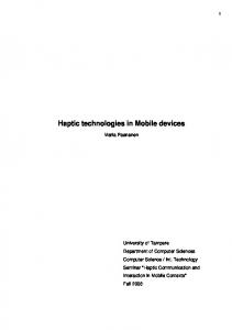
Figure 1: (a) sketched input stroke (b) sampled control points and control hull (c) control hull and generated B-Spline (d) resulting BSpline Animation Path (e),(f) and (g) show three example views of the resulting animation We decided to use B-Spline curves, because they have several useful properties. For instance, the affine invariance property, which
states, that we can apply any affine transformation (translation, rotation or scale) to control points, which is quite easy, and once the transformed control points are obtained the transformed B-spline curve is the one defined by these new points. Therefore, we do not have to transform the curve. As well the local modification property, which means that changing the position of a control point only affects a local curve segment, but not the whole curve. So we can change the position of a control point without globally changing the shape of the whole curve. This property allows us, for instance, to easily optimize the animation curve in a post-processing step.
(a)
(b)
To compute the uniform B-Spline animation path, we have to acquire control points in three dimensional space from the sketched two dimensional stroke. Therefore we sample a certain amount of candidate pixels from the drawn stroke. After that we compute 3D points on the surface for every sampled 2D point, using information provided by the depth buffer. These 3D points will act as control points from which we calculate a smooth b-spline. This resulting B-Spline is the animation path the camera moves along through the environment. It is necessary to add an offset to every computed control point otherwise the camera would move directly onto the surface which would result in inconvenient camera perspectives. This offset is calculated by analyzing the extent of the virtual environment, whereas we assume that the users wants to move close to the ground but far enough to avoid humble position like a worm’s-eye view. The animation path sketching procedure is illustrated in the figures 1 (a) to (d). Figure 1(a) shows the sketched path (red line ), after that the system samples the sketch and calculates the control points (blue points) with the control polynom (orange line), which can be observed in figure 1(b). Finally our system calculates the B-Spline path (green line) shown in figure 1(c) and (d). The figure 1(e), (f) and (g) present three resulting camera perspectives of the final animation.
3.2
Sketching the Camera Orientation
By default the camera is oriented along the animation path, which is not always preferable. Therefore the user can observe the environment by rotating the camera performing simple pen strokes moving along the path, similar to a trackball rotation. Furthermore, our system allows the user to predefine the orientation during the animation by pointing at elements, drawing lines at regions of interest or circle whole areas of interest. This given input is used to calculate camera orientations that correspond with the previously defined animation path, so that all information the user is interested in will be visible during the animation. In any case the system allows the user to interfere and modify the camera orientation at all times during the animation. 3.2.1
Default Camera orientation
The most simple approach is to orient the camera along the precomputed animation path. But this can be very annoying if there are areas of certain interest, the user wants to observe, but he has to reorient the camera by himself to see these areas properly. For instance, architects or city planners usually have a certain idea of what they want to look at or what they probably want to present on a large screen, while they are moving through a virtual environment. Therefore our idea is to introduce a second input stage, whereas the user can define the camera orientation by easy sketchbased interactions.
(c)
Figure 2: (a) orientation defined by sketching points (blue)(b) by drawing a path of interest (red) (c) sketched area of interest (red) and resulting rectangle area of interest (blue)
3.2.2
Defining Points of Interest
This interactive possibility allows the user to define several points of interest on the surface the camera should be oriented to during the animation. These points act as control points of a B-Spline curve, similar to the animation path, where the system calculates a smooth B-Spline, that controls the orientation of the camera. The result can be observed in figure 2(a), where the camera will be oriented to the orientation path during the animation(red) computed from the previously sketched control points (blue). 3.2.3
Drawing a Path of Interest
Another interactive possibility to sketch the camera orientation is to draw a path of interest directly onto the surface, which the camera is going to orient to. Then certain points of the sketched path are used to generate a smooth three dimensional B-Spline curve. The algorithm which is used to calculate that path is similar with the one that is used to compute the animation path for the camera. The orientation path drawing is shown in figure 2(b), where the red line represents the sketched path of interest and the green line the animation path. 3.2.4
Sketching Areas of Interest (AoI)
Usually the user is not interested in certain points but in certain areas he wants to observe. Using our system the user has the possibility to circle areas he is interested in and the system computes the camera orientation. It also optimizes the animation path so that a maximum of every circled area of interest is in view. For every detected circled area the system computes the 2D extents, that define the bounding box of the AoI. With the minimum extents of the 2D bounding box we can easily determine the center of that Box. After that we calculate the depth value for every pixel that is
located inside the AoI. Then the system computes the average depth value of all these pixels of interest. In the next step the position of the AoIs bounding box in world space is calculated, but this point would not correctly represent the AoI, because it is located on top of the surface. Using this point, the camera would be oriented to the top of the object, which is usually inappropriate. Instead we use the computed average depth value of all pixels, because it lies inside the 3D bounding box of the sketched AoI, so that the camera view will cover not only the top of the object, but the center of it.
method can be observed in figure 3(b). Every control point will be only optimized one time. The figures 4 (a) to (c) illustrate the previously described optimization. In picture 4(a) the resulting camera animation path is visible. In figure 4(b) the areas of interest were added and it can be observed, that the animation path is probably to proximate to them. In the next figure 4(c) the resulting animation path (green) is shown, after the optimization process. Figure 5(d), (e) and (f) show the final camera perspectives of the new animation path.
This procedure is done for every AoI, which results in a list of 3D points, that were used as control points to create a B-Spline path that describes the camera orientation during the animation. This may be not sufficient, because if the camera animation path pass the AoI very close, the resulting view will be inconvenient. Therefore we introduced an additional optimization step, that optimizes the camera animation path in a way, that the sketched AoI will be in view. This procedure is described in section3.3. Another interaction problem, which we observed was that the user prefers to sketch the AoI without any order. He is expecting that the system will define automatically the order of the sketched AoI, that will be visible during the animation. So it is necessary to order the AoIs, because we compute a orientation B-Spline Path, that should correspond with the animation path. Meaning that the closest AoI relative to the current position should be visible.
Figure 3: scheme that shows the optimization process
Thus the system determines the closest control point of the animation B-Spline path for every Area of interest. Subsequently the list of AoI control points is getting sorted relative to the corresponding control polygon animation path. Which means, that the control points of the resulting camera orientation path, that defines where the camera is looking at, will correspond with the camera animation path. Meaning that, if a position of the animation B-Spline is evaluated, the point on the orientation path is as proximate as possible. If multiple AoIs are close to the same control point of the animation path, the closest one will be sorted in front of the list for the certain control point. This should guarantee, that the user will see the area of interest he is interested in when he is close to it.
3.3
(a)
Animation Path Optimization
Since the user interacts with a relatively small sized touch pad of a Tablet PC or PDA, is it possible that the sketched animation path passes close to an object of interest. As a result the object would not be completely visible to the user as shown in figure 5 (a), (b) and (c). Our system is able to correct this error by optimizing the animation path based on the predefined areas of interest. First we calculate the optimal distance to the AoI, that defines the position wherefrom the whole object would be in-view. Therefore we have to calculate the Bounding Box of every AoI and create a bounding sphere using the maximal extent as the radius. With the known field of view f ov of the camera the minimal distance d can be calculated easily using equation 3. Meaning that, if the camera is within distance d to the AoI of interest, the bounding sphere will be fully visible as well as the object inside. Figure 3(a) illustrates the described method. d=
r tan( f 2ov )
(3)
If the system computed the optimal distance every AoI, we check every control point of the animation path, whether it is within distance d to the AoI. If it is to close, we transform that control point by calculating a vector from the AoIs center to the control point and translating it on that vector until it is sufficiently far away. That
(b)
(c)
Figure 4: (a) unoptimized path (b) unoptimized path with sketch AoIs (c) optimized path relative to AoIs
4
Route planning in a distributed immersive Environment
Our system was set up as the classic client server approach, where the tablet PC act as a client, that process the sketched input and sends the computed data, like animation and orientation path, to a remote server. This server visualizes the data and presents the animation on a large Tiled Screen with two HD projectors; by choice also using a stereo projection system. The client sends the data using standard TCP/IP protocol using a wireless connection. The advantage of that approach is that the client does not need to render the whole high resolution data, but only a low resolution level of detail. Hence the rendering does not obstruct the interaction on the tablet PC, since it is done in real time. However the server has the resources to display the full resolution data with shader and high quality lighting. Consequently our system is fully interactive during the animation, thus the user can modify the current camera orientation, while sketching on the tablet PC, if the presented camera view does not meet the desired perspective.
5
Conclusion and future work
One central idea was to separate the interacting environment, by using the ”World in Miniature” metaphor with the tablet PC, from the visualization environment. In that way our system is able to provide fluid interaction and high quality visualization. Because the server provides more cpu, memory and gpu capacity, than the limited computational power of the tablet or even the PDA. So the observers can comfortably concentrate on gathering certain information inside the presented scenery, without the need of solving complex navigation tasks. (a)
(b)
(c)
(d)
(e)
(f)
The advantage of our system is the fact that the user with the tablet PC has an overview of the whole scene and can interact with it in an easy way by sketching 2D strokes. For the kind of collaborative interaction we want to support, our technique seems to be more comfortable than existing interaction techniques, that let the users interact directly within the presented environment by controlling six degrees of freedom. Indeed, we provide the possibility to modify the current camera orientation, but this is in some situations not sufficiently, because the user may want to redefine the animation during the animation. In contrast, devices with more degrees of freedom offer that possibility, so we have to develop an interface, that overcomes that problem but still bases on simple sketches. In certain cases the movement of the camera is inconvenient due to fast camera turns.
Figure 5: figures (a), (b) and (c) present unoptimized views, because the animation path pass immediate proximity to the AoIs, figures (d), (e) and (f) present the resulting view after optimizing the animation relative to the size of the AoIs
Finally distant interaction with large data presented in an immersive environment is still difficult especially for a group of people. Our sketched based route planning system is meant to be used as a remote interaction technique for groups of people to support the interaction in an immersive and distributed virtual environments. For instance wandering in a virtual museum, discovering large city or landscape models, as shown in figure 6. Hereby the mobile device presents the virtual environment as a ”World in Miniature”, wherein the user can sketch the animation path as well as the regions he wants to watch during the presentation. After that the resulting animation is shown on a large projection screen. In that way our system can support the collaborative work of groups of people in an immersive environment with large virtual models.
References BALAGUER , J., AND G OBBETTI , E. 1995. Sketching 3d animations. Computer Graphics Forum 14, 3, 241–258. B OWMAN , D. A., DAVIS , E. T., H ODGES , L. F., AND BADRE , A. N. 1999. Maintaining spatial orientation during travel in an immersive virtual environment. Presence: Teleoper. Virtual Environ. 8, 6, 618–631. Figure 6: Exploring the virtual in collaboration with a group of people.
F ITZMAURICE , G., AND B UXTON , W. 1994. The chameleon: spatially aware palmtop computers. In CHI ’94: Conference companion on Human factors in computing systems, ACM Press, New York, NY, USA, 451–452. F ITZMAURICE , G. W., Z HAI , S., AND C HIGNELL , M. H. 1993. Virtual reality for palmtop computers. ACM Trans. Inf. Syst. 11, 3, 197–218.
(a)
(b)
(c)
Figure 7: (a) Navigating through a virtual museum, around a Mount Elbert model(b) or city scene(c)
H ACHET, M., AND G UITTON , P. 2004. The cat - when mice are not enough. In Proceedings of IEEE VR 2004 Workshop: Beyond Glove and Wand Based Interaction, 66–69. H ILL , L. C., AND C RUZ -N EIRA , C. 2000. Palmtop interaction methods for immersive projection technologysystems. In PT 2000.
I GARASHI , T., K ADOBAYASHI , R., M ASE , K., AND TANAKA , H. 1998. Path drawing for 3d walkthrough. In ACM Symposium on User Interface Software and Technology, 173–174. S IMON , A. 2005. First-person experience and usability of colocated interaction in a projection-based virtual environment. In VRST ’05: Proceedings of the ACM symposium on Virtual reality software and technology, ACM Press, New York, NY, USA, 23– 30. S TOAKLEY, R., C ONWAY, M. J., AND PAUSCH , R. 1995. Virtual reality on a wim: Interactive worlds in miniature. In Proceedings CHI’95. T HORNE , M., B URKE , D., AND VAN DE PANNE , M. 2004. Motion doodles: an interface for sketching character motion. In SIGGRAPH ’04: ACM SIGGRAPH 2004 Papers, ACM Press, New York, NY, USA, 424–431. WARE , C., AND O SBORNE , S. 1990. Exploration and virtual camera control in virtual three dimensional environments. SIGGRAPH Comput. Graph. 24, 2, 175–183. WATSEN , K., DARKEN , R., AND C APPS , M., 1999. A handheld computer as an interaction device to a virtual environment.