Feb 3, 2004 - [6] K. Takayama, Talk on a Superbunch VLHC at the. Hadron Colliders Working Group, Snowmass 2001. [7] F. Ruggiero, F. Zimmermann, ...
EUROPEAN ORGANIZATION FOR NUCLEAR RESEARCH CERN-AB DEPARTMENT CERN-AB-2004-011 (ABP)
Contributions to the 30th Advanced ICFA Beam Dynamics Workshop on High Luminosity e+e- Collisions "FACTORIES’03" SLAC, Stanford, 13-16 October 2003
F. Zimmermann , J.-P.Koutchouk, J. Wenninger
30th Advanced ICFA Beam Dynamics Workshop on High Luminosity e+e- Collisions "Factories’03 SLAC, Stanford, 13-16 October 2003
Geneva, Switzerland AB/DEP/Reps
3 February, 2004
CONTENTS
1.
Summary of the Working Group on IR Design, Beam-Beam Interaction and Optics F. Zimmermann, CERN
2.
Brief Review of Super-Bunches for Hadron Colliders F. Zimmermann, CERN
3.
Raimondi-Seryi Final Focus for e+e- Factories? F. Zimmermann, CERN
4.
Weak-Strong Model for the Combined Effect of Beam-Beam Interaction and Electron Cloud F. Zimmermann, CERN
5.
Compensating Parasitic Collisions Using Electromagnetic Lenses J.-P. Koutchouk, J. Wenninger, F. Zimmermann , CERN
e+e- Factories’03, Stanford, October 13-16, 2003
Summary of the Working Group on IR Design, Beam-Beam Interaction and Optics F. Zimmermann CERN, 1211 Geneva 23, Switzerland The Factories’03 ICFA Beam Dynamics Workshop was held at SLAC from October 13 to 16, 2003. The workshop was organized in three working groups. In this report, I summarize the highlights of the working group on interaction-region (IR) design, beam-beam interaction and optics, emphasizing the suggestions for future studies and pointing out the open questions.
1. INTRODUCTION The working group convened for three consecutive days. The first day was devoted to the IR, with several presentations on design issues and limitations at PEP-II and KEKB, as well as at their Super-B upgrades, and at eRHIC. The second day addressed beam-beam issues, with talks covering simulations for PEP-II, KEKB, VEPP-2N, measurements at PEP-II, analytical estimates, the interplay of beam-beam interaction and electron cloud, the compensation of parasitic collisions by electro-magnetic lenses, experience with negative alpha lattices and luminosity optimization of proton colliders using superbunches. The third day first looked at a few specific optics questions, mainly for PEP-II and eRHIC. This was followed - in a joint session with the rf working group - by presentations on the exciting upgrade plan of PEP-II, on a novel rf focusing scheme for DAFNE, and on a further analytical approach to the combined effect of beam-beam interaction and an electron cloud or space charge. In total 22 presentations were given in this working group, namely 6 on the IR design, 10 on the beam-beam interaction, and another 6 in the final session on optics and upgrade recipes.
2. IR DESIGN The IR session started out with design issues for the eRHIC Interaction Region, presented by C. Montag. In eRHIC, 10 GeV electrons will collide with 100 GeV/nucleon Au ions. Both beams are polarized. A small ion-beam emittance is maintained by electron cooling. There is no crossing angle. The presently favored optics solution considers flat beams with a 4:1 ratio in the IP beta functions of the proton beam (1 m and 0.26 m). For the electron beam, the IP beta functions are 0.19 m in both planes, while the emittances are different. The nominal tune-shift parameters are ξx,y=0.031, 0.061 for the electrons and ξx,y=0.0074, 0.0037 for the protons. The proton rms bunch length is 15 cm. The final quadrupole magnets are combined function magnets with dipole windings that facilitate the separation of the two beams. The synchrotron radiation (SR) in the IR region is quite moderate, if compared with the B factory-upgrade plans. The SR fan from the combined-function magnets carries a power of 1 kW with a critical energy of less than 11 keV. The power hitting the septum was minimized in the optics design. Beam-beam simulations were performed for a PSN THS01
slightly reduced proton current, corresponding to an electron tune shift ξx,y=0.05. The tentative time schedule foresees commissioning around 2013. In the discussion, A. Zholents and M. Furman pointed out that two-ring colliders with unequal circumferences may suffer from an enhanced number of resonances, and that this problem had been studied both by K. Hirata and E. Keil [2] and also by A. Aleksandrov and D. Pestrikov [3]. M. Sullivan next discussed possible upgrades to the PEP-II Interaction Region [4]. The motivation of the PEPII IR upgrade is to reduce βy*, from 12.5 mm via 8.5 mm down to 6.5 mm at a higher current in 2006/7. An optional crossing angle of +/-3.25 mrad is contemplated. The crossing angle would reduce the amount of synchrotron radiation generated in the IR, and it would also lower the beam-beam effect from the parasitic collisions, possibly allowing one to fill every rf bucket. Depending on whether or not a crossing angle is included, two alternative upgrade options are under investigation. The first option replaces the last 20 cm of the final permanent dipole magnet B1 by a quadrupole field, in which case the loss in bending angle is compensated by a crossing angle. This change in the magnet layout moves the vertical focusing closer to the collision point. At the same time it minimizes the hardware changes required. The second option increases the strength of the quadrupole magnet QD1, without changing its position, which can be accomplished by using a higher-strength permanent magnet. In this case, the headon collisions are kept. For both options, the adequacy of the existing synchrotron-radiation (SR) shielding is ensured by preserving the present beam orbits within a few mm. Only a few chambers need more careful attention, e.g., at the multi-tipped LER mask the SR power increases from the present level of 30 W/mm to 65 W/mm. About 165 kW of SR power will be generated inside the permanent IR magnets, with a critical energy of about 40 keV. A detailed parameter study is necessary to decide between the two options. In particular, the trade off in luminosity degradation due to the crossing angle on the one hand and due to the parasitic beam-beam encounters on the other hand needs to be investigated more carefully. Higher-order mode (HOM) heating in the IR is another item requiring further consideration. A. Seryi reviewed recent impressive progress in PEP-II IR alignment [5]. His study was motivated by an apparent strong correlation between the settings of the IR orbit correctors controlled by an automated feedback and the beam current, which hinted at IR magnet motion. A
e+e- Factories’03, Stanford, October 13-16, 2003 possible mechanism is that synchrotron radiation increases the temperature of the magnets or their supports. The ensuing thermal expansion could then change the magnetic centre of the IR quadrupoles with respect to the beam. To study this phenomenon, a comprehensive suite of alignment diagnostics has been installed in the PEP-II IR. This diagnostics comprises tilt meters, hydrostatic sensors from BINP, a stretched wire, and a laser tracker system, mounted on both sides of the collision point. Position data taken for several magnets allow a reconstruction of the observed orbit motion. A. Seryi showed a movie illustrating the motion of magnets left and right of the collision point. The magnet motion sampled over a few days exhibits typical amplitudes of 100 microns and a raft pitch of the order of 30 µrad. As expected, the motion of the magnets is correlated with the beam current. The characteristic “warm-up time constant” is about 10-15 minutes. The motion on the left side of the interaction point (IP) is much larger than on the right side. It is caused by the LER SR shine. Presently a more refined model of the magnet motion is under development. Such model might eventually be used for a feed-forward orbit correction. The list of possible remedies also includes mechanical design modifications and, especially, the isolation of the magnets from the vacuum chamber. In addition, now that the source of the motion is understood, it is possible to optimize the orbit feedback and orbit correction so as to efficiently react to this particular source of perturbation. M. Sullivan next reviewed design principles for Super-B factory interaction regions [6]. To alleviate the SR load, the incoming beam is commonly placed on axis, so that SR is generated mainly downstream of the IP. The final quadrupole Q1 is shared, so that one beam is always bent in this magnet. The second quadrupole Q2 must be a septum magnet, and a typical design criterion is to provide a beam separation by at least 100 mm at this magnet. The beam-pipe radius at the septum is minimized. The strong solenoid field of the detector requires that the final quadrupole be either a permanent magnet or superconducting. To ensure adequate shielding from background, collimators, masks and shielding walls are installed. A generic Super-B factory may have a vertical IP beta function βy*=1.5 mm and a crossing angle of +/-12 mrad. Operating with every rf bucket filled, it can provide a luminosity of 1036 cm-2 s-1. The final quadrupole Q1 may need to be offset so as to minimize the torque experienced in the solenoid field of the detector, as was elaborated in discussions with reference to B. Parker’s plenary presentation [7]. The high current implies non-negligible background as well as substantial amounts of HOM and SR power. Even resistive losses in the chamber components become important. An asymmetric elliptical IR chamber was suggested as one option for improving the vertex resolution, that at the same time maintains a sufficient horizontal aperture and does not intercept the SR fan in the immediate vicinity of the IP. Longitudinally tilted quadrupoles were also contemplated by the audience, PSN THS01
2
for balancing constraints from optics, SR, magnet torque and beam separation. The SR fan in the PEP-II design studies is based on a beam envelope of 10σ, which is augmented by a rough model of beam tails, where the tail population is estimated from the assumed beam lifetime. The IR design for Super-KEKB was described in detail by Y. Funakoshi. The beam current in the two KEKB rings is limited by the present rf system to maximum values of 9.4 A and 4.1 A, respectively. The horizontal beta function will be squeezed from 33 to 20 cm, and the vertical beta function will be 3 mm (about 6 mm at the moment). The crossing angle will moderately be increased from 11 to 15 mrad, maintaining the present electron orbit in the IR region and only modifying the positron orbit. The horizontal emittance must be increased from 18 nm to 24 nm, which optimizes the luminosity according to strongstrong beam-beam simulations. The rms bunch length is reduced to 3 mm, i.e., the same value as the decreased βy*. The ring acceptance might prove marginal for the positron emittance from the linac, which motivates studies of a dedicated positron damping ring. The acceptance of the ring depends on the beta function at the injection point. For low values of βy*, the energy acceptance becomes a problem. The KEKB final quadrupole QC1 is superconducting and of compact size. For the envisioned beam currents of 9 and 4 A, the synchrotron radiation power in the quadrupole bores is of the order 100-200 kW with a critical photon energy of 55 keV. The aperture requirements are estimated considering a beam size of 3σ and a contribution from the closed orbit. The latter takes into account orbit drifts, artificial bumps, and “iBump tuning”. The closed-orbit component was estimated from the operational experience at KEKB, where the IP offset varies by +/-0.73 mm, which translates into +/-0.37 mm at Super-KEKB. The IP angle in KEKB fluctuates by +/-0.5 mrad. Dynamic beta function and dynamic emittance are also included in the aperture calculations. In Super-KEKB crab cavities will be installed on either side of the IP, whereas in the present KEKB only a single crab cavity is foreseen per ring. A charge switch between the two rings is under consideration as a method to combat the electron cloud. The effect of parasitic collisions in Super-KEKB needs a re-evaluation. F. Zimmermann [8] recommended more serious consideration of a Raimondi-Seryi final focus [9] for the future factories and factory upgrades. Such system would offer a truly local correction of chromaticity, where the chromaticity sextupoles are placed next to the low-beta quadrupoles. Implying a nonzero dispersion here, this scheme may require a non-vanishing slope of dispersion at the IP, or, else, the dispersion must be cancelled by a dipole downstream of the low-beta quadrupoles. A system of this kind was proposed by P. Raimondi and A. Seryi for the Next Linear Collider in 2000, and it has meanwhile been adopted for most linear-collider projects, such as NLC, CLIC, and, possibly, TESLA. The local correction provides for much improved chromatic properties, in particular a larger off-momentum dynamic aperture. While
e+e- Factories’03, Stanford, October 13-16, 2003 the original design was made for a single-pass collider, an exploratory design was also generated for the challenging parameters of a 30-TeV muon collider by P. Raimondi [10]. This design demonstrated a superb performance also over multiple turns. Though already the pioneering article by Raimondi and Seryi [9] suggested to adopt this type of system for factory colliders, apparently nobody has so far seriously taken up this proposal, though it may well offer a superior solution for the proposed IR upgrades. In addition, any practical implementation and operational experience at a factory might benefit the linear-collider optics design. One possible reservation relates to the slope of the dispersion at the IP, whose impact could be studied in beam-beam simulations. Presumably it is small compared with the effect of a typical crossing angle.
3. BEAM-BEAM INTERACTION The beam-beam session started with A. Valishev, who described simulations of the beam-beam interaction for round beams [11]. The motivation of colliding round beams is the direct gain of a factor (1+σx/σy)2~4 in luminosity, and the added potential of further pushing the beam-beam limit. In 1995, a successful test of round-beam collisions was conducted at CESR [12], where a tune shift of 0.09 could be established. If the emittances, IP beta functions, and tunes in the two planes are equal, there is a perfect rotational symmetry, and an additional integral of motion thereby exists. The driving terms of all betatron coupling resonances are also eliminated. The round beams can be focused by solenoids (at low or moderate beam energies), which simultaneously rotate the eigenplanes of motion. Three operation modes are possible: the normal round-beam case, a Moebius lattice, and a flat configuration. Round-beam collisions will for the first time be demonstrated at the VEPP-2000 machine, which employs 13-T solenoid fields made from a combination of NbSn and NbTi superconductors. The nominal beam-beam tune shift for this project is ξ~0.075. Beam-Beam simulations for VEPP-2000 were performed by the codes LIFETRAC [13] and BBSS in weak-strong and strongstrong mode [14], including lattice-sextupole nonlinearities. A dynamic aperture problem was found for β*~6 cm. Hence, the VEPP-2000 design value of β* was increased to 10 cm. A convenient feature of round beams is that tune scans are purely 1-dimensional. The strongstrong code revealed coherent dipole oscillations for some tune values, with an amplitude of about 1σ, that were accompanied by beam-size growth and mode mixture. Both planes were affected by these oscillations. The first beam in VEPP-2000 is expected at the end of 2004. Responding to a question by A. Zholents, A. Valishev explained that the tolerance to optics errors is rather loose and that a beta beating of 5% may be acceptable. The prototype round-beam collider VEPP-2000 will provide useful experience for the VEPP-5 charm-tau factory, described by A. Skrinsky in a plenary talk [15]. Beam-beam simulations for PEP-II were discussed by Y. Cai [16]. His simulation code has been benchmarked PSN THS01
with K. Ohmi’s code BBSS. Y. Cai employs a reduced boundary region [17] and he makes use of parallel computing, which gains a factor 20 in speed. Following an approach developed by K. Ohmi and M. Tawada at KEK, it performs a longitudinal linear interpolation after equalarea slicing. Dynamic beta and dynamic emittance are approximated by the Hirata-Ruggiero formula [18], which well reproduces simulations by the LEGO code. We note that an improved expression for the dynamic emittance has been published by A. Otboyev and E. Perevedentsev [19]. The simulated tune scan shows that the luminosity is sensitive to the horizontal tune of the Low Energy Ring (LER). Close to the ½ integer resonance, the vertical beam size in the LER is much reduced. A simulated scan of luminosity versus beam current revealed a limitation due to beam loss in the vertical direction for both beams. Indeed only the vertical beam size blows up for increasing current. The measured dipole tune spectrum is in good agreement with the simulated spectrum. If a crossing angle is present, the simulated spectrum shows evidence of coherent “tail-tail motion” or synchro-betatron resonances. The crossing angle is modeled by a symplectic rotation instead of the non-symplectic Lorentz boost [20]. The simulation shows a rather dramatic decrease in luminosity with crossing angle, far above the purely geometric reduction. It also suggests that a reduced vertical beam size, corresponding to a factor 100 in spot-size aspect ratio, may yield 65% higher luminosity. If one also decreases the vertical IP beta function, the bunch length and the damping time, by a factor of two each, a luminosity of 2x1034 cm-2s-1 appears possible. Y. Cai’s simulations closely reproduce the actual KEKB and PEPII performance, lending some confidence to the luminosity predictions for the upgrades and Super-B factories. J. Gao presented an analytical estimation of beam lifetimes limited by beam-beam interaction in circular colliders [21]. He first computed the dynamic aperture due to a single multipole. The resulting expression has been verified in numerical simulations for Super-ACO. The formula was then extended to the dynamic aperture from several multipoles acting together, and, finally, to that from the beam-beam interaction, by expanding the latter into multipoles. By this procedure, a maximum tune shift for the beam-beam interaction due to the dynamic aperture was obtained. Using the standard formula for the quantum lifetime, the dynamic aperture translates into a beam lifetime, whose dependence on the radiation damping time was emphasized. The round-beam tune-shift limit was found to be about 1.9 times the limit for flat beams. As an alternative approach, J. Gao has also computed the maximum tune shift allowed by the emittance blow up. This alternative calculation relates to the second beambeam limit. Comparison with experimental data often shows a satisfactory or good agreement for both approaches, but for a few cases the predicted limit has been exceeded in reality. The effect of the crossing angle was also studied. Only a 20% luminosity reduction from the crossing angle was inferred for KEKB. An application of this method was presented by J. Gao in a later talk (see
e+e- Factories’03, Stanford, October 13-16, 2003 further below). It was suggested by F.-J. Decker to modify the beam distribution in ring colliders like PEP-II, so as to change the multipole content of the beam-beam interaction in a favourable way. More details of Gao’s approach can be found in the literature, e.g., in Ref. [22]. C. Biscari gave a brief review of the experience with negative alfa lattices so far [23]. Measurements were reported from UVSOR, Super-ACO and KEKB. In most cases the microwave-instability threshold for α0. D. Rice suggested to compare the thresholds in terms of line density rather than as a function of current. An extrapolation to DAFNE was given. W. Kozanecki summarized the beam-beam experience at PEP-II [24]. He remarked that the design current ratio of PEP-II was 2.9/1, and thus far from the actual ratio of 1.3/1. In the present operating condition, with tunes near the ½ integer, the vertical electron beam size and the horizontal positron beam size blow up with increasing beam current. A bunch-to-bunch variation due to the electron cloud is clearly evident. Typically, the 1st and 3rd bunch in a train have a higher luminosity. Why the 3rd bunch has a better luminosity than the 2nd is not fully understood. For a long time, PEP-II was operated with mini-gaps, which were meant to clear the electron cloud. Recently, a better luminosity was achieved without introducing such mini-gaps for a bunch spacing of 6.3 ns. In the quest for higher luminosity, the bunch spacing is being decreased. Filling every 2nd rf bucket (4.2 ns spacing), the luminosity decreases by 20-25% after the first 5-10 bunches. In another pattern where the bunch spacing alternates between 2 and 4 rf buckets, the luminosity of the second bunch in each “pair” exhibits a non-monotonic evolution along the bunch train. The effect of parasitic collisions is visible as a pronounced (~20%) increase in luminosity for the 1st and last bunch in a train. The variation of the beam-beam induced tune shift of the positron beam was measured to be about 0.004 for a change in electron-beam current from 1.07 to 0.81 A, corresponding to a total electron-beam tune shift of 0.080.11. Typical PEP-II beam-beam studies are conducted by holding one beam current constant and varying the current of the other beam. For the old tune settings, used until summer 2003 (the horizontal positron tune was near the 2/3 resonance), the positron beam blew up as its own charge was being varied, but there was little dependence on the charge of the opposing beam. Nevertheless, at that time the pure presence of the electron beam was essential to observe the positron blow up. It is possible that the vicinity of the 3rd integer resonance and the combined effect of beam-beam interaction and electron cloud may have been the cause of this ‘self-induced’ beam-size increase. For the present tunes, near the ½ integer, the vertical electron beam size depends on the positron beam current and the horizontal positron beam size on the electron current. The blow up is sizable, of the order of 40100%. The horizontal size of the luminous region was reduced by about 40% after the change of tune. It was PSN THS01
4
pointed out that this most likely is not an evidence for the dynamic beta effect, as the dynamic beta reduction should almost exactly be cancelled by the dynamic emittance increase. K. Ohmi discussed quasi-strong-strong beam-beam simulations [25], a simulation scheme first proposed in Ref. [26]. Recent strong-strong simulations for present KEKB operating parameters have shown that the beambeam limit is due to an incoherent phenomenon, associated with a change in the shape of the beam distribution to a new stationary form, which no longer is Gaussian [27]. The quasi-strong-strong simulation consists of a cycled weak-strong simulation, by which the stationary beam distribution is approached. The final luminosity agrees to within 15% with that obtained by a real strong-strong simulation. A typical simulation uses 10000 particles and 500 turns, or 5 million particle-turns. Both strong-strong and quasi-strong-strong simulations demonstrate that the tail of the beam distribution plays an important role for the beam-beam effect. In K. Ohmi’s simulation also the synchrotron radiation strongly contributes to the beambeam limit. The diffusion of particles seems to be greatly enhanced by the radiation excitation, which might be related to the ‘resonance streaming’ of Tennyson [28]. The simulation predicts a higher beam-beam limit for proton beams, which appears to be contrary to common wisdom. K. Ohmi suggested that a “mismatch” of the proton beams in the real world could be responsible for this discrepancy. F. Zimmermann described a weak-strong model for the combined effect of beam-beam interaction and electron cloud [29]. This model was already presented in Ref. [30], but newly computed results for PEP-II parameters were added at the occasion of this workshop. The calculation represents the bunch by a few equally charged macroparticles, typically 3 or 4. It is assumed that the primary effect of the beam-beam interaction is to introduce a Gaussian variation of the betatron tune along the bunch, which is approximated by a parabolic dependence of the tune on the longitudinal position. This assumption is based on simulation results from the HEADTAIL code [31], which have shown that such an additional tune variation due to beam-beam (or space charge) can have a dramatic impact on the electron-cloud instability [30]. In the analytical model, the effect of the electron cloud is twofold. It gives rise to a wake coupling successive macroparticles and it causes an additional tune shift along the bunch. As a first rough approach to this problem, the wake is considered to be constant, independent of the distance between the macro-particles, and the electron-cloud tune shift is taken to rise linearly along the length of the bunch. The calculation is an extension of the two-particle model for a regular head-tail instability as discussed, e.g., in [32]. The model predicts that the beam-beam tune shift can further destabilize the beam in the presence of an electron cloud. The agreement between model and simulation should improve with an increasing number of macroparticles. M. Biagini reported on parasitic collisions and beambeam parameters at PEP-II and its upgrade [33]. For a +/-
e+e- Factories’03, Stanford, October 13-16, 2003 3.5 mrad crossing angle, the Piwinski angle in the future PEP-II would be 60% larger than in CESR, but still more than three times lower than in the present KEKB. A large crossing angle reduces the strength of unwanted beambeam interactions at the parasitic collision points, but at the same time, according to strong-strong beam-beam simulations, it decreases the maximum tune shift that can be achieved at the primary collision point. M. Biagini computed the individual beam-beam tune shifts for each parasitic collision and for various bunch spacings. These tune shifts determine the minimum separation required and hence the minimum crossing angle. A crossing angle appears necessary, since without it the parasitic vertical tune shifts would be larger than the tune shift induced at the main IP. The beam-beam tune shifts were computed for different crossing angles and for various β*. The luminosity was kept constant by scaling the main IP tune shifts, decreasing the bunch lengths accordingly. The dependence of the tune shifts on β* is weak, while there is a strong sensitivity to the crossing angle. In addition to the parasitic tune shift, strong-strong beam dynamics must be taken into account. It was remarked by the audience, that the simulations considered a bunch length that was a factor 2 too large, which will exaggerate the deleterious effect of the crossing angle. The simulations should be repeated. M. Biagini closed with two questions and one recommendation: (1) Is it favorable to use a smaller number of bunches, reaching the same peak luminosity for a constant tune shift? (This question followed up on a similar suggestion by M. Placidi.) (2) Can one really obtain 6.5 mm long bunches in the present PEP-II layout? (3) Future 3-D strong-strong simulations must include the parasitic collisions. F. Zimmermann discussed the possibility of using electro-magnetic lenses for compensating the effect of the parasitic collisions [34]. At the LHC, where parasitic collisions also are a concern, their number is much higher than for the e+e- factories, namely 120 in total with 30 around each of four collision points. Simulations suggest that these long-range collisions can reduce the dynamic aperture to a value of 4-6σ. The force of the long-range collisions equals that of a current-carrying wire at a certain transverse distance, parallel to the beam. Thus, a compensation of the long-range force by two wires for either beam around each IP was proposed by J.-P. Koutchouk [35] and this scheme has been validated in computer simulations [36]. A prototype of such a wire was built and installed in the CERN SPS in 2002. The wire can be fed with up to 300 A dc current. In the present set up, this wire may reproduce the combined effect of all longrange collisions in the LHC, for a “worst case” scenario, where the long-range forces around the two main IPs add up linearly. So far three machine experiments were performed in 2002 and three further in 2003. The measured tune shifts and orbit distortions, induced by powering the wire, are well understood and allow a precise determination of the beam-wire distance. Preliminary measurements of beam lifetimes and losses indicate that PSN THS01
the LHC parameters are close to an edge, e.g., if the crossing angle is reduced by10% the beam lifetime is less than 4 h). A prime observation is a shrinkage of the transverse emittance induced by the wire excitation, which can be understood in terms of the reduced dynamic aperture. The dependence of the final emittance on wire current and beam-wire distance has been explored. Using a calibration measurement based on mechanical beam scraping, the dynamic aperture could be expressed in terms of rms beam sizes. A scaling law proposed by J. Irwin for the SSC [37] was confirmed experimentally, namely that the dynamic aperture varies linearly with the square root of the bunch population. Extrapolating the measured data to the LHC and invoking some additional scaling assumptions, the dynamic aperture in the LHC could be as low as 2σ. However, part of the experimental data may reflect the limited mechanical aperture in the SPS at a beam energy of 26 GeV/c, where most of the measurements have been performed. Direct diffusion measurements have started. They have proven challenging until now, due to problems related to the signal quality of the photomultiplier tubes, the maximum speed of the scraper and the flexibility of the acquisition software. Two further wire devices will be installed in 2004, one adjacent to the first one, and the other in a different sector of the SPS. These additional wires can be used to compensate the effect of the first wire, thus both demonstrating the compensation technique and also probing its tolerances against various types of errors. The new devices are equipped with wires in the horizontal plane, in the vertical plane, and in the diagonal plane, which shall also allow comparing the performance of various alternating crossing schemes that are being considered for the LHC IPs. F. Zimmermann then gave a brief review of superbunches for hadron colliders [38]. The idea of superbunch colliders is inspired by the outstanding performance of the CERN ISR. It was recently taken up by K. Takayama and colleagues [39]. At CERN it is studied in view of a possible LHC upgrade [40,41]. The main motivation is that the luminosity of a conventional hadron collider, operating with round and nearly Gaussian bunches colliding at two separate IPs with alternating planes of crossing can be increased in proportion to the bunch current, while keeping a constant beam-beam tune shift by enlarging the product of bunch length and crossing angle, σzθ [42]. Choosing a uniform longitudinal profile instead of a Gaussian, an additional factor 2 is gained. Making use of these dependences and operating either with a large Piwinski angle or, preferably, with longitudinally flat (intense long) ‘super-bunches’ the LHC luminosity can be increased about 10 times to 1035cm-2s-1 for the same total tune shift and beam current. As an additional benefit from the super-bunches, there would neither be PACMAN bunches, nor an electron cloud build up inside the vacuum chamber [40]. Therefore, super-bunches would not only increase the LHC luminosity, but at the same time they would overcome two of the biggest challenges of the nominal LHC.
e+e- Factories’03, Stanford, October 13-16, 2003
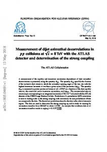
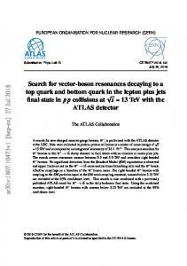
4. OPTICS D. Wang discussed the lattice design of the electron ring of eRHIC [43]. The goals of this project include an electron beam energy of 5-10 GeV, a luminosity of 10321033 cm-2s-1 for ep collisions and of 1030-1031 cm-2s-1 for eAu collisions. The eRHIC is conceived as a ring-ring collider based on RHIC, augmented by a new electron ring, which has a three time smaller circumference. Both beams will be polarized. Electrons may be generated from a polarized source. If instead of electrons, positrons are stored in this ring, they will be polarized by synchrotron radiation at 10 GeV. The product of synchrotron radiation power and radiation time is a constant, which requires a trade off between contradicting requirements. The Sokolov-Ternov polarization time for the present design is 21 minutes. The beam-beam tune shift is higher than in HERA. Round beam collisions become attractive, but have proven difficult to achieve in actual lattice designs, in particular with regard to electron polarization. They remain an option for the future. The last quadrupole, Q1, is placed 0.8 m from the IP. A new quadrupole design was created by B. Parker for a previous optics version with round beams. With round colliding beams a rather large crossing angle of several mrad is required, implying a high voltage for the crab cavities. An anti-symmetric solenoiddipole pair serves as spin rotator between the arc and the IP and it is effective over a wide energy range. The working point is chosen just above the integer to preserve polarization in the ring (the spin tune is near 0.5). For dynamic-aperture computations, the LEGO [44] and SAD [45] codes were used and benchmarked against each other. SAD predicts a larger dynamic aperture than MAD [46]. For the present flat-beam solution, the IR geometry and SR power look feasible. The design optimization is still ongoing. In the subsequent discussion, A. Zholents and others pointed out, as before for C. Montag’s talk, that according to studies by A. Aleksandrov and D. Pestrikov [3] and by K. Hirata and E. Keil [2], the coherent beambeam effects may compromise the performance of unequal-circumference rings. Purportedly, this issue was also investigated by D. Shatilov for the PEP-N project [47]. Similarly, Y. Cai has simulated the performance of a ring-linac collider and he found a 10% effect [48], as is illustrated in Fig. 1. Y. Yan presented the optics diagnostics and correction of beta beating at PEP-II [50] using a model-independent analysis (MIA) [49]. The MIA procedure assumes that the quadrupoles, sextupoles, beam-position monitors (BPMs) etc. are all located at the right locations. It then creates a virtual accelerator by adjusting magnets strengths, BPM calibrations and offsets. The input to MIA are 4 independent high-resolution multi-turn orbits (acquired while exciting either one of the two eigenplanes at two different betaton phases). The extraction of beta functions from the phase advance may break down for a coupled lattice. The optics correction is accomplished by a few knobs containing a limited set of key magnets. Y. Yan pointed out that the ‘real machine responds very well to PSN THS01
6
MIA’. Solenoid errors are fitted by normal and skew quadrupole variables; tilt angles and coupling ellipses are included. The MIA residual error in the interaction region (IR) is larger than that in the arcs. The LER beta beat was easily fixed using the trombone and global skew quadrupoles. The net success rate of MIA so far is 2 out of 3 or 66.67%. The beta beating in the HER still remains for the moment, but a global skew problem (wrong polarity of all skew quadrupoles) could be confirmed. MIA provides a summary page with condensed optics information. Further improvements in MIA may still be needed, in particular for the IR. A similar application of MIA for beta-function measurements is described in [51].
Figure 1: Simulated luminosity as a function of turn number for PEP-II with (lower curve, blue) and without (upper curve, red) an additional ring-linac collision at 60 Hz [Courtesy Y. Cai, unpublished]. The next speaker, F.-J. Decker, discussed orbit bumps in PEP-II for luminosity optimization [52]. In the PEP-II IR there are large BPM offsets of 9-10 mm in magnitude. Each time when this region was steered flat, the performance degraded. The scale of this problem is stupefying. A 0.2 kG skew quadrupole field is known to change the luminosity by 3-5%. This field is equivalent to a 250 micron offset in a sextupole. A 10-mm offset corresponds to 40% of the strength of a regualar quadrupole. The deflection from the sextupole can be stronger than the deflection needed to make a bump. Both the offset in the plane of the bump and the coupled part of the bump, in the orthogonal plane, must be closed. Bumps introduced at high current in certain regions of the PEP-II LER could result in more than 20% increase of luminosity [53]. Electron cloud or wake field were invoked as possible explanations. It was not a non-linear problem, as the region in question contained neither sextupoles nor skew quadrupoles. Another suggestion is that the effect might have been caused by the change in path length induced by the bump. F.-J. Decker speculated that for the present optics and tune it might be possible to steer the orbit flat all around the machine and then introduce special
e+e- Factories’03, Stanford, October 13-16, 2003 bumps to optimize the luminosity. A “short-cut” in the chicane due to the bumps may have changed the horizontal offset in the sextupoles all around the machine. The optimum amplitude of a bump often is “one-sided”, which means the luminosity decreases steeply in one direction and is flat in the other. The bumps seem to have less effect after the tune was moved to the ½ integer. Other, unwanted bumps are generated by the global orbit feedback (GOF). Sometimes these accidental bumps became as large as 17 mm, at one point causing a vacuum leak. D. Rice suggested that the effect of the bumps could be related to dispersion in the rf cavities and to the excitation or compensation of synchro-betatron resonances. It was proposed to systematically explore the effect of localized bumps all around the PEP-II ring. The final three talks by A. Gallo, J. Seeman and J. Gao were held in a joint session with the working group on rf, feedback, and collective feedbacks, chaired by J. Corlett, who was assisted by D. Teytelman and P. McIntosh. A. Gallo presented the innovative concept of strong rf focusing [54]. The desire to reduce the length of the bunches is motivated by the fact that the luminosity scales roughly as the inverse bunch length, due to the hourglass effect. Unfortunately, for short bunches one easily reaches the microwave threshold (Boussard criterion). The standard approach to generate short bunches requires a very high RF voltage and a small impedance. Strong RF focusing represents a promising alternative, which may also avoid the microwave instability, likely encountered for short bunch lengths. This scheme resembles a magnetic bunch compressor. The synchrotron tune is close to the ½ integer resonance. Optimum values for longitudinal beta functions, bunch length at the IP, energy spread, rf voltage and wave length are easily determined. The bunch length is not constant during one turn, but varies dramatically around the ring, assuming a minimum at the collision point. Wake field sources are preferably located near the rf, on the opposite side from the IP. The rf energy acceptance must be reconsidered. For the contemplated DAFNE2 upgrade, the energy acceptance is 1.1% at the IP and 0.45% at the rf. The variation of the acceptance and bunch length around the ring must be taken into account for Touschek and IBS calculations. The wake potentials depend strongly on the bunch length, often as the third inverse power. The sign of the momentum compaction is important for the onset of instability. A proposed ‘wiggling’ machine is constructed by adding inverse bends. This design can achieve a 2 mm bunch length for DAFNE2. A bunch length of 1mm would require a more exotic lattice. There are not many free parameters left. RF frequencies above 500 MHz are not suitable, since they would imply too low an energy acceptance. It is perhaps worth to be mentioned that as early as 1969 the longitudinal motion in electron storage rings for large synchrotron tunes was studied by A. Piwinski [55], who already derived expressions for the variation of bunch length and energy spread around the ring. J. Seeman next outlined the future very high luminosity options for PEP-II [56]. His extrapolation is based on the PSN THS01
experience from the present PEP-II and KEKB, namely that asymmetric beam energies work, and that beam-beam tune shifts of 0.08-0.10 can be reached. The PEP-II luminosity will be increased by storing 4 times more bunches (bunch spacing 0.6 ns), by increasing the bunch current 2 or 3 times, and by accepting 50% larger tune shifts, which can be sustained with continuous injection. In addition the vertical beta function will be decreased by a factor 2-3 down to 1.5-3 mm. A bunch-by-bunch feedback system operating at a sub-ns time scale will be necessary. It has already been designed by the group of J. Fox and its components are being prototyped. The beam energy asymmetry is decreased in order to save beam power. For fiscal year 2008, beam currents of 4.5 A positrons and 2 A electrons appear within reach, with a vertical IP beta function of 6 mm, and every 2nd RF bucket filled. This can provide a luminosity of 2-3x1034 cm-2 s-1, but the particle physicists are asking for 1036 cm-2 s-1. Higher luminosity is accomplished as follows. The HER energy is decreased from 9 to 8 GeV, and the HER current is ramped up to 4.8 A. The LER energy is increased from 3 to 3.5 GeV, which requires a new vacuum chamber for the LER. The LER current will be 11 A. The SR flux in the LER can be softened by adding bending magnets and by increasing the magnet bore. The number of bunches will be 3400, the vertical beta function at the IP 2.2 mm, and the beambeam tune shift 0.15. The corresponding site power is 120 MW, supporting a luminosity 5x1035 cm-2s-1. An advanced upgrade option foresees a new RF frequency, e.g., 952 MHz, and more bunches. With 1.8 mm bunch length, a crossing angle of 15 mrad, 6900 bunches, and βy*=1.5 mm, the luminosity becomes 1036 cm-2s-1, still for a 120 MW site power. J. Seeman showed an intriguing plot of site power versus luminosity for the two RF frequencies, clearly revealing a substantial gain by the 952 MHz system. The steep increase of either curve at a certain power level indicates a fundamental limitation, which he baptized the ‘Rice limit’ after David Rice. He pointed out that further issues related to high luminosity factories and the particle physics at such machines will be discussed in an upcoming KEK-SLAC workshop at Oahu, Hawaii, mid-January 2004. The last talk by J. Gao on the analytical treatment of nonlinear beam dynamics [57] extended the approach of his earlier presentation [22] so as to include the effects of wigglers, space charge and electron cloud on the dynamic aperture. For the wigglers, he illustrated his calculations with the example of Super-ACO. Similar to the beambeam tune-shift limit derived in [22] he computed a limit from the space-charge effect, choosing the TESLA damping ring as a prominent example. The combined effect of the electron cloud and the beam-beam interaction was treated in an analogous way. J. Gao’s result suggests a further reduction of the beam-beam dynamic aperture due to the electron cloud. Considering PEP-II, he computed that the beam-beam tune shift limit would be reduced from 0.045 to 0.01 by the electron cloud. Everybody agreed with his final conclusion that analytical treatments are helpful in addition to numerical simulations.
e+e- Factories’03, Stanford, October 13-16, 2003
5.
DISCUSSION
The working group was asked to respond to several charges (shown in bold italics below), and arrived at the following answers. Explore and document the operational experience of present interaction regions. Can interation regions with a βy* of 2-3 mm be designed? Evaluate procedures for measuring and controlling IP optics parameters. These questions were only partially answered, though in lively discussions. The working group considered achieving the short bunch length of 2-3 mm for future colliders to be the real challenge, which includes the generation of such bunches, the associated higher-order mode power, the bunch lengthening, CSR instability, and Touschek lifetime. A related set of challenges concerns the IR itself. The IR limits the bunch length, due to HOM heating of critical components, and it limits the IP beta function, due to the restricted apertures. The IR also greatly affects the optics modelling, the optics tuning, coupling and diagnostics, which have been a problem for both PEP-II and DAFNE. The question was asked what the right balance is between hardware solutions and software modelling, e.g., a more modular and more expensive IR might allow more precise modelling and a better optics control. It was proposed to seriously consider the Raimondi-Seryi IR layout for the next round of factory upgrades. The first step in this direction would be to design a prototype optics, with truly local chromatic correction, and compare its dynamic aperture with that of a conventional layout. A. Seryi expressed interest in pursuing this type of solution. The effect of the possible slope of the IP dispersion function should be studied as well in beam-beam simulations, and Y. Cai will likely take on this enterprise for PEP-II. What are the present limits of the beam-beam interaction? The working group came up with a long list of limitations, which comprises the damping, bunch shapes (F.-J. Decker suggested to create a transversely uniform bunch to remove beam-beam nonlinearities), bunch length, beam lifetime, lattice nonlinearities, IP tuning, coupling, the vertical IP beta function, parasitic crossings, crossing angle, travelling focus (J. Gao), and electron cloud. Trade-off between parasitic collisions and crossing angle? Head-on collision are difficult to realize with short bunch spacings, due to the strength of parasitic collisions. It was debated whether there exists a limit on the Piwinski angle, as possibly suggested by some of the strong-strong beambeam simulations. To find the optimum parameter choice, the dependence of the specific luminosity on the bunch spacing shoud be studied. M. Placidi proposed to collect data for various colliders (PEP-II, KEKB, DAFNE) and to see, whether they suggest a scaling law; if the optimum number of bunches is not too large, perhaps the crossing angle and parasitic collisions can be entirely avoided in a certain range of parameters. It was proposed to benchmark the strong-strong simulations suggesting a dramatic effect PSN THS01
8
of the crossing angle against data from an actual machine, e.g., DAFNE, where the crossing angle might be varied between 10 and 20 mrad and the bunch length could be changed by a 3rd harmonic RF system. J. Gao asked about experience with, or considerations on, the pinch effect in storage rings. He pointed to a paper by A. Chao [58]. It was remarked that P. Chen’s and K. Yokoya’s work [59] might be relevant for this question as well. The pinch effect appears similar to the notion of a travelling focus in linear colliders [60]. The audience and J. Gao raised three questions: (1) Is it important? (2) Can it be useful? (3) How does it scale with energy? What are the next steps in understanding the beam-beam interaction and how to increase the tune shifts? The next step is an extension of strong-strong beam-beam simulations so as to include the parasitic collisions, and to determine the optimum crossing angle for a given bunch spacing. K. Ohmi and Y. Cai will rise to this challenge. The tune shifts could be increased by a variety of means: RF focusing, crab cavities, round beams in conjunction with an improved dynamic aperture, wire compensation of the parasitic collisions, electron lens, or two collision points with mutual cancellation. It was next debated whether and where the strong RF focusing idea could be tested in practice. A meaningful experiment should approach a synchrotron tune near 0.5. For CESR the maximum synchrotron tune is 0.1-0.2 at 1.5 GeV, while the DAFNE2 design value is 0.4. Some other candidate storage rings that came to mind are the SLAC damping ring, PETRA, DORIS, or the new SPEAR-III. During the 2000 Chamonix workshop, such test was proposed for LEP at injection by A. Hofmann, but, unfortunately, LEP no longer is available. Are there new operational issues that can help control beam tails and backgrounds? Octupoles are not useful for increasing the tune shift (J. Seeman tried them unsuccessfully at CESR and SPEAR), but at DAFNE the octupoles help for lifetime and background. Specifically, they increase the beam lifetime by about 20%. Finally, the electron cloud was also discussed, in particular the question why DAFNE does not observe any electron-cloud effects. The DAFNE bunch spacing is 80 cm, the bunch current 20 mA, and the bunch population about 4x10¹⁰. It was suggested that DAFNE should try to produce an electron cloud, by reducing the number of bunches, increasing the bunch population, e.g., by a factor of 2, and possibly filling every RF bucket. The situation at CESR was also discussed. There the bunch spacing is 3.6 m, or 12 ns, and for normal operation up to 5 bunches are stored in a row (‘mini-trains’). For a dedicated study, an arbitrary number of positron bunches could be produced in CESR, and bunch populations of 3x10¹¹ are feasible. CESR has an Al beam-pipe without an antechamber. D. Rice suggested, for future reference, to compile a list of all existing strong-strong beam-beam simulation codes, including their main features and possible benchmarks against operating colliders or other simulation programs.
e+e- Factories’03, Stanford, October 13-16, 2003 This compilation is displayed in Table 1. Some related references are [14,17,61,62,63,64,65,66]. Table 1:Strong-Strong Beam-Beam Simulation Codes
6. CONCLUSIONS For the next generation of factories several exciting novel design concepts have been proposed. Most of these will likely be tested soon, such as strong RF focusing, round-beam collisions, Raimondi-Seryi final focus for factories, beam-beam compensation schemes, etc. Significant progress is visible not only in the experimental beam-beam diagnostics, but also in the strong-strong beam-beam modeling, where simulations now closely reproduce observed luminosities and limiting tune shifts, and where, for typical optimized working points, the main limitation seems to arise from an incoherent effect. A few open questions still remain to be answered, such as the optimum choice of crossing angle or bunch spacing, and the best approach to produce a short bunch length. The present IR layouts work well. They provide a solid basis for the upgrades. Interesting news were also reported on lattice designs, optics diagnostics, tuning, and magnet motion. In summary, the progress at the operating electron-positron colliders is impressive, as evidenced by the recent remarkable improvements in their performance and understanding. The factories community has all reason to look optimistically towards the future.
Acknowledgments I would like to thank John Seeman for inviting me to chair this working group, my associates Michael Sullivan and Yunhai Cai for their precious help in organizing and managing the sessions, and John Corlett for the fruitful collaboration with the rf working group. I also thank Yunhai Cai and Kazuhito Ohmi for helpful informations.
References [1] C. Montag, “eRHIC Interaction Region Design,” these proceedings. [2] K.Hirata, E.Keil, “Barycentre Motion of Beams due to Beam-Beam Interaction in Asymmetric Ring Colliders,’’ NIM A292, 156-168 (1990). PSN THS01
[3] A.Aleksandrov, D.Pestrikov, “Coherent Beam-Beam Oscillations in Asymmetric Colliders,’’ EPAC90, Nice (1990). [4] M.Sullivan, “Upgrades to the PEP-II Interaction Region,” these proceedings. [5] A. Seryi, “PEP-II IR Alignment,” these proceedings. [6] M.Sullivan, “Super-B Factory Interaction Regions,” these proceedings. [7] Y.Funakoshi, “IR Design for Super-KEKB,” these proceedings. [8] F.Zimmermann, “Raimondi-Seryi Final Focus for e+eFactories?,” these proceedings. [9] P.Raimondi, A. Seryi, “A Novel Final-Focus Design for Future Linear Colliders,” Phys. Rev. Lett. 86, pp. 3779 (2001). [10] P.Raimondi, F. Zimmermann, “Performance of a Compact Final-Focus System for a 30-TeV Muon Collider,” CERN-SL-Note-2001-020 AP; contribution to the ‘6-Month Feasibility Study on High Energy Muon Colliders,’ A.Caldwell, B.King (eds.), ISBN: 1-58949-020-7, Rinton Press (2001). [11] A.Valishev, “Simulations of Beam-Beam Interaction for Round Beams,” these proceedings. [12] E.Young et al., “Collisions of Resonantly Coupled Round Beams at the Cornell Electron-Positron Storage Ring (CESR),” PAC 97 Vancouver (1997). [13] D.Shatilov, “Beam-Beam Simulations at Large Amplitudes and Lifetime Determination,” Part. Accel. 52, pp. 65-93 (1996). [14] K.Ohmi, “Simulation of Beam-Beam Effects in a Circular e+e- Collider,” Phys. Rev. E, 62, pp. 72877294 (2000). [15] A.Skrinsky, “New Colliders at Novosibirsk,” these proceedings. [16] Y.Cai, “Beam-Beam Simulation for PEP-II,” these proceedings. [17] Y.Cai et al., “Simulation of the Beam-Beam Effects in e+e- Storage Rings with a Method of Reducing the Region of Mesh,” PRST-AB 4, 011001 (2001). [18] K. Hirata, F. Ruggiero, “Treatment of Radiation in Electron Storage Rings,” LEP Note 611 (1988). [19] A.V. Otboyev, E.A. Perevedentsev, “Self-Consistent Beta Functions and Emittances of Round Colliding Beams,” PRST-AB 2, 104401 (1999). [20] K.Hirata, “Analysis of Beam-Beam Interactions with a Large Crossing Angle,” Phys. Rev. Letters 74, 12, p. 2228 (1995). [21] J.Gao, “Analytical Estimation of Beam-Beam Interaction Limited Lifetimes in Circular Colliders,” these proceedings. [22] J.Gao, “Analytical Estimation of the Beam-Beam Interaction Limited Dynamic Apertures and Lifetimes in e+e- Circular Colliders,” NIM A 463, pp. 50-61 (2001). [23] C.Biscari, “Negative Alfa Experience,” these proceedings. [24] W.Kozanecki, “Beam-Beam Experience at PEP-II,” these proceedings.
e+e- Factories’03, Stanford, October 13-16, 2003 [25] K.Ohmi, “Beam-Beam Limit Estimated by QuasiStrong Simulation,” these proceedings. [26] K.Ohmi, K.Hirata, N.Toge, “Quasi-Strong-Strong Simulations for Beam-Beam Interactions in KEKB,” Proc. 5th EPAC, Sitges (1996). [27] K.Ohmi, “Summary of Beam-Beam Effects,” these proceedings. [28] J.Tennyson, “Resonance Transport in Near-Integrable Systems with Many Degrees of Freedom,” Physica 5D, 123-135 (1982). [29] F.Zimmermann, “Weak-Strong Model for the Combined Effect of Beam-Beam Interaction and Electron Cloud,” these proceedings. [30] G.Rumolo and F.Zimmermann, “Electron Cloud Instability with Space Charge and Beam Beam,” Int. Workshop on Two-Stream Instabilities, KEK, Tsukuba, 2001, and CERN-SL-2001-067 (2001). [31] G.Rumolo and F.Zimmermann, “Practical User Guide for HEADTAIL,” CERN-SL-Note-2002-036 AP (2002). [32] A.Chao, “Physics of Collective Beam Instabilities in High Energy Accelerators,” J. Wiley (1993). [33] M.Biagini, “Long-Range Beam-Beam Interactions in PEP-II,” these proceedings. [34] F.Zimmermann, “Compensating Parasitic Collisions using Electro-Magnetic Lenses,” these proceedings. [35] J.-P.Koutchouk, “Principle of a Correction of the Long-Range Beam-Beam Effect in LHC using Electromagnetic Lenses,” LHC Project Note 223 (2000); Proc. PAC2001 Chicago, p.1681 (2001). [36] F.Zimmermann, “Weak-Strong Simulation Studies for the LHC Long-Range Beam-Beam Compensation,” in ‘Contributions of the SL Division to the Workshop on Beam-Beam Effects at Fermilab’, LHC Project Report 502 (2001). [37] J.Irwin, “Diffusive Losses from SSC Particle Bunches due to Long-Range Beam-Beam Interactions,” SSC-233 (1989). [38] F.Zimmermann, “Short Review of Super-Bunches for Hadron Colliders,” these proceedings. [39] K.Takayama et al., “Superbunch Hadron Colliders,” PRL 88: 144801 (2002). [40] F.Ruggiero, G.Rumolo, F.Zimmermann, Y.Papaphilippou, “Beam Dynamics Studies for Uniform Hollow) Bunches or Super-Bunches in the LHC: Beam-Beam Effects, Electron Cloud, Longitudinal Dynamics, and Intrabeam Scattering,” Proc. RPIA2002 Tsukuba, and CERN LHC Project Report 627 (2003); see also the same authors at PAC2003 Portland, Oregon (2003). [41] O.Bruning et al., “LHC Luminosity and Energy Upgrade: A Feasibility Study,” CERN LHC Project Report 626 (2002). [42] F.Ruggiero, F.Zimmermann, “Luminosity Optimization near the Beam-Beam Limit by Increasing Bunch Length or Crossing Angle,” PRST-AB 5:061101 (2002). [43] D.Wang, “Lattice Design of the Electron Ring of eRHIC,” these proceedings. PSN THS01
10
[44] Y.Cai, “LEGO: A Class Library for Accelerator Design and Simulation,” ICAP98 Monterey, eConf C980914:6-10 (1998). [45] “SAD: Strategic Accelerator Design”, home page http://acc-physics.kek.jp/SAD/sad.html [46] H.Grote, C.Iselin, “The MAD Program (Methodical Accelerator Design) Version 8.4: User’s Reference Manual,” CERN-SL-90-13-AP-REV.2 (1991). [47] D. Shatilov, “Beam-Beam Study for PEP-N Project,” comment by J. Seeman (no reference provided). [48] Y.Cai, “Beam-Beam Simulations for a Linac-Ring Collider,” unpublished. [49] J.Irwin, C.X.Wang, Y.Yan, et al., “ModelIndependent Beam Dynamics Analysis,” Phys. Rev. Letters 82: 1684-1687 (1999). [50] Y. Yan, “PEP-II Beta-Beat Fixes with MIA,” these proceedings. [51] C.-X.Wang, et al., “Phase Advance and Beta Function Measurements using Model-Independent Analysis,” PRST-AB 6, 104001 (2003). [52] F.-J.Decker, “Orbit Bumps in PEP-II to Maximize Luminosity,” these proceedings. [53] F.-J.Decker, et al., Orbit Distortions and Bumps in the PEP-II LER Ring,” EPAC’02 Paris, p. 289 (2002). [54] A.Gallo, “Strong RF Focusing: a Possible Approach to Get Short Bunches at the IP,” these proceedings. [55] A.Piwinski, “Synchrotron Oscillations in HighEnergy Synchrotrons,” NIM 72, pp. 79-81 (1969). [56] J.Seeman, “Future Very High Luminosity Options for PEP-II,” these proceedings. [57] J.Gao, “Analytical Treatment of Nonlinear Beam Dynamics,” these proceedings. [58] A.W.Chao, Y.Kamiya, “Bunch Shape at IP and the Pinch Effect,” SLAC-CN-218 (1983). [59] K.Yokoya, P.Chen, “Beam-Beam Phenomena in Linear Colliders,” 1990 US-CERN School, Hilton Head Island, So. Carolina (1990). [60] V. Balakin, “Traveling Focus Regime for Linear Collider VLEPP,” Proc. LC91 workshop on Linear Colliders, Protvino 1991, Vol. 1, p. 330 (1991). [61] S. Krishnagopal, R. Siemann, “Coherent Beam-Beam Interactions in Electron-Positron Colliders,” PRL 67, 18, p. 2461 (1991). [62] J. Qiang, et al., “Strong-Strong Beam-Beam Simulation using a Green Function Approach,” PRST-AB 5: 104402 (2002). [63] W. Herr, M.P. Zorzano, F. Jones, “A Hybrid Fast Multipole Method Applied to Beam-Beam Collisions in the Strong-Strong Regime,” PRST-AB 4: 054402 (2001). [64] J. Shi, D. Yao, “Colective Beam-Beam Effecst in Hadron Colliders,” PRE62, 1258-1265 (2000). [65] A. Kabel, “Parallel Simulation Algorithms for the 3Dimensional Strong-Strong Beam-Beam Interaction,” PAC2003 Portland Oregon (2003). [66] E.B. Anderson, J. Rogers, “ODYSSEUS: A Dynamic Strong-Strong Beam-Beam Simulation for Storage Rings,” ICAP98 Monterey, eConf C980914:122126 (1998).
e+e- Factories’03, Stanford, October 13-16, 2003
Brief Review of Super-Bunches for Hadron Colliders F. Zimmermann CERN, 1211 Geneva 23, Switzerland Cancellations in the beam-beam force (1) between two collision points with alternating planes of beam crossing, (2) for a uniform longitudinal bunch profile, and (3) when operating in a regime of large Piwinski angle or, alternatively, with long super-bunches allow for significant increases in hadrom-collider luminosity. The relevant expressions for beam-beam tune shifts and luminosity are revisited. The results are illustrated by considering possible upgrades of the Large Hadron Collider.
1. HISTORY AND MOTIVATION The CERN Intersecting Storage Rings (ISR) were the first hadron collider. It stored coasting (unbunched) proton beams with currents up to 50 A and it reached a peak luminosity of 1.4x1032 cm-2s-1. Despite of 25 years which have passed since, this performance has not yet been achieved by any other hadron collider, as illustrated in Table 1.
by colliding the beams at two interaction points with alternating planes of crossing, (2) the absence of PACMAN bunches otherwise existent at the end of a bunch train, and (3) the avoidance of beam-induced multipacting and electron-cloud build up. Table 2: Parameters for the nominal and the ultimate LHC, and for three possible upgrades [2].
Table 1: Commissioning year, beam energy and peak luminosity of all hadron colliders. The Large Hadron Collider (LHC) is still under construction and the LHC upgrade (LHC-II) in the early design phase.
2. TUNE SHIFT
ISR-style quasi-coasting beams were recently identified as a key ingredient for future highest-energy highluminosity proton colliders (see, e.g., Ref. [1]). In particular, a possible upgrade of the CERN Large Hadron Collider (LHC) can be considered by operating not exactly with coasting beams, but with long “super-bunches”, which are confined, e.g., by a barrier bucket rf system [2]. As an illustration, Table 2 compares the nominal and ultimate LHC design parameters with three possible upgrades. The last column shows the pure super-bunch upgrade, while the second-to-last column displays an alternative parameter set, where the number of bunches remains nominal, and only the bunch line density and crossing angle are increased (the second set of numbers in this row refer to ‘hollow’ or ‘flat’ bunches with a uniform longitudinal profile, which, for the same beam-beam tune shift, offer 30-40% higher luminosity than bunches of Gaussian shape). The main advantages of long or “super-bunches” are (1) a cancellation between the head-on and ‘long-range’ components of the beam-beam tune shift, which is realized PSN WGA19
The cancellation between head-on and ‘long-range’ components is evident from the formulae for the horizontal and vertical tune shifts for a single interaction point (IP) with horizontal crossing angle [3]:
∆Q x =
l/2 λr p β * 1 + cos θ s2 × + θ cos 1 *2 ∫ πγ 2 β −l / 2 s 2 sin 2 θ 1 (1) − − 1 exp 2 s 2 sin 2 θ 2 σ
s 2 sin 2 θ 1 ds − exp − 2σ 2 σ 2 λr p β * 1 + cosθ l / 2 s2 ∆Q y = − ∫ 1 + *2 × πγ 2 −l / 2 β s 2 sin 2 θ 1 ds (2) − 1 exp − 2 s 2 sin 2 θ 2 σ where σ = σ ( s ) = σ * 1 + s 2 / β *2 ,
e+e- Factories’03, Stanford, October 13-16, 2003
σ * = β * ε = β * ε N / γ , and ε denotes the geometric transverse emittance. Except for the last term in (1), the expressions (1) and (2) are nearly identical and of opposite sign. In case of a vertical crossing, the expressions for the two planes are interchanged. Therefore, by colliding the two beams at two interaction points with alternating crossing, the absolute value of the tune shift in both planes is identical and much smaller than that for a single IP. The same cancellation is also achieved, already for a single IP, if the beams are collided in a crossing plane tilted at 45o or 135o [4,5], which, however, may introduce betatron coupling. Figure 1 shows a schematic of a super-bunch hadron collider with alternating crossing at two IPs.
2
and can then express the total tune shift for two IPs as [5] (Gauss ) ∆Qtot = ∆Qx + ∆Qy
=−
s2 λβ *rp 1+ cosθ l / 2 ds 1 + ∫ 2 −l / 2 β *2 πγ
1 − cosθ 2 2 s sin θ
2 2 1 − exp − s sin2 θ 2σ
(4)
s 2 sin 2 θ cosθ + exp − 2σ 2 σ 2 +
s 2 sin 2 θ 1 − exp − g ( s), 2σ 2
1 + cosθ σz 2
The expressions (3) and (4) simplify greatly, if we make a number of simplifying assumptions. For the case of Gaussian bunches, we consider the limit of a small crossing angle, i.e., θ > 1 [3]. Under the above assumptions, the tune shift for Gaussian bunches, Eq. (4), can be written as
Figure 1: Schematic of a super-bunch hadron collider with alternating crossing at two collision points [6].
(Gauss ) ∆Qtot ≈
Nbrpβ * 2πγσ * σ *2 +θ 2σz 2 / 4
2 rpβ * ∧ ≈ λ, π γσ * θ
3. OPTIMUM LUMINOSITY
(5)
As shown in Ref. [3], the luminosity of a conventional hadron collider operating with round bunched Gaussian beams can be increased in proportion to the bunch current, while keeping a constant beam-beam tune shift, by increasing the product of bunch length and crossing angle. If the longitudinal profile is made uniform instead of
where λ denotes the peak line density, and the luminosity of Gaussian bunches simplifies to
Gaussian an additional factor of 2 is gained [5,7]. Indeed, the total tune shift for flat (uniform) profiles is given by [5]
Combining the last two expressions, the luminosity for Gaussian bunches becomes [3,5,6]
∆Qtot( flat ) = ∆Qx + ∆Qy
=
(3)
s 2 sin 2 θ cosθ − exp − ds 2σ 2 σ 2 In the case of Gaussian bunches we define the form factor
s 2 (1 + cosθ ) 2 , g ( s ) = exp − 2σz PSN WGA19
LGauss ≈
fcollNb 2 4πσ * σ *2 +θ 2σz 2 / 4
≈
fcollNb 2 (6) 2πσ *θσz
θ 2σ z2 fcollγε N 2 π 1 Q ∆ + tot rp 2 β * 4σ *2 fcollγε 2 πθσ z ≈ 2 N ∆Qtot 2σ * rp β *
LGauss ≈
λβ *rp 1+ cosθ l / 2 s2 × 1 + ∫ πγ 2 −l / 2 β *2
cosθ − 1 s 2 sin 2 θ 2 2 1 − exp − 2σ 2 θ s sin
∧
(7)
which explicitly shows that, for a constant total tune shift, the luminosity increases in proportion to θσz. For the case of uniform super-bunches, we also consider a small crossing angle, θ > ε / β * , and that the total bunch
length l flat is larger than the effective length of the interaction region, or l flat > 10σ * / θ .
e+e- Factories’03, Stanford, October 13-16, 2003 The total tune shift for super-bunches, Eq. (3), then reduces to
∆Q
≈−
( flat ) tot
≈−
λrp 2
*
γ π λrp 2 πγ
β *γ 1 lθ Erf εn θ 2 2σ * (8) 2 rpβ * β *γ 1 λ ≈ εn θ π γσ *θ
and the luminosity to
L flat ≈
f coll l flat λγ λ × 2π εn
ldet /( 2 β *)
β *2 θ 2 u 2 1 exp du (9) − 2 2 2 ∫ 1 σ + u + u 4 * 1 −ldet /( 2 β *) f coll l flat λ2 1 θ π
≈
1
β *εn / γ
.
Combining the last two equations, we get an expression similar to (7) for Gaussian bunches, namely [5,7]
L flat ≈
fcollγεn π θlflat ∆Qtot2 2 rp β * 2σ *
(10)
which is proportional to the crossing angle θ and to the total length of the super-bunch lflat. More succinctly, for the purpose of comparison, we can also express the luminosities in terms of the total tune shift and the total bunch population Nb. For Gaussian bunches we obtain [5,7]
LGauss ≈
1 fcollγ ∆Qtot N b 2 rp β *
(11)
and for super-bunches with a uniform profile
L flat ≈
1 fcollγ ∆Qtot N b 2 rp β *
4. CONCLUSIONS By colliding either bunches with a large Piwinski angle or long super-bunches, the LHC luminosity can be increased about 10 times to 1035 cm-2s-1 for the same total tune shift as in the ‘ultimate’ design and only moderately increased total beam current. Problems expected to arise in the nominal LHC due to PACMAN bunches [9] and electron cloud would be solved simultaneously, if superbunches are employed [5,7].
Acknowledgement (12)
As indicated already in Table 2, a factor of about
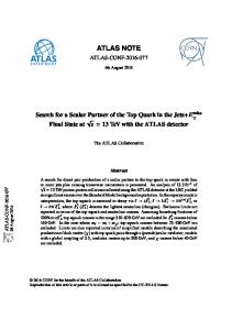
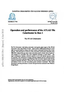
2 increase in luminosity is gained as well, if we simply replace the Gaussian profile of a bunched beam by a flat uniform longitudinal shape, as long as we operate in the regime of a large Piwinski angle. Flat or ‘hollow’ bunches can be generated by radiofrequency gymnastics in the CERN PS booster and they are already available from the LHC injector chain [8]. As an example for the usefulness of the above formulae, Fig. 2 shows the possible luminosity gain in the LHC that can be achieved by increasing the Piwinski angle with bunches of either Gaussian or uniform profile.
PSN WGA19
Figure 2: Relative luminosity gain for the Large Hadron Collider as a function of relative increase in crossing angle or bunch length for a uniform bunch profile or superbunches (top) and for regular Gaussian bunches (bottom). The vertical axis is normalized to a base luminosity at the beam-beam limit with two IPs of L0=2.3x1034 cm-2s-1 and the horizontal axis to an rms bunch length of σz0=7.6 cm or to a crossing angle θ0=300 µrad [5,7].
I thank J. Seeman for suggesting this presentation.
e+e- Factories’03, Stanford, October 13-16, 2003
References [1] K. Takayama et al., “Superbunch Hadron Colliders,” Phys. Rev. Lett. 88,144801 (2002). [2] O. Bruning et al., “LHC Luminosity and Energy Upgrade: A Feasibility Study,” edited by F. Ruggiero, CERN LHC Project Report 626 (2002). [3] F. Ruggiero, F. Zimmermann, “Luminosity Optimization Near the Beam-Beam Limit by Increasing Bunch Length or Crossing Angle,” PRST-AB 5, 061001 (2001). [4] Y. Shimosaki, “Beam Beam Effects in the Inclined Super-Bunch Crossing,” Proc. Int. Workshop on Recent Progress of Induction Accelerators (RPIA2002), Tsukuba, Japan, October 2002, KEK Proceedings 2002-30, pp. 126-130 (2002). [5] F. Ruggiero, F. Zimmermann, G. Rumolo, Y. Papaphilippou, “Beam Dynamics Studies for Uniform (Hollow) Bunches or Superbunches in the
PSN WGA19
4
LHC: Beam-Beam Effects, Electron Cloud, Longitudinal Dynamics, and Intrabeam Scattering,” RPIA2002 Tsukuba (2002). [6] K. Takayama, Talk on a Superbunch VLHC at the Hadron Colliders Working Group, Snowmass 2001. [7] F. Ruggiero, F. Zimmermann, G. Rumolo, Y. Papaphilippou, “Beam-Beam Interaction, Electron Cloud and Intrabeam Scattering for Proton SuperBunches,” PAC2003 Portland (2003). [8] C. Carli, M. Chanel, “New Methods to Create Hollow Bunches,” Proc. 20th ICFA Advanced Beam Dynamics Workshop on High Intensity High Brightness Hadron Beams, Fermilab, April 2002, CERN/PS 2002-035 (2002). [9] W. Herr, “Effects of PACMAN Bunches in the LHC,” CERN-LHC-Project-Report-039 (1996).
e+e- Factories’03, Stanford, October 13-16, 2003
Raimondi-Seryi Final Focus for e+e- Factories? F. Zimmermann CERN, 1211 Geneva 23, Switzerland A compact final-focus system with a local chromatic correction would likely improve the performance of factory upgrades.
1. MOTIVATION Two primary challenges encountered in B factory upgrade designs are the need to place stronger quadrupoles closer to the IP and a limited dynamic aperture, both of which are closely linked to the reduction of βy* at the collision point. In this article I attempt to revive interest in an alternative final focus that, until now, does not appear to have drawn an adequate attention from the factories community.
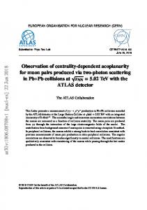
2. DESIGN HISTORY In 2000, P. Raimondi and A. Seryi revolutionized the final-focus design for linear colliders, by proposing a new compact final-focus system [1], which offers a number of distinctive advantages compared with earlier design concepts. Since then, the NLC and CLIC linear collider designs have adopted the new type of final focus, and a compact optics for TESLA is being worked on [2]. A prototype final-focus system of the Raimondi-Seryi type was also designed by S. Kuroda for the ATF-2 project at KEK [3]. The conceptual difference between the new and old concepts was vividly illustrated by N. Walker [4], whose schematics we reproduce in Fig. 1.
The compact system features a truly local chromatic correction where the sextupoles are placed next to the final low-beta quadrupoles. The nonzero dispersion then required in this region either translates into a nonzero slope of dispersion at the interaction point (IP) [1] or it could be generated – or rather cancelled – by a downstream dipole magnet, such as the permanent dipole B1 in PEP-II. The compact system offers numerous advantages over earlier design schemes, such as an increased momentum bandwidth, much shorter length, fewer and weaker quadrupoles, the possibility of a larger free distance between the last quadrupole and the IP, and an improved dynamic aperture. The only possible disadvantage is the slope of dispersion at the IP, which could drive synchro-betatron resonances. The effect should be similar to that of a crossing angle of size
θ eff =
D /*σ δ
σz
Since the ratio σz/σδ is of order 5-10, the maximum acceptable slope of IP dispersion is 5-10 times larger than the maximum tolerable crossing angle [5] - in case there is a limit on the latter as suggested by some of the strongstrong beam-beam simulations [6]. That the compact system can support an outstanding performance not only for single-pass applications, but for storage rings as well was demonstrated in 2001, when within a single day P. Raimondi designed a system for the highly demanding parameters of a 30-TeV muon collider with a large geometric emittance and an already appreciable amount of synchrotron radiation. Designs of conventional systems for the same parameters either could not be finalized or fell far short of the desired performance. By contrast, the compact optics of Raimondi displayed an excellent performance over multiple turns and, in addition, a huge momentum acceptance [7].
3. THE CHALLENGE
Figure 1: Schematic of the novel compact final focus with truly local chromaticity correction and nonzero slope of dispersion at the interaction point (IP), as developed by P. Raimondi and A. Seryi (top), and of the traditional finalfocus design with a non-local chromatic correction, as pioneered by K. Brown around 1985 (bottom) [4] [N.J. Walker, 2002].
PSN WGA18
Quoting the 2001 hallmark paper by P. Raimondi and A. Seryi [1], it is obvious that “similar design could also be considered for high luminosity factories based on storage rings, where the dynamic aperture could be improved even with very small vertical beta functions at the IP.” Given the overwhelming reception that the compact design has experienced in the linear-collider community, it is surprising that nobody has yet taken up this idea for the factory upgrades. General design recipes for this type of system, at linear colliders, have been published by several authors, e.g., by
e+e- Factories’03, Stanford, October 13-16, 2003 A. Seryi and co-workers [8,9], by J. Urakawa and coworkers [3], and by F. Zimmermann and co-workers [10]. At Nanobeam2002 the confidence in this type of system was so high that any experimental tests prior to the construction of the real final focus were considered ‘not necessary’ [11]. Therefore, I close with two questions: (1) Why are all the upgrade designs, e.g., for PEP-II, KEKB, DAFNE-2, etc., still based on the ancient schemes? (2) Can this workshop make progress towards the first modern factory interaction-region design?
References [1] P. Raimondi, A. Seryi, “Novel Final Focus Design for Future Linear Colliders,” Phys. Rev. Lett. 86, 3779 (2001). [2] O. Napoly, J. Payet, “Designing the TESLA Interaction Region with l*=5 m,” Proc. Nanobeam 2002, Lausanne, CERN-Proceedings-2003-001 (2003). [3] S. Kuroda, J. Urakawa et al., “A Plan of KEK-ATF Final Focus Test Beam Line (ATF2),” Proc. Nanobeam 2002, Lausanne, CERN-Proceedings2003-001 (2003). [4] N.J. Walker, “Beam Delivery Systems for Pedestrians,” Proc. Nanobeam 2002, Lausanne, CERN-Proceedings-2003-001 (2003). [5] A. Seryi, private communication (2003).
PSN WGA18
2
[6] Y. Cai, “Beam-Beam Simulation for PEP-II,” this workshop. [7] P. Raimondi, F. Zimmermann, “Performance of a Compact Final Focus System for a 30-TeV Muon Collider,” CERN-SL-Note-2001-020 (AP), contribution to the ‘6-Month Feasibility on High Energy Muon Colliders,’ October 2000-April 2001, edited by A. Caldwell and B. King, ISBN: 1-58949020-7, Rinton Press (2001). [8] A. Seryi, “Discussion on Recipe for Design of a Compact Final Focus,” Proc. Nanobeam 2002, Lausanne, CERN-Proceedings-2003-001 (2003). [9] A. Seryi, M. Woodley, P. Raimondi, “A Recipe for Linear Collider Final Focus System Design,” PAC2003 Portland Oregon (2003). [10] R. Assmann et al., “Beam Dynamics Studies and Advanced Accelerator Research at CTF-3,” CLICNOTE-549, Proc. Nanobeam 2002, Lausanne, CERN-Proceedings-2003-001 (2003). [11] T. Raubenheimer, “R&D Issues WG3&4,” Talk summarizing the joint discussions of working groups 3 and 4 at Nanobeam 2002 Lausanne; see web site http://icfa-nanobeam.web.cern.ch/icfananobeam/slides/raubenheimer_Nanobeams_WG4_ 09-02.pdf (2002).
e+e- Factories’03, Stanford, October 13-16, 2003
Weak-Strong Model for the Combined Effect of Beam-Beam Interaction and Electron Cloud F. Zimmermann CERN, 1211 Geneva 23, Switzerland I review a weak-strong few-particle model for the combined effect of electron cloud and beam-beam interaction and present some numerical examples for PEP-II and KEKB.
1. INTRODUCTION A number of indications suggest an interplay of the electron cloud and the beam-beam interaction. Both introduce a head-tail wake field and both induce a tune shift which varies along the length of the bunch. There is a strong evidence from weak-strong simulations that the two effects enhance each other, as illustrated in Figs. 1-3 [1].
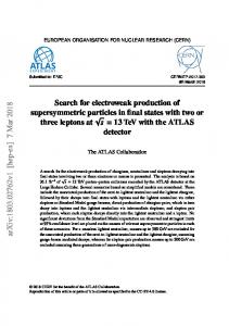
Figure 1: Rms beam size and centroid position along the length of a bunch after 0, 250 and 500 turns in the SPS simulated by the HEADTAIL code [2] for an electron cloud of density ρ=1012 m-3 [1] (G. Rumolo, 2001).
Figure 2: Rms beam size and centroid position along the length of a bunch after 0, 250 and 500 turns in the SPS simulated by the HEADTAIL code [2] for an electron PSN WGA12
cloud of density ρ=1012 m-3 and a rotation around the beam center on each turn representing a collision with an effective beam-beam parameter of ξ=-0.037, held constant [1] (G. Rumolo, 2001).
Figure 3: Rms beam size and centroid position along the length of a bunch after 0, 250 and 500 turns in the SPS simulated by the HEADTAIL code [2] for an electron cloud of density ρ=1012 m-3 and a rotation around the beam center on each turn representing a collision with an effective initial beam-beam parameter of ξ=-0.037, which then varies from turn to turn in accordance with the beamsize evolution [1] (G. Rumolo, 2001). The threshold for the vertical blow up of the positron beam in KEKB and PEP-II is observed to be lower when both effects act simultaneously as compared to the situation when either only the beam-beam collision or only the electron cloud are present. This can be inferred by comparing (1) the specific luminosity attained for a few bunches and the nominal colliding beams, and (2) the vertical beam sizes measured by the synchrotron light monitor in presence and absence of the electron beam, as a function of positron beam current. In this paper I review a weak-strong analysis developed in 2001, which was presented at the Two-Stream Workshop at KEK [1]. This model was inspired by K. Cornelis [3]. It was initially devised to study the combined effect of space charge and electron cloud for the CERN SPS, but the weak-strong model remains the same, if the beam-beam interaction is considered instead of the space charge [1]. Subsequently,
e+e- Factories’03, Stanford, October 13-16, 2003 various strong-strong models for the combined effect of electron cloud and beam-beam interaction were considered by K. Ohmi and A. Chao. These models made partly inconsistent predictions [4].
2
(3,2,1), (2,3,1), (2,1,3), and (1,2,3). The first two of these patterns are illustrated in Fig. 4.
2. MODEL The specific luminosity for different bunch spacings at KEKB suggests that the combined effect of electron-cloud and beam-beam interaction is more harmful than the two phenomena individually. This synergy can be modelled in a weak-strong approximation by a few-particle model, where the electron cloud is represented both by a constant wake field coupling leading and trailing particles and by a linear tune shift along the bunch, and the beam-beam interaction is modelled by an inverse parabolic tune variation with longitudinal distance from the bunch centre. The model was described in Ref. [2]. Below we briefly review the main features. In this model a bunch is represented by a few macroparticles. Two primary effects of the electron cloud are represented, namely the electrons first give rise to a transverse wake between leading and trailing particles, and second to a tune shift which increases roughly linear along the bunch, due to the accumulation of electrons at the transverse beam centre during the passage of the bunch (electron pinch). The beam-beam interaction adds to this a further tune variation, which we approximate by an inversely parabolic dependence on the longitudinal position. Both the electron-cloud tune shift and the beambeam tune shift are referenced to a static coordinate system, thought to be centred at the closed orbit, and not to the centroid position of the macro-particles. The electroncloud wake is considered to be constant, independent of the distance between driving and test particles. Not included in this model is the wake coupling from the beam-beam interaction [5], and neither are any nonlinear transverse forces. In a two-particle model, the variation of the tune with longitudinal position does not yield any instability, while the variation of the tune with momentum error induces the head-tail instability (see [6], page 198). As first suggested by K. Cornelis, to observe an instability from the dependence of the tune on longitudinal position, a minimum number of 3 macro-particles is needed. These particles are taken to be equal in charge and they are distributed uniformly in synchrotron phase space:
ω s z1 = zˆ cos s c ω s 2π z 2 = zˆ cos s + 3 c ω s 4π z3 = zˆ cos s + 3 c The longitudinal ordering of the three particles changes every 6th of a synchrotron period. Listing the leading particle first, the successive patterns are (1,3,2), (3,1,2), PSN WGA12
Figure 4: Schematic of three macro-particles in longitudinal phase space during the first and second 6th of a synchrotron period. The variation of the macro-particle longitudinal position is parametrized as:
z zˆ
ω β ( z ) = ω β ,0 1 − a − b
tune
with
z2 zˆ 2
where a is due to the electron-cloud effect b due to the beam-beam interaction. A positive value of z means the particle is ahead of the bunch centre, and the parameter zˆ denotes the length of the bunch. For the B factories, one has both a>0 and b>0, whereas for the SPS (space charge) or LHC (proton-proton collisions) a>0 and b z j c '' j
where the sum is over all previous bunches, and changes after every 6th of a synchrotron period. We evaluate the motion over the first two sixths of a period. The solutions for the later two thirds are then obtained by simple permutations. We make the usual ansatz of an unperturbed betatron motion, which is multiplied by a slowly varying amplitude ~ yn
yn = ~ y n exp[− iφ n ( s )]
Inserting this ansatz into the equation of motion above and dropping small terms, i.e., second derivatives of ~ y n , we get
e+e- Factories’03, Stanford, October 13-16, 2003
iNr0W0 c ~ ~ y n' ≈ y m exp[− iφ m ( s ) + iφ n ( s )] (1) ∑ 6γCω β m, zm > zn To proceed further, we assume that the phase differences between macro-particles are small, or that |ϕmϕn| ∆t 2
(5)
where the angular brackets denote an average over an ensemble of particles launched at the same nominal action value with radom betatron phases. Since the maximum oscillation amplitude at a location with beta function β is
e+e- Factories’03, Stanford, October 13-16, 2003
yˆ = 2 βI
(6)
the amplitude growth during time ∆t was obtained as
∆yˆ =
β 2I
∆I = 2 D( I )∆t
β yˆ
.
(7)
Figure 9: Simulated amplitude growth in mm during 1 second due to long-range beam-beam collisions in the LHC at injection as a function of starting amplitude. The amplitude growth was inferred from the simulated action diffusion coefficient (∆I ) 2 / ∆t for a typical LHC beta function of β=80 m using (7).
Figure 10: Simulated amplitude growth in mm during 1 second at 55 GeV/c for a 267-A excitation of the SPS wire as a function of starting amplitude. The amplitude growth was inferred from the simulated action diffusion coefficient (∆I ) 2 / ∆t for the beta function at the wire of β=50 m using (7). Comparing Figs. 9 and 10, we note that both reveal a ‘diffusive’ aperture - in one case at about 4.5 mm and in the second case at about 8 mm -, above which the diffusion rate steeply increases. The absolute growth rates outside of the diffusive aperture are also similar, reaching several mm per second in either case.
4
3.3. Overview of Machine Studies A total of six machine experiments were performed in 2002 and 2003. Their main features, objectives and accomplishments are summarized as follows: 1) On 20.08.2002 at 26 GeV/c, we recorded the reading of ion chambers and photo-mulipliers versus the beam position at the wire. A clear threshold was observed. The wire excitation was 120 A, limited by wire-current ripple at higher excitation levels. A tune shift of ∆Qx,y=-/+0.0060 was induced by the wire in the two planes. 2) On 10.09.2002 at 26 GeV/c we commissioned a new inductive coil to suppress current oscillations. The wire temperature increased by more than 18 K at 275 A, in agreement with expectation. We attempted to blow up the transverse emittance by ‘damper chirps’ (with help by W. Hofle). Both tune shift and orbit distortion were recorded as a function of the bump amplitude at the wire for excitation currents of 120 and 267 A. 3) On 23.09.2002 at 55 GeV/c, we again blew up the vertical emittance by the damper. A severe vertical aperture problem was encountered (the physical aperture was much smaller than in previous studies conducted at lower energy, so that the normalized aperture in units of beam sizes was even lower than at 26 GeV/c, defeating the purpose of the increased beam energy). The emittance was observed to shrink due to particle losses for beam-wire distances of less than 12 mm. We recorded beam lifetime and losses as a function of the beam-wire separation. 4) On 27.06.2003 at 26 GeV/c a new dipole was available at the position of the wire, so that the ensuing orbit distortion can be corrected locally. Again particle loss and emittance shrinkage were observed, when the wire was excited. 5) On 04.07.2003 at 26 GeV/c, the emittance was increased by a mismatch in the transfer line. The emittance shrinkage due to particle loss was studied as a function of wire current. 6) On 21.08.2003 at 26 GeV/c, deflecting a small ‘pencil beam’ by a fast kicker, we took transverse turn-by-turn data at all beam-position monitors over the next 1000 revolutions. Then, for a similar beam as in 5) we re-measured the emittance shrinkage, this time as a function of the beam-wire separation. We calibrated the wire scanner signals by mechanical scraping, and we finally attempted to measure the diffusion rate as a function of amplitude by collimator retraction. The important results are further detailed below.
3.4. Linear Optics Perturbations The most direct effects of the wire that can be detected are changes in the linear beam optics, i.e., a closed-orbit
PSN WGA13
e+e- Factories’03, Stanford, October 13-16, 2003 distortion and a change in the two betatron tunes. The shifts in the beam-wire distance d and in the tune Q due to the wire are given by the following two equations:
∆d =
βI w l w rp γec(d + ∆d ) tan(π (Q + ∆Q)) rp I w l w
1 ∆Q = ± 2πγec (d + ∆d ) 2
(8)
where Iw denotes the wire current, lw the wire length, and d the initial beam-wire distance (prior to wire excitation). In principle, the two coupled equations above must be solved together. In practice we found that monitoring either of these two or three (2 tunes) quantities alone provides an accurate and consistent determination of the beam-wire distance with a precision of a few percent. Similar equations would describe the change in orbit and position at the LHC due to the other beam, only that in this case both beams are free to move, while in the SPS experiment the wire position is fixed. The measured changes in the closed-orbit distortion and in the tunes as a function of the beam-wire separation are in excellent agreement with the MAD prediction, as is illustrated in Figs. 11-13.
Figure 11: Closed-orbit deflection angle at the wire either fitted from the nearby BPM readings or predicted by MAD as a function of the beam-wire distance for a wire current of 267 A at 55 GeV/c.
Figure 12: Measured horizontal tune compared with the MAD prediction as a function of the beam-wire distance for a wire current of 267 A at 55 GeV/c.
PSN WGA13
Figure 13: Measured vertical tune compared with the MAD prediction as a function of the beam-wire distance for a wire current of 267 A at 55 GeV/c. Therefore, the beam-wire distance after wire excitation can be inferred from either the tune shift or the orbit change. Example results are plotted in Fig. 14, together with the analytical prediction, as a function of the initial distance for zero wire current.
Figure 14: Actual distance between beam and wire when the wire is excited at 267 A as a function of the initial beam-wire separation without excitation. The upper plotting symbols show distances inferred from the measured tune shift for positive wire current at 55 GeV/c via the first Eq. (8). The lower plotting symbols are distances inferred ) from the measured orbit change for negative wire current at 26 GeV/c using the second Eq. (8). The two dashed blue lines represent the theoretical prediction (8) based on the known step size along the horizontal axis. For the 26 GeV data the zero of the horizontal axis was adjusted such that the right-most point coincided with the prediction. For the 55 GeV/c case no such adjustment was made; instead the horizontal zero point was extrapolated from the orbit readings and the known position of the wire.
3.5. Diffusive Aperture The third machine development (MD) study of 2002 yielded evidence for a threshold in the beam lifetime as a function of the beam-wire separation. This is shown in Fig. 15. When the wire was excited, we observed a steep drop in the beam lifetime, for a beam-wire separation smaller than about 9σ. For 7-8σ separation, the beam lifetime decreased to about 1-5 h due to the wire. We also directly monitored the beam loss by a series of photomultipliers mounted in the vicinity of the beam pipe at strategic locations. If the wire is excited, the beam loss signal, displayed in Fig. 16, exhibits the same sharp threshold as the beam lifetime.
e+e- Factories’03, Stanford, October 13-16, 2003
6
Figure 18 shows the reduction in the final beam emittance due to particle loss, if the wire is excited. In the limit of large initial emittances, the final emittance seems to approach a constant value. The beam shrinks, since the particles at large amplitudes are lost. From the measured asymptotic emittances and associated wire scans we can infer the ‘diffusive aperture’.
Figure 15: Beam lifetime as a function of beam-wire separation at 55 GeV/c. The three curves refer to the cases without wire excitation (blue top curve – no drop in the lifetime!), with the wire excited (green center curve), and with wire excited and tune kicker active (red bottom curve).
Figure 18: Final vertical emittance after wire excitation as a function of initial emittance. The three data sets refer to three different wire currents: 0 A (blue, top), 180 A (yellow, centre), and 270 A (pink, bottom). Figure 16: Beam loss signal detected by a photomuliplier as a function of the beam-wire separation for the same three cases as in Fig. 15.
In Fig. 19, its measured values are shown as a function of the square root of the wire current and compared with both the simulation and a scaling law proposed by Irwin [1].
The measurements displayed in Figs. 15 and 16 are reminiscent of the variation in the diffusion rate as a function of crossing angle simulated for the LHC [5], e.g., the diffusion at 5σ is reproduced in Fig. 17. It shows a sharp threshold near a beam-beam separation of about 9σ similar to that seen in the SPS experiment.
Figure 17: Simulated diffusion rate in LHC (action variance increase per turn in units of the square of the nominal emittance) as a function of the crossing angle [5]. PSN WGA13
Figure 19: Diffusive aperture as a function of wire current. The small blue dots show an old interpretation of the measured data, the blue crosses (bottom) a revised interpretation, that was obtained from a calibration of the wire scan by a mechanical scraper, the pink squares indicate a straight line representing Irwin’s scaling law with estimated intercept and slope, and the green circles are simulation results.
e+e- Factories’03, Stanford, October 13-16, 2003 The measurement shows the expected linear dependence on the square root of the wire current, but the inferred aperture values are smaller than expected from the simulations. This could either imply that the simulation is optimistic or it could hint at an error in the interpretation of the wire scans in terms of aperture. Figure 20 presents the final emittance after wire excitation and in particular its dependence on the beamwire separation. The latter was varied by an orbit bump. Results are shown for three different wire currents. Multiple values in the vertical direction indicate the variation caused by tune changes. Figure 21: Wire scans before and after mechanically scraping at 3.94 mm from the beam center.
Figure 20: Final normalized emittance versus the distance between wire-centre and beam at 26 GeV/c. The three curves correspond to wire currents of 0, 67 and 267 A. For the left outermost point without wire excitation, the reduction in emittance would be consistent with mechanical scraping at an amplitude of (6.87-1.27) mm = 5.6 mm (where 1.27 mm is the wire radius), corresponding to the distance from the edge of the wire. As shown in Fig. 20, this value also roughly equals the dynamic aperture for a 267-A wire excitation at the nominal distance 20.27 mm. Wire scans were performed at 100 ms (IN scan) and after 3200 ms (OUT scan) in the same SPS cycle. Wire excitation or mechanical scraping started at 1500 ms. Figure 21 shows the IN and OUT scans without wire excitations, when the beam was mechanically scraped at an amplitude of +3.06(+0.88)mm, which gave a final normalized rms emittance of 1.7 µm (the additional 0.88 mm are a fitted offset of the scraper position). Bumping the beam to –11.6 mm for a wire excitation of 67 A yielded a roughly comparable emittance of 2.2 µm. The associated wire scans are displayed in Fig. 22. Finally, for the larger wire current of 267 A already a reduced bump of –9.4 mm resulted in an emittance as small 1.15 µm, as illustrated by the wire scans in Fig. 23.
Figure 22: IN and OUT wire scans for a bump amplitude of –11.6 mm and a wire current of 67 A.
Figure 23: IN and OUT wire scans for a bump amplitude of –9.4 mm and a wire current of 267 A. To extract the dynamic or diffusive aperture from the IN and OUT wire scans it is sensible to first convert the wire scans into action or amplitude space, which - for a symmetric beam and profile - can be done by an Abel transformation of the form [11,12,13] R
ρ ( A) = −2 A∫ dη A
PSN WGA13
g / (η )
η 2 − A2
e+e- Factories’03, Stanford, October 13-16, 2003 where A denotes the normalized amplitude, η the normalized wire-scan coordinate [12], g(η) is the measured profile, and g / (η ) its derivative, and R is an outer limit, e.g., corresponding to the limiting range of the wire scan. Figures 24 and 25 show amplitude distributions computed from the IN and OUT scans performed before and after mechanically scraping at 3.06(+0.88) mm and 2.06(+0.88) mm from the beam centre, as well as the difference distribution. The associated final emittances are 1.71 µm and 1.31 µm. Figures 26 and 27 present similar distributions obtained for a excitation at 267 A. They correspond to final emittances of 2.06 µm and 1.15 µm.
8
difference, as a function of the normalized amplitude in units of σ for εN=3.75 µm.
Figure 26: Amplitude distributions for IN and OUT scans with267 A wire excitation and a bump of –4.5 mm, and their difference, as a function of the normalized amplitude in units of σ for εN=3.75 µm.
Figure 24: Amplitude distributions for IN and OUT scans with mechanical scraping at 3.06(+0.88)mm, and their difference, as a function of the normalized amplitude in units of σ for εN=3.75 µm. The difference distributions shown in Figs. 24-27 represent the ‘lost’ or ‘scraped’ parts of the distribution. They should be positive definite, as nearly fulfilled in the above examples. However, in some other cases these distributions assume large negative values. Possible reasons are under investigation.
Figure 27: Amplitude distributions for IN and OUT scans with267 A wire excitation and a bump of –9.4 mm and their difference, as a function of the normalized amplitude in units of σ for εN=3.75 µm. The calibration curve in Fig. 28 shows the final emittance as a function of the scraper position. This curve is almost perfectly parameterized by a linear fit (which may suggest that the transverse distribution is not a Gaussian). It allows us to estimate the effective ‘diffusive’ aperture due to the wire excitation from wire- scan emittance measurements. Using this calibration, we can scale the data of Fig. 20 to the LHC, which gives the curves in Fig. 29. The decrease in aperture for small crossing angles is real, but the maximum values on the right might be underestimated due to the limited mechanical aperture of the SPS at 26 GeV/c.
Figure 25: Amplitude distributions for IN and OUT scans with mechanical scraping at 2.06(+0.88)mm, and their
PSN WGA13
e+e- Factories’03, Stanford, October 13-16, 2003 halo.
Figure 28: Final emittance as a function of the position of the mechanical scraper in units of the SPS rms beam size (2.3 mm for an emittance of 3.25 µm), corrected by an offset of 0.88 mm.
Figure 29: SPS data of Fig. 20 converted to the LHC situation: diffusive aperture vs. crossing angle for three different numbers of long-range collisions. Figures 30 and 31 show typical beam loss signals during the SPS cycle in the presence of wire excitation and mechanical scraping. In particular, the second figure, 31, illustrates the attempt of a diffusion measurement. The PMT and wire being just downstream of the scraper, the PMT signal also detects the debris from the scraping at about 13325 ms. From the reduction of the signal after the scraping and the subsequent slow recovery one can extract a diffusion coefficient [14]. In Fig. 31, the scraper approaches the beam through about 1σ. At larger amplitudes the diffusion appears to be much faster than the speed of the scraper (as expected), and, for this reason among others, it has not yet been possible to accomplish a reliable and clear diffusion measurement at these larger amplitudes. Note that in Fig. 31, a nonzero beam-loss signal is visible prior to the wire excitation, since the scraper in the parking position already touches the beam
PSN WGA13
Figure 30: Beam current (BCT) and beam-loss signal (PMT) versus time in ms, for a wire excitation of 267 A starting at 12725 ms.
Figure 31: Beam current (BCT) and beam-loss signal (PMT) versus time in ms, for a wire excitation of 267 A starting at 12725 ms followed by mechanical scraping at 13325 ms.
4. EXTENSION OF SPS EXPERIMENT The goal of our experiment is to demonstrate the correction of the long-range beam-beam effect in the LHC. To achieve this, two further devices will be installed in the SPS for the 2004 run, and each of these can be used to compensate the effect of the present wire. For one of the two new wires, the difference in betatron phase to the present device will be 2 degrees, about the same value as the expected average phase difference between the proposed wire and the parasitic collisions in the LHC. The new devices are each equipped with three wires, in the two transverse planes and at 45 degrees. The wires are mobile, as we aim to move the compensating wire 2-3σ further out than the perturbing primary wire and to observe the consequences. Also the impact of excitation strength errors of order 10% will be studied in the next series of SPS experiments. The second new wire device will explore the compensation over a long distance, with a variable betatron-phase advance and with the possibility of independent horizontal and vertical orbit bumps. This third wire will confirm the practicability of the proposed wire
e+e- Factories’03, Stanford, October 13-16, 2003 compensation for the LHC with reduced systematic cancellations and it will explore realistic tolerances. Finally, an additional application of the new devices is to compare the effects of alternating x-y crossings at two IPs (LHC baseline) with a two times stronger collision at 45 degree (inclined hybrid crossing) and with pure vertical or pure horizontal crossings. This will probe the sensitivity to the LHC crossing scheme and assess the present choice.
5. SUMMARY AND OUTLOOK The long-range beam-beam compensator prototype that is installed in the SPS models the effect of long-range collisions in the Large Hadron Collider. This prototype consists of a water-cooled wire in the vacuum chamber, mounted parallel to the beam at a distance of several rms beam sizes, through which a current of up to 300 A can be fed. So far 3 machine experiments were performed in 2002 and 3 further in 2003. The tune shift and closed-orbit orbit distortions are well understood and they both allow for a precise determination of the beam-wire distance to within a few percent. The measurements of beam lifetime and beam loss indicate that the LHC design parameters are close to an edge, i.e., for a 10% smaller crossing angle, the beam lifetime might drop to 4 h. We observed a distinct shrinkage of the beam emittance due to particle loss at large amplitudes, when the wire is excited, and we studied its dependence on the wire current and on the beam-wire separation. The wire scans used for emittance measurements were calibrated by mechanical scraping at a known amplitude. Using this calibration, we were able to deduce an effective dynamic aperture from the wire scans performed with wire excitation. This dynamic aperture varies linearly with the square root of the excitation current, which confirms a scaling law predicted many years ago by J. Irwin [1]. As a result, we obtain a lower bound on the LHC dynamic aperture of 2σ. We suspect that this lower bound is an artefact of the limited physical aperture in the SPS at 26 GeV/c, where the measurement was executed. Attempts to directly measure amplitudedependent diffusion rates by recording photo-multiplier signals after fast scraper retraction have so far proven difficult, due to a great variation of the signals from different photomultipliers, the limited scraper speed, and, through 2003, a restricted flexibility in the application software. More work is needed to quantitatively ascertain the threshold for the onset of chaos and the extrapolation to the LHC. We foresee further experiments, e.g., with an upgraded scraper software, and also additional analysis, e.g., by exploiting 1000-turn data recorded by the beamposition monitors after ‘kicking’ the beam. Two more devices will become available in 2004. These will demonstrate the correction efficiency and its sensitivity to errors and, each being equipped with several wire at different transverse positions, they will also allow a comparison of various crossing schemes, e.g., horizontalvertical crossing at two interaction points, pure horizontalhorizontal crossing, or crossings at 45 degrees.
PSN WGA13
10
Acknowledgements We wish to thank all the many colleagues and groups who made this experiment possible, in particular G.Burtin, J. Camas, G. Ferioli, S. Myers, G. de Rijk, M. Royer, and H. Schmickler.
References [1] J. Irwin, “Diffusive Losses from SSC Particle Bunches due to Long-Range Beam-Beam Interactions,” SSC-233 (1989). [2] D. Neuffer, S. Peggs, “Beam-Beam Tune Shifts and Spreads in the SSC: Head-On, Long Range and PACMAN conditions,” SSC-63 (1986). [3] W. Herr, “Tune Shifts and Spreads due to the LongRange Beam-Beam Effects in the LHC,” CERN/SL/90-06 (AP) (1990). [4] T. Sen, et al., “Effect of the beam-Beam Interaction on the Dynamic Aperture and Amplitude Growth in the LHC,” Beam-Beam Effects in Large Hadron Colliders LHC99, CERN-SL-99-039 AP (1999). [5] Y. Papaphilippou, F. Zimmermann, “Weak-Strong Beam-Beam Simulations for the Large Hadron Colliders,” PRST-AB 2:104001 (1999). [6] H. Grote, P. Leunissen, F. Schmidt, “LHC Dynamic Aperture at Collision,” CERN LHC Project Note 197 (1999). [7] R. Assmann, F. Schmidt, et al., “Equilibrium Beam Distribution and Halo in the LHC,” Proc. EPAC2002 Paris (2002). [8] J.-P. Koutchouk, “Principle of a Correction of the Long-Range Beam-Beam Effect in the LHC Using Electromagnetic Lenses,” CERN-LHC-ProjectNote 223 (2000). [9] J.-P. Koutchouk, “Correction of the Long-Range Beam-Beam Effect in LHC using Electromagnetic Lenses,” Proc. PAC2001, Chicago, p. 1681 (2001). [10] F. Zimmermann, “Weak-Strong Simulation Studies for the LHC Long-Range Beam-Beam Compensation,” Proc. Beam-Beam Effects in Circular Colliders, Fermilab (ed. T. Sen and M. Xiao), June 2001 and in CERN-LHC-ProjectReport-502 (2001). [11] P.W. Krempl, “The Abel-type Integral Transformation with the Kernel (t2-x2)-1/2 and ite Application to Density Distributions of Particle Beams,” CERN Note MPS/Int. BR/74-1 (1974). [12] C. Carli, A. Jansson, M. Lindroos, H. Schonauer, “A Comparative Study of Profile and Scraping Methods for Emittance Measurements in the PS Booster, CERN-PS-2000-062-OP. [13] L. Michelotti, “Integral for Longitudinal Phase Space Tomography on Equilibrium Distributions,” PRSTAB 6, 024001 (2003). [14] M. Seidel, “The Proton Collimation System of HERA,” Ph.D. Thesis, DESY-94-103 (1994).