Smile! - A Multimedia Communication Framework for Distributed Collaboration Mathias Johanson Framkom Research Corporation Sallarängsbacken 2, S-431 37 Mölndal, Sweden
[email protected]
Abstract This paper presents a novel software framework for real-time multimedia communication. A teleconferencing tool called Smile! provides basic audio/video collaboration functionality and is used as a platform for developing experimental algorithms and concepts concerning real time audio/video communication. In addition, a number of related tools designed to interoperate with Smile! are presented. The RTP-based communication architecture is presented and issues concerning layered multicast and flow control are discussed. A combination of live video and graphical annotations is described and an experimental stereoscopic video transmission system, built on Smile!, is presented.
1. Introduction The quality of distributed collaborative work can be substantially improved with the use of sophisticated computer tools [9, 10, 11, 12]. Such tools include audio/video conferencing systems, application sharing tools and shared virtual environments. Specifically, the quality of the audio and video content in a conferencing system is crucial for the participants to be able to communicate in an unconstrained and highly interactive fashion. Historically the primary limiting factor for realizing high quality audio/video collaboration systems has been the lack of network bandwidth. With the recent advances in high-speed networking this situation is rapidly changing. In order to study how distributed collaborative work can benefit from using broadband networks we have developed a set of tools that can benefit from increasing network resources to provide a high quality multimedia communication platform.
2. The Design of an Audio/Video Collaboration Tool Smile! is a new audio/video collaboration tool designed to be able to scale well in respect to quality of the transmitted media when network bandwidth increases. The primary design goals for Smile! have been • • • • • • •
to achieve high quality in audio and video, to be easy of modify and extend, to be able to take full advantage of dedicated hardware for video compression/decompression/rendering, to integrate audio and video into one tool for ease of cross-media synchronization, to minimize end-to-end delays, to support multipoint conferencing through multicasting, and to follow IETF standards as far as possible.
In addition to providing basic audio and video teleconferencing functionality Smile! has been designed to be easily extensible to provide a platform for experimental implementation of new algorithms and concepts.
3. Communication Architecture The communication architecture of Smile! and all related applications discussed in this paper is based on the Internet Protocol (IP). For multipoint operation (i.e. more than two collaborating parties) IP multicast [6] is used. In case IP multicast isn't available a reflector can be used to distribute audio and video packets between the participating machines. The fragmentation of media into UDP datagrams is based on the Real-Time Transport Protocol (RTP) [2]. An RTP-header is inserted first in each audio and video packet, including information like timestamps, sequence numbers, source identifiers and payload type. For each payload type a specific document known as an RTP profile specifies how this type of media should be fragmented into packets. The Real-time Transport Control Protocol (RTCP) [2] is a control protocol that allows monitoring of RTP data delivery and provides minimal session management information.
3.1. Layered Multicast A layered multicast transmission architecture has been implemented in Smile!. In the layered multicast model a layered media encoding splits the media signal into a number of cumulative subsignals. These subsignals are transmitted to a set of separate multicast group addresses. This enables receivers of the media to select to receive a suitable subset of the total number of transmitted layers depending on the network bandwidth available to each receiver. For video the layering can be done either temporally by distributing the individual video frames over a set of multicast addresses, or spatially by using a hierarchical image coding algorithm, like the Wavelet codec described in section 5. Temporal and spatial layering can also be used in combination. Smile! supports temporal layering for JPEG video and spatio-temporal layering for Wavelet video.
3.2. Flow Control In connection to the layered multicast transmission model an experimental delay-based flow control algorithm has been implemented, that tries to adapt the number of multicast groups subscribed to based on the one-way packet delay from sender to receiver. The algorithm tries to select the optimal quality level for each receiver in a conference session based on how congested the network is. The packet delays are continually measured by monitoring the RTP-timestamps present in each media packet.
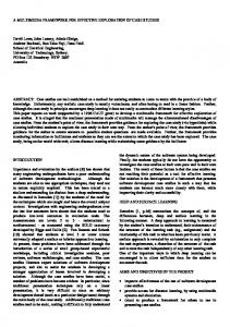
4. User Interface The graphical user interface of Smile! was built using the scripting language Tcl/Tk [5]. The primary motivation for this choice was to facilitate rapid prototyping and to make the GUI easy to modify and extend with new features. To make this possible, and to create reusable components for building general audio/video applications, Tcl/Tk was extended with new commands and widgets for audio and video. A snapshot of the graphical user interface of Smile! is given in Figure 1.
Figure 1 The Graphical User Interface of Smile!
5. Video Encodings Two different video codecs are available in Smile!: A JPEG codec and an experimental Wavelet codec.
5.1. JPEG Codec The JPEG codec is based on the ITU-T still image compression format JPEG (Joint Photographic Experts Group) [1]. In this encoding each frame of a video sequence is encoded independently of the other frames in the sequence as a JPEG still image. Thus only spatial redundancy is reduced by the codec and not temporal redundancy, as is the case with formats like MPEG and H.261. Consequently a JPEG codec requires more bandwidth than many formats that reduce redundancy also in the temporal dimension. However, there are a number of advantages making JPEG interesting for high quality videoconferencing applications, including • • • •
availability of low-cost high performance hardware codecs, low compression delay, potentially high image quality, image quality versus bandwidth tradeoff using the JPEG Q-factor.
There are several different compression schemes defined by the JPEG standard, including lossless JPEG and progressive JPEG. The algorithm used in Smile! is known as the baseline JPEG algorithm which is based on the block based discrete cosine transform, quantization and entropy coding. Image resolutions corresponding to fullsampled PAL or NTSC video signals. A 4:2:2 component subsampling is used, which means that the chrominance components of the YCrCb colorspace are subsampled by two horizontally. The JPEG images are fragmented into datagrams as specified by the RTP Payload for JPEG-compressed Video [4].
5.2. Wavelet Codec The experimental Wavelet codec uses the Wavelet transform in combination with quantization and entropy coding to compress the images of the video. The Wavelet transform gives a multiresolution representation of the images, which enables the receivers of the video stream to progressively reconstruct the original images with successively better quality. This hierarchical compression algorithm in combination with a layered multicast transmission architecture makes it possible to realize multipoint video conferencing sessions with multiple quality levels without needing to transcode the media. The fragmentation of the Wavelet-compressed video into datagrams is based on a proprietary RTP profile.
6. Audio Encodings Two different audio codecs are available in Smile!: A high quality 16-bit linear PCM codec and a low quality GSM codec. The sample rate for the PCM codec is configurable, but defaults to 16 kHz which is good enough for most situations. The bandwidth required for the 16 kHz PCM codec is 256 kbps, whereas the GSM codec consumes 13 kbps. In a multipart conference session each receiver must mix the incoming audio streams to a single stream that can be played back to the audio device. To make this possible the incoming audio streams are put in separate receiver buffers that periodically are mixed together to a playout buffer that is fed to the audio device. Since the signal levels of the audio sources can differ substantially, the amplitudes of the different sources can be scaled independently. Thus, the receiver of many audio sources can mix the incoming signals according to preference. In order to avoid wasting bandwidth unnecessarily, a silence suppression algorithm can be utilized to repress transmission of audio when a source is silent. A threshold value can be specified via the GUI, so that when the microphone level is below the threshold, the source is not transmitting the audio. A common problem with audio conferencing when not using headphones is echoing. The echoes occur when the received audio is played back through the speakers, recorded by the microphone and sent back to the originator. When the delay of the echo increases over a few milliseconds the effect is very annoying. To prevent echoes a net-mutes-mike function is implemented in Smile!. When net-mutes-mike is activated the microphone is muted whenever an audio packet with a signal energy above a certain threshold is received. This prevents audio played back through the speakers from being sent back to the originator, but also limits the interactivity of discussions slightly.
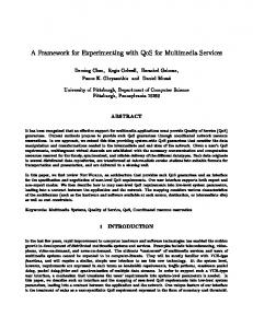
7. Session Management In addition to transmitting audio and video between a number of participants Smile! also maintains rudimentary session management information that identifies each participant by a canonical name and displays the status of each participating member of the conference. This information is periodically updated by RTCP packets. The main window of the Smile! GUI contains a participants list that identify all members of the conference session by an Internet-style canonical name in the form
[email protected]. The type of media each member is transmitted is illustrated by an icon. The participants list is depicted in Figure 2. Note also that for each member there is a checkbox for muting/unmuting the associated audio or video signal. Furthermore, for audio sources there is a volume slider for each member, making it possible control the volume of each source independently.
Figure 2 Participants list in Smile!
7.1. Session Initiation SIP, the Session Initiation Protocol, is a protocol for initiating and maintaining synchronous sessions over IP networks [7]. The proposed SIP standard is expected to be an important component of future IP telephony systems and other synchronous services like videoconferences. In order to study the features and possibilities with the protocol SIP signalling was implemented in Smile!. Using SIP signalling it is possible to invite members to a conference. A user can also specify actions that should be taken in response to an incoming SIP call. The priority feature of SIP was used to associate a number of different alerting methods with the priority levels. For instance, in a prototype demo system the priority "normal" was associated with an audible bell and the priority "urgent" was associated with a siren sound in combination with a blinking lamp on the wall. SIP also includes functionality for a redirection service. This was demonstrated in the prototype by having an incoming SIP call generate an SMS message sent to the callee's cellular phone. Figure 3 shows the user interface for SIP invitation that has been implemented in Smile!.
Figure 3 SIP Invitation GUI in Smile!
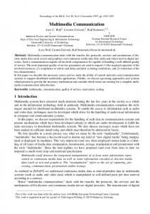
8. Streaming of Stored Media Clips Smile! can be used as a client to initiate streaming playback of media clips from a multimedia server. The media clips can be audio files or movies and can be streamed to all participants of a session. The intended use for this is to enable the participants of a synchronous collaboration session to jointly view a video clip or listen to an audio clip and to be able to discuss the media content in real time. The initiator of the media playback chooses the clip from a fileselection dialog (Figure 4) and can then interactively control the streaming of the media from a control panel (Figure 5).
Figure 4 Media Clip Selection Dialog
Figure 5 Streaming Media Control Panel The streaming of multimedia data is performed by a server called sserv. The currently supported file formats of media clips are RIFF audio files (Waveform files) and QuickTime movies. sserv transmits the media clips as RTP streams. The control interface between the client part integrated in Smile! and the sserv server is based on the Real-Time Streaming Protocol (RTSP) [8].
9. Remote Camera Control Interface A remote camera control interface is integrated into Smile!. A Sony EVID-31 camera or a Sony VID-P150 document camera, connected to the computer with a serial line can be controlled. A background daemon called rcamd is used to communicate pan, tilt and zoom commands to the camera. The remote Smile! application is connected to the rcamd daemon whenever the user enables the remote camera control. The camera is controlled by clicking the left mouse button while the mousepointer is in the video window corresponding to the camera
that is being remotely controlled. Holding the mouse button down and dragging the mouse pointer will move the camera in the desired direction. The speed of the movement is controlled by the distance the mousepointer is dragged from its original position. Zooming in and out is performed much in the same way using the middle mouse button instead of the left.
10. The rsmile Remote Control Interface A tool called rsmile can be used to control all aspects of Smile! from a remote machine. This can be useful in for instance the following two situations: • •
An expert user of Smile! can use the rsmile tool to control the behaviour of a remote instance of Smile! to assist an inexperienced remote user. Smile! might be running on a machine that doesn't have a display connected. In this case the rsmile tool can be used to control the application. The analogue video output port of the computer might be used for displaying the received video streams.
The graphical user interface of rsmile, depicted in Figure 6, looks very much like the GUI of Smile!. The GUI is just a graphical front end written in Tcl to the remote Smile! process. Whenever an action is performed in the rsmile GUI the corresponding Tcl commands are sent to the remote Smile! process for evaluation in Smile!'s Tcl interpreter. Instead of rendering the video of the transmitter window or the receiver windows a "proxy window" containing no video is displayed to the rsmile user. From these windows the video-related commands of the remote Smile! process are accessible. There is also a text widget available in the GUI of rsmile wherein any Tclscript can be typed in and sent to the remote Smile! process for evaluation. Using this feature it is possible to modify the behaviour and appearance of the remote Smile! application during execution.
Figure 6 The rsmile GUI
11. The WebSmile Video Gateway In an effort to extend the scope of multicast video conferences we have developed an RTP to HTTP gateway software, called WebSmile, that makes it possible for an Internet user to take part of multicast video streams, albeit at potentially high latency and low frame-rate, with the only prerequisite being access to the WWW
through a standard browser. WebSmile is a software component that is installed on an ordinary web-server that is connected to a multicast capable network. The software gives users access to multicast RTP video streams through the web-server using HTTP steaming. A conceptual model of the WebSmile architecture is given in Figure 7.
11.1. Client Side Two different techniques are used to enable the client browser to display the video that is streamed over HTTP; an experimental MIME-extension for displaying moving images and a Java applet. The MIME extension, known as multipart/x-mixed-replace, makes it possible to display sequences of JPEG or GIF images in an HTML page. Since it is not supported in all browsers this technique is complemented with a Java video player applet that is downloaded from the WebSmile server.
11.2. Server Side The WebSmile gateway is implemented as a server program executed on a web server through the common gateway interface (CGI). The program performs three separate functions depending on the parameters with which it is invoked: • • •
Monitor a multicast session and report back information about the video sources that are identified. Join a session and return an HTML-page with video displays. Start forwarding video over HTTP.
The first function is performed by joining the multicast address and port specified and listening to RTCP source description (SDES) advertisements. The members of the session are identified by a canonical name in the format
[email protected] and optionally by more verbose information like a real name, address, phone number etc. This information is reported back to the browser that originated the CGI-request as an HTML-form with a checkbutton associated with each identified session member. The user then indicates which video sources are to be monitored by checking the appropriate checkbuttons and posting the form back to the server. This invokes WebSmile in the second mode as described above to join the session and return the video display HTML page. This page contains a Java applet to display the video, in case the browser has been identified (through CGI environment variables) as non-capable of displaying multipart/x-mixed-replace content. The third mode of WebSmile is invoked when the references in the video HTML-page to the HTTP-streamed video are resolved. This is either an image hyperlink looking something like
(where 1234 is the source id of the video to be monitored) or an applet connecting explicitly to the web server with the same CGI parameters. In both cases the video streamed over HTTP conforms to the multipart MIME specification with a content type of image/jpeg for each multipart entity.
HTTP-requests WWWbrowser
WWW server
HTTP-responses HTML-pages HTTP video
RTP video RTCP
Common Gateway Interface
WebSmile
RTCP receiver reports RTCP source descriptions
Multicast network
Figure 7 Conceptual model of the WebSmile architecture
12. Mobile Videoconferencing In order to study how mobile users can benefit from videoconferencing capabilities the Smile! videoconferencing application has been ported to a handheld device with a wireless network. The Compaq iPAQ H3650 Pocket PC running the Linux operating system was selected as the target platform. The Compaq iPAQ comes with a 206 MHz Intel StrongARM processor, 32 Mb of memory and a 240x320 12 bit color display. It was also equipped with a IEEE 802.1 network interface, enabling its user to be fully mobile within the WaveLAN. In order to make the Smile! application usable on the limited display the graphical user interface was shrunk to fit the screen. This included scaling down all icons to a suitable size, changing the border sizes of widgets and changing the font size of all text labels and buttons. Furthermore, since video rendering space is scarce on the screen, a GUI option was added that enables the user to remove the menubar and window frame from a video window. Snapshots of the user interface are given in Figure 8.
Figure 8 Smile! on a handheld device with wireless network interface It is readily noted that the aspect ratio of a video window matches the iPAQ's display better if it is rotated 90 degrees into a "landscape" orientation. Therefore the X window system resize and rotate extension [13] was used, making it possible to change the orientation of the desktop. This is illustrated for a video window in Figure 9. Since the display depth is limited to 12 bits the video is converted from the 16 bit YCrCb representation that is the output from the JPEG or Wavelet codecs, directly into a 12 bit RGB representation with 4 bits for each component.
Figure 9 A video window of Smile! in portrait orientation The iPAQ is equipped with a 16 bit audio processor, a built-in speaker and microphone. Smile! can be used both to receive and transmit audio in either 16 bit linear PCM or GSM encoding. Since both the speaker and the microphone are built into the device, echo is very easily achieved. This can be avoided either by using the "netmutes-mike" feature or by using headphones that can be connected to the iPAQ. It is currently not possible to transmit video from the iPAQ.
13. Graphically Annotated Video In many situations the live video signals of a conference session are used not only to mediate the appearance of the participants, but also as a means of showing real objects, drawings, whiteboards or other scenes. A conference session can often be a discussion around something, a complex product prototype for instance, that is showed in a video window to all participants. In these situations it might be helpful to be able to annotate the video graphically to emphasize or indicate what is being discussed. For this reason Smile! has been extended with support for drawing graphical symbols onto a live video window. The symbols are transmitted to the receiving sites of the session as vector graphics objects and rendered on the corresponding video window, if the
user has enabled annotations. Thus, the graphical symbols are not changing the pixels of the actual video, which makes it possible to switch the annotations on and off. Currently, only two symbols are supported, an arrow symbol and a circle. To add an annotation to a video window, the desired symbols is selected from a menu and positioned using the mouse. The symbol can then be resized using the right mouse button. A live video window with annotations is shown in Figure 10.
Figure 10 Live video window with graphical annotations The graphical annotations are communicated between sender and receivers in application-specific RTCP APP packets. The RTCP APP packet header for all graphical annotations has the layout depicted in Figure 11. 0
8 flags
16 PT = 204
24
32
length SSRC
name = “gfxa” annotation id
type
annotation-specific data
Figure 11 RTCP APP packet header for graphical annotations The RTCP APP header contains a flags field of which the first two bits are the RTCP version, the following bit is a pad bit and the remaining five are unused for annotation packets. Then there is an eight-byte payload type identifying the RTCP packet as application specific (APP). The APP payload type is the decimal value 204. The length field gives the total length of the packet. The SSRC field (synchronizing source identifier) identifies the video stream that the annotation is associated with. The name field identifies the RTCP APP packet as a graphical annotation packet and should be assigned the string value "gfxa". The type field identifies the annotation type. Currently defined values are 1 for the pointer symbol, 2 for the circle symbol and 100 for the delete command that is used for removing annotations. The annotation id field is a unique identifier for a particular annotation. The rest of the packet contains variable length annotation-specific data. The annotation specific data format for the pointer and circle symbols are given in Figure 12. 0
8
16
x-coordinate orientation
0
24
32
y-coordinate size
8 x-coordinate
16
24
32
y-coordinate
radius
Figure 12 Annotation-specific data for pointer and circle symbols respectively
The RTCP APP annotation packets are transmitted whenever an annotation is created or changed. They are then retransmitted at every RTCP packet transmission interval to reassure that new participants joining the conference throughout the lifetime of the session are able to receive and display all annotations correctly. When an annotation changes, i.e. is moved, resized or rotated, a new RTCP packet is generated that identifies the annotation via the unique annotation id and contains the new parameters for the annotation. When an annotation is deleted a RTCP APP annotation packet of annotation type 100 and an annotation id identifying the annotation in question is transmitted. Delete packets have an empty annotation-specific part.
14. Stereoscopic Video An important characteristic of the human visual system is the ability to perceive depth resulting from the spatial disparity of the left and right eyes' viewpoints. Since most packet video transmission systems developed so far are limited to monoscopic imagery the perception of depth resulting from stereopsis is lost. Although there are other 3D depth cues such as obscuration, kinetic depth, relative size and lighting that can be conveyed by a 2D projection, true strereoscopic vision is only possible with stereopsis. In order to enable stereoscopic visual communication over packet networks two video sources (one for each eye's viewpoint) need to be transmitted and properly presented at the remote end using a 3D-visualisation system. Stereoscopic video has been implemented in Smile! to allow experimentation with 3D video communication over internetworks. The left and right viewpoint video channels should be carried as two distinct RTP streams so that individual demultiplexing and decoding is possible for systems that cannot display stereoscopic images. A transport protocol extension is needed to associate the two channels of a stereoscopic stream to each other and to identify which channel is the left and right viewpoint respectively. The RTCP protocol defines source description (SDES) packets for carrying information about associated RTP streams. SDES packets consist of a packet header followed by a number of source identification/description pairs. The source identification is a 32-bit synchronising source identifier (SSRC) that uniquely identifies an RTP stream. Each RTP stream carries the SSRC identifier in its RTP header. The source description is a list of SDES items. An SDES item is a variable length entity consisting of an 8-bit item type identifier, an 8-bit length field and a variable length source identification string. Currently defined SDES item types include CNAME, NAME, PHONE, EMAIL, LOC, TOOL, NOTE, APP and PRIV. Each SDES item describes an RTP stream by some attribute like a real name or a phone number. The private extension (PRIV) SDES item is intended for experimental or applications-specific SDES extensions. In addition to the 16-bit SDES item header the PRIV item also includes an 8-bit prefix length field and a variable length prefix string containing an ASCII identification of the PRIV item subtype. Since PRIV items of unrecognised subtypes are required to be silently ignored, new source description items can be introduced without requiring packet type value registration. If wider use is justified after testing it is recommended that the PRIV item is redefined as a unique SDES item, without the prefix identification, and given an item type that is registered by the Internet Assigned Numbers Authority (IANA) [15]. Thus, SDES PRIV items are ideal as containers for information associating the channels of a stereo pair. The format of the stereo SDES PRIV item that has been used in Smile! is shown in Figure 13. 0
8 SDES ID=8
16 length
32
24 prefix length
prefix string
“3D-video” SSRC of ... ... other channel’s RTP stream
channel id
Figure 13 RTCP SDES PRIV item for stereoscopic video: SDES ID (8 bits), length (8 bits), prefix length (8 bits), prefix string (64 bits), SSRC (32 bits), channel id (8 bits) The prefix string field is an 8 octets wide ASCII string that identifies the PRIV packet as a stereoscopic video source description item. The string value "3D-video" is used for stereo PRIV items. The prefix length should consequently be set to 8. The SSRC field contains the 32-bit numeric synchronising source identifier of the other channel's RTP stream. (That is, for a stereo PRIV item identifying a left-eyed RTP stream this field contains the
SSRC of the corresponding right-eyed RTP stream and vice versa.) The channel id identifies the RTP video stream as being the left (channel id 1) or right (channel id 2) viewpoint of a stereo video pair. The stereo SDES PRIV item should be included in the SDES item list of the RTCP packets periodically transmitted to the destination address of the associated RTP video stream. This assures that late joining members (in case of a multicast session) can identify the source as a stereo video channel. Note that it is sufficient with only one of the RTP video streams of a stereo pair being identified as stereoscopic with SDES PRIV items, since it gives a complete association of the two streams. However, since RTCP packets are implicitly associated with an RTP stream by UDP port number (the port number of the RTCP stream being one higher than that of the RTP stream) it might be desirable to mutually identify the stereo pair by both RTCP streams. This is useful if the reception of a stereo stream is subdivided in separate processes for each channel, or indeed is distributed on two hosts. The operation if the stereo SDES PRIV packet streams are inconsistent is undefined. The transmitting side of the system uses two identical cameras, arranged with parallel axes and an inter-axial separation of about 65 mm. To enable stereoscopic transmission the user selects whether the video is the left or right viewpoint by checking the corresponding checkbox in a pulldown menu. A snapshot of the graphical user interface is shown in Figure 14.
Figure 14 User interface for viewpoint selection Once a viewpoint is selected from the graphical user interface, the application starts transmitting RTCP SDES PRIV packets for the stereoscopic extension. In order to do this, the application must know the synchronising source identifier (SSRC) of the other viewpoint's RTP stream. In this protoype implementation the SSRC identifiers of the RTP streams were user-configurable by command line parameters. Allocating SSRC identifiers in this way isn't recommended, since it compromises identifier uniqueness, but was nevertheless chosen for simplicity. A better approach would be to generate the SSRC identifiers randomly, as exemplified in Appendix A6 of the RTP specification [2], and to use some application-specific set-up protocol to exchange the identifiers between the sending peers. On the receiving side stereoscopic video streams are identified when the RTCP source description packets including the stereoscopic video extension items arrive. The list of contributing participants in Smile! (see Figure 2) is updated with an icon representing a stereoscopic video stream, whenever two video streams are identified as left and right viewpoint of a stereoscopic video pair respectively. Time-multiplexed stereoscopic video is displayed in a window or full-screen using Open GL's quad-buffer rendering and is viewed using CrystalEyes shutter glasses from StereoGraphics [14]. A checkbutton for switching between stereoscopic and monoscopic rendering is available from a pull-down menu. The horizontal image translation needed to converge the views is controlled by the left and right arrow-keys on the keyboard. Thus, the convergence plane can be interactively adjusted to different perceived depths, depending on viewing conditions and user preference.
15. Summary and Conclusions This paper has presented a framework of real-time multimedia collaboration tools. The properties of the audio/video collaboration tool Smile! was discussed and its interoperation with other applications was described. The communication architecture that is being used by the application framework is based on IP and RTP.
Scalability aspects of broadband multimedia collaboration include efficient distribution of auidio/video packets using IP multicast. For deployment in heterogeneous environments a layered multicast approach might be appropriate. In situations where lack of multicast routing and presence of firewall prevents multimedia conferencing in its basic form an RTP to HTTP video gateway like WebSmile may be of use. Furthermore, the interoperation of a videoconferencing system with a multimedia streaming server was discussed in this paper, and the coupling between Smile! and sserv was given as an example. Mobility can be achieved for multimedia collaboration tools by implementation on handheld wireless devices. This was exemplified with the Smile! implementation on the Compaq iPAQ handheld computer. A combination of graphical annotations and live video can be a powerful tool for collaboration. The design and implementation of a graphical annotation tool built into Smile! was described in this paper. Another interesting enhancement of traditional videoconferencing is to enable stereoscopic video streams to be transmitted and displayed. This makes it possible to perceive depth in the video delivered by a communication system, enhancing realism and enabling new types of applications. To conclude, a rich toolkit of multimedia collaboration software can substantially increase the quality of distributed collaborative work. One such framework of applications, built around the Smile! teleconferencing tool, was presented in this paper.
References [1] ITU-T Recommendation T.81, ”Information technology – Digital Compression and Coding of ContinuousTone Still Images – Requirements and Guidelines”, September 1992. [2] Schulzrinne, Casner, Frederick, Jacobson, ”RTP: A Transport Protocol for Real-Time Applications”, RFC 1889, January 1996. [3] Berc, Fenner, Frederick, McCanne, ”RTP Payload for JPEG-compressed Video”, RFC 2035, October 1996. [4] Schulzrinne, ”RTP Profile for Audio and Video Conferences with Minimal Control”, RFC 1890, January 1996. [5] Ousterhout, ”Tcl and the Tk Toolkit”, Addison-Wesley, 1994. [6] Deering, ”Multicast Routing in a Datagram Internetwork”, PhD Thesis, Stanford University, December 1991. [7] Handley, Schulzrinne, Schooler, Rosenberg, "SIP: Session Initiation Protocol", RFC2543, March 1999. [8] Schulzrinne, Rao, Lanphier, "Real Time Streaming Protocol", RFC 2326, April 1998. [9] Watson, Sasse, "Evaluating audio and video quality in low-cost multimedia conferencing systems", Interacting with Computers, no. 8 1996, pp. 255-275. [10] Bruce, "The role of the face in communication: Implications for videophone design", Interacting with Computers, no. 8 1996, pp. 166-176. [11] Kies, Kelso, Williges, "The use of scenarios to evaluate the effects of group configuration and task on video-teleconferencing communication effectiveness", Third Annual Mid-Atlantic Human Factors Conference, Blacksburg, VA, March 26-28 1995. [12] Parnes, ”The mStar Environment - Scalable Distributed Teamwork using IP Multicast”, September 1997. [13] Gettys, Packard, "The X Resize and Rotate Extension Protocol - RandR", November 8, 2000. [14] [20] L. Lipton, "CrystalEyes handbook", StereoGraphics Corporation, 1991. [15] [24] Internet Assigned Numbers Authority, http://www.iana.org/