Snapshot Spectral Imaging using Optimized Diffractive Optical Elements Martin De Biasioa , Thomas Arnolda , Andreas Tortschanoffa , Andreas Hermerschmidtb , and Raimund Leitnera a CTR
Carinthian Tech Research AG, Europastrasse 4/1 St. Magdalen, 9524 Villach, Austria Photonics AG,Albert-Einstein-Str. 14,12489 Berlin-Adlershof, Germany
b HOLOEYE
ABSTRACT We present a CTIS system that uses an optimized diffractive optical element (DOE) to project the spectral and spatial information simultaneously onto a CCD. We compare the DOE with and older approach based on glass gratings and found that the DOE gave an improved spectral response. We argue that a DOE is the most effective approach for CTIS. Keywords: snapshot, CTIS, DOE, optimization
1. INTRODUCTION A computed tomography imaging spectrometer (CTIS) captures both spatial and spectral information simultaneously.2 A CTIS consists of 3 optical elements: two imaging lenses separated by a diffractive optical element (DOE). This paper is concerned with the DOE. The purpose of the DOE is to disperse a hyper-spectral data cube onto a CCD. In a previous paper1 we presented a snapshot demonstrator that used a pair of, off the shelf, glass line gratings. These have the disadvantage that they are optimized for a single wavelength and their transmission performance deteriorates over the required spectral range. Here we present the optimization of a diffractive optical element (DOE) that overcomes the problem of the standard glass grating. We measured the overall performance of the standard glass gratings and the optimized DOE and compared the two approaches in terms of transmission efficiency.
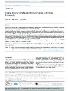
λ y x
Figure 1. Geometric relationship between the hyper-spectral data cube and the dispersion pattern on the matrix detector. The center image is the zero order sub-image, the surrounding sub-images are referred to as first order sub-images.
The optical setup of our CTIS system is shown in Fig. 2. By imaging the scene through a diffractive optical element CTIS captures both spatial and spectral information of an object. The geometric relationship between Further author information: (Send correspondence to Martin De Biasio E-mail:
[email protected], Telephone: 0043 4242 56300 224)
the hyper-spectral data cube and the dispersion pattern is shown in Fig. 1. The dispersion matrix consists of the un-dispersed zero order sub-image in the center, surrounded by the first order sub-images. For further analysis of the acquired data, the spatial and spectral information of the hyper-spectral data cube have to be reconstructed.3, 4
CCD camera DOE
Field Stop
Re-imaging Lens Collimating Lens
Front Lens Image plane Figure 2. Optical setup for a computed tomography imaging spectrometer. A diffractive optical element (DOE) disperses both spatial and spectral information of an object. Custom optics image the dispersed data onto a CCD detector.
In this paper we test whether the new grating has a better spectral response than the line gratings. We compared the intensity distribution in the zero and first order sub-images over the desired wavelength range in 10nm steps using a tunable filter. We found that the new grating gave a better frequency response, especially at short wavelengths, than the line grating used in our first demonstrator.
2. OPTIMIZING THE DOE Our first snapshot demonstrator used a pair of, off the shelf, line gratings. We sandwiched two line gratings together, to disperse the image in two dimensions. However, these gratings are optimized for a single wavelength and their transmission performance deteriorates over the specified spectral range (400nm to 800nm). As a result the intensity in the zero order sub-image is close to zero, yet the diagonal first order sub-images are saturated. We decided to optimize the DOE to increase the transmission efficiency over the wavelength range. We used binary transmissive DOEs made from fused silica. These operate as linear 1:3 beam splitters. To create a 3x3 dispersion matrix we used two linear 1:3 beam splitters in crossed arrangement. The ratio of intensity between the zero order and the first order sub-images varies with wavelength. In scalar approximation, the wavelength-dependent phase modulation of a binary grating of depth d and refractive index n(λ) is given by Φ=
2π d(n(λ) − 1) λ
(1)
The goal of the optimized DOE was to equally split the intensity ratios between the zero order sub images and first order sub images at an acceptable level over the entire wavelength range λmin (400nm) ... λmax (800nm). The design was carried out for a center wavelength λC which, neglecting material dispersion, can be approximated as
λC =
2λmin λmax λmin + λmax
(2)
The final design wavelength was determined numerically taking the material dispersion into account. The optimization was done with the aim that the intensity ratio r=η0 : η1 for the intensity in the zero order subimage and the first order sub-image should be identical at λmin and λmax , and inverted at the center wavelength λC , so that η0 λmax η1 λ C η0 λmin = = . η1 λmin η1 λmax η0 λ C
(3)
For the desired diffraction angles, the grating period of the beam-splitter was chosen as 12.45µm and the elements were fabricated using an electron beam writer (Leica ZBA 23H) to create the desired pattern in e-beam resist. A wet tech process transferred this structure to the Chromium layer underneath the resist. A final reactive ion etching process with a target depth of 574nm using a plasma etcher (Oxford Instruments Plasmalab 80+ICP 65) was used to create a micro relief surface in the fused silica substrate. The actual depth obtained was 12 nm (equivalent to 2%) too shallow. As a result the zero order sub-image was stronger than intended at long wavelengths. The power ratio for the ideal depth was expected at 3.75:1 at 400nm and 800nm. The inverse power ratio was expected 3.2 at the center wavelength λC . In the curves shown in Fig. 3, we simulate the diffraction efficiencies and power ratios for a single linear 1:3 grating. The performance of the 3x3 array generator is then obtained in good approximation by squaring the given values.
Figure 3. Simulation result for the power ratio between the zero order and first order and the corresponding diffraction efficiencies for ideal depth (top) and the actual depth (bottom).
3. MEASUREMENT SETUP In our experiments we will compare the transmission efficiency of a standard glass grating with our DOE as a function of wavelength. The measurement setup is shown in Fig. 4. An Axio Imager A1m (Carl Zeiss, Germany) fluorescence microscope, was used to acquire a snapshot data sets for the comparison of a standard glass grating and the optimized custom design DOE. The CTIS system was attached to the side port of the fluorescence microscope. The measurement samples were excitated with a halogen lamp. A 10 bit 1/2.5 inch color CCD camera (mvBlueFox, Matrix Vision, Germany) with a resolution of 2592x1944 TM pixels. A liquid crystal tuneable filter (LCTF) (Varispec , CRi, MA, USA) was used to vary the measured wavelength from 400 to 720nm in 10nm steps with a FWHM of 7nm.
CCD Camera
LCTF Axio Imager A1m
CTIS optics
Figure 4. Measurement setup for the CTIS system. The CTIS was attached to the side port of a Axio Imager A1m fluorescence microscope (Carl Zeiss). The LCTF in the optical path is only used for calibration.
4. RESULTS We compared the optimized DOE with the standard glass grating used in our first demonstrator. Using an LCTF we acquired a white standard in 10nm steps and compared the power ratio between the zero order sub-images and first order sub-images. To avoid any variations caused by the lenses or camera, only the dispersive optical element was changed between the acquisitions.
4.1 Visual comparison of the standard glass grating and the DOE The improved spectral response of our system can be illustrated by comparing images formed by the glass grating with those produced by the DOE, see Fig. 5. The Fig. shows dispersed images of a USAF calibration pattern at 450nm, 550nm and 600nm. The top row shows results from the standard glass grating; the bottom row results from the DOE. With the glass grating the light intensity is unevenly distributed between the zero order sub-images and the first order sub-images. Although the diagonal first order sub-images are well lit the light intensity in the zero order sub-image and the horizontal and vertical first order sub-images are close to zero. The distribution of the intensity improves at longer wavelengths although the intensity in the zero order subimages and the horizontal and vertical first order sub-images is still lower than in the diagonal first order sub-images. Compared to the results of the glass grating, the optimized DOE disperses the intensity more homogenously to the zero order and first order sub-images, see Fig. 5. The bottom row in Fig. 5 illustrates that at short wavelengths the light intensity within the zero order and first order sub-images is nearly equal and stays this way over the whole wavelength range.
Standard glass grating Optimized DOE 450nm
550nm
600nm
Figure 5. Standard glass grating vs. optimized DOE. The optimized DOE disperses the intensity equally to the zero and first order sub-images.
4.2 Numerical comparison of the standard glass grating and the DOE For verification we defined a region of interest (ROI) of 20x20 pixels within the zero order and first order subimage and calculated the mean intensity within the ROI. To compare the two gratings with the simulations of the optimized DOE we calculated the power ratio between the zero order and first order. The plots in Fig. 6 show the result for the standard glass grating and our custom design DOE.
4.3 Standard glass grating As the standard glass grating is optimized for a center wavelength of 632nm the power ratio at this wavelength is approximately 0.5 between the zero order sub-images and the horizontal and vertical first order sub-images. Ideally the ratio should be equal to 1 as the intensity distribution between the the zero order sub-images and first order sub-images should be equal. This ratio gets worse for the power ratio between the zero order sub-images and the diagonal first order sub-images, as twice the amount of light light is dispersed to the first diagonal order. This results in a poor power ratio for short wavelengths.
Figure 6. Zero to first order power ratio comparison between a standard glass grating and our custom design diffractive optical element. The plot shows the ratio between the zero order and first order in the diagonal (n0/n1d) and the ratio between the zero order and vertical first order.
Standard glass gr Optimized DOE
4.4 Optimized DOE
Compared to the standard glass grating our custom design DOE shows performs better over the specified wavelength range. Especially at short wavelengths the power ratio between the zero order sub-images and all the first order sub-images measured data600nm is shown in Fig. 6 (right). Moreover, the measured data and the 450nm is even. The 550nm simulated data are well correlated, see Fig. 7.
Figure 7. Simulated DOE power ration vs. measured DOE power ratio.
5. CONCLUSIONS The work presented here describes the optical optimization of a DOE for a CTIS snapshot imaging system. The DOE was optimized for transmission efficiency for the zero order and first order sub-images in the wavelength range from 400nm to 800nm. We compared the measurement results of our first prototype that used two crossed glass gratings1 with our current prototype using the custom design DOE. We conclude that the new CTIS system gives a higher performance than our first prototype.
6. ACKNOWLEDGEMENT The work described in this publication was funded by the bridge project 820116 of the Austrian Funding Agency FFG. The industrial partners in this project were: IPAC Improve Process Analytics and Control GmbH, Villach, Austria; Tissue Gnostics GmbH, Vienna Austria; and the University of Klagenfurt, Austria.
REFERENCES [1] M. De Biasio, T. Arnold, A. Tortschanoff, and R. Leitner. Snapshot Spectral Imaging Demonstrator. Proceedings SPIE, 8032:803212–803212–6, 2011. [2] Bridget K. Ford, Michael R. Descour, and Ronald M. Lynch. Large-image-format computed tomography imaging spectrometer for fluorescence microscopy. Optical Society of America - OPTICS EXPRESS, 9(9):444– 453, October 2001. [3] William R. Johnson, Daniel W. Wilson, Wolfgang Fink, Mark Humayun, and Greg Bearman. Snapshot hyperspectral imaging in ophthalmology. Journal for Biomedical Optics, 12(1):014036–1/014036–7, January/February 2007. [4] Michael D. Vose and Mitchel D. Horton. A heuristic technique for ctis image reconstruction. Optical Society of America - Applied Optics, 46(26):6498–6503, September 2007.