Dip. di Elettronica, Politecnico di Torino, Italy, Email: {last name}@tlc.polito.it ... proper response to SNMP request for the different types of MIB variables are described. .... messages allow the agent to automatically notify the SNMP manager of ...
SNMP Management in a Distributed Software Router Architecture Andrea Bianco, Robert Birke, Fikru Getachew Debele, Luca Giraudo
Dip. di Elettronica, Politecnico di Torino, Italy, Email: {last name}@tlc.polito.it Abstract—Multi-stage software router architectures permit to overcome several limitations of single-stage software routers, allowing to expand the number of available interfaces and to increase the overall throughput. However, a multi-stage software router, despite being composed by several internal elements, must externally appear as a single device. A control protocol called DIST was defined to solve this problem from the control plane point of view for a previously proposed multi-stage architecture. In this paper, we tackle the same problem from the network management point of view. We define a management architecture and a manager-agent communication model to coordinate the information residing on the single elements of the multi-stage router to present a unified view to the external network management station issuing SNMP requests. We analyze the different variable types contained in the SNMP MIB and divide them into different categories depending on how the response to a SNMP request is compiled. The handling methods used to create the proper response to SNMP request for the different types of MIB variables are described. Analytical computations shows that the proposed management architectures does not affect the multistage software router scalability.
I. I NTRODUCTION Networking equipments, and routers in particular, are characterized by the development of proprietary architectures. This situation yields to high cost in terms of both equipment and training, because network administrators need to manage different vendor devices or they are forced to a single vendor scenario. This situation drove network researchers to identify software routers (SRs) as an appealing alternative to proprietary devices. SRs are based on off-the-shelf personal computers (PCs) running open-source network application software like Linux, Click modular router or XORP [1]–[3]. The main benefits of SRs include: wide availability of multivendor hardware and documentation on their architecture and operation, low cost and continuous evolution driven by the PC market’s economy of scale. Furthermore, open source SRs provide the opportunity to easily modify the router operation, resulting in flexible and configurable routers. Proprietary network devices often lack programmability and flexibility. Criticisms to SRs are focused on limited performance, software instability, lack of system support, scalability issues, and lack of functionalities. Performance limitations can be compensated by the natural evolution of the performance of the PC architecture. Current PC-based routers and switches can sustain traffic load in the range 1-5 Gbit/s [4], [5], which is enough for a large number of applications. However, high-end performance and large size devices cannot be easily obtained on a single PC.
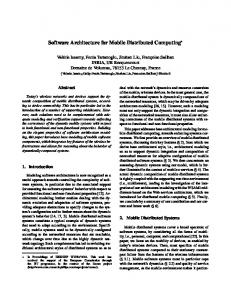
Fig. 1.
Multi-stage Software Router Architecture
To overcome these limitations, a multi-stage architecture has been suggested in [6]. The multi-stage architecture exploits classical PCs as elementary switching elements to build large high-performance routers. The proposed architecture (shown in Fig. 1) has three stages: the layer 2 front-end load balancers (LBs), acting as interfaces to the external networks, the layer 3 back-end routers providing the IP routing functionality and an interconnection network to connect the two stages. In the current implementation, the interconnection network is simply an Ethernet switch, the load balancers can be either hardware or software based, and the back-end routers are PCs running the Linux IP stack. The multi-stage architecture comprises a control entity, named virtual Control Processor (CP), that manages, controls and configures the whole architecture. The virtual CP hides the internal details of the multi-stage architecture to external network devices and runs on a selected back-end router. The key advantages of such architecture are the ability to: •
•
• •
•
overcome the performance limitation of single PC-based routers by offering multiple, parallel forwarding paths; upgrade router performance by incrementally adding/upgrading internal elements; scale the number of interfaces; recover from faults providing resilience through automatic reconfiguration of the internal elements; provide functional distribution to overcome single-PC CPU limitations by offloading CPU-intensive tasks.
However, these advantages come at the cost of control and management complexity. This complexity problem has partially been addressed from the control plane perspective [7]: An internal control protocol named DIST has been developed to: i) configure the architecture; ii) coordinate the routing process among back-end routers and the load balancing function among LBs; and iii) provide automatic fault recovery mechanisms. Furthermore, DIST dynamically maps the virtual CP on one of the back-end routers. In this paper we tackle the management plane issue (Sec. II) in the considered multi-stage architecture. A SNMP dualrole entity, named aggregator (Sec. III), is introduced to create a multi-stage architecture management base information (Sec. V- VI). Sec. IV describes the required communication model in the proposed architecture, meanwhile Sec. VII reports a scalability analysis. Finally, the paper is concluded in Sec. VIII. II. P ROBLEM D ESCRIPTION Networks require management procedures to be successfully operated. To reach this goal, network devices keep track of management information, such as cross-traffic, interface status and general system statistics. This information is organized into a management information base (MIB) [8] accessible through different management protocols such as SNMP, NetConf and NetFlow. We focus on SNMP [9], the most widely used protocol [10]. SNMP is based on a manager-agent model consisting of an SNMP manager, an SNMP agent and a managed device deploying a MIB. The SNMP manager provides the human interface to the management system, while the SNMP agent interfaces the manager and the device MIB. Managers and agents use SNMP messages for information exchange. SNMP messages comprise request, response and trap messages. Requests can be either get or set a specific MIB variable. The agent, upon a request reception, sends back a response message with the result of the operation. Trap messages allow the agent to automatically notify the SNMP manager of important events. Whereas in a single device MIB variables are directly accessible, in a multi-stage architecture the MIB information is distributed among different internal elements requesting additional complexity to compile the response. Indeed, request processing might require several steps to collect and, if necessary, to aggregate the information residing on different internal elements. The management of the multi-stage router requires to provide a single-entity view to external devices. Therefore, it is necessary to address the problem of mapping and combining the distributed information into an aggregated view. This problem is twofold: i) definition of a communication model to collect the distributed data and ii) mapping the various data to create a single-entity view. The agent residing in the multistage software router must coordinate the internal elements and operate on the MIB information distributed among the internal elements to create such a single-entity view.
Fig. 2. Management System Used in Multi-Stage Software Router: logical architecture.
III. P ROPOSED M ANAGEMENT A RCHITECTURE Three basic approaches for network management systems (NMS) exist: centralized, hierarchical and distributed [11]. The centralized approach uses a single management entity to collect the information and control the entire network. The hierarchical architecture uses the concept of manager of managers sitting at a higher level and requesting information from smaller domain managers in a tree like fashion, while the distributed approach uses a peer-to-peer architecture where multiple domain managers communicate with each other. Our proposed SNMP management system for the multistage router uses the hierarchical architecture approach. One SNMP dual-role entity, named aggregator, coordinates the internal, independently running, SNMP agents, and interacts with the external managers issuing SNMP requests. The aggregator is logically one of the modules of the virtual CP, the entity in charge of architecture control and coordination. However, it may run independently of other modules, possibly in a different back-end router. Load balancers redirect any external SNMP requests to the aggregator. When a SNMP request is received, the aggregator queries the internal SNMP agents to obtain the required MIB information and aggregates the information representing the whole multi-stage architecture. In other words, the aggregator is a dual-role entity located at the mid-level of the hierarchy: for external managers it acts as an agent and for internal agents it acts as a manager. Fig. 2 depicts this logical architecture. In terms of real implementation, whereas LBs and the switch (may) run an SNMP agent, back-end routers host both the aggregator and the agent functionalities. More precisely, each back-end router runs two instances of an SNMP process: an aggregator (listening on the standard SNMP port to be reachable from external hosts) and a standard agent listening on a different (configurable) port, used for internal communication only. Even if all the back-end routers are listening on the standard SNMP port, only one aggregator handles the external requests, because LBs forward SNMP request to the active aggregator only which resides on the back-end router designated as the one hosting the virtual CP by the DIST protocol. The standard SNMP agent instance permits to have the same interface towards all elements of the architecture and is used to collect the local information.
All back-end routers run both SNMP instances for resilience purpose. Indeed, if the currently active aggregator fails, another one can quickly take over, avoiding management failures. The take over procedure is taken care by the DIST protocol. When DIST detects a failure of the current aggregator, it elects a new one and reconfigures the LBs to properly redirect SNMP traffic. Observe that not all the internal elements may be SNMPcapable. Whereas back-end routers can be assumed to be SNMP-capable because they are based on Linux PCs, LBs, especially if hardware based, might not run an SNMP agent. Therefore, we assume two classes of load balancers: SNMPcapable and SNMP-incapable. This assumption affects the way in which the aggregator collects and computes MIB variables. In the first case, the aggregator can directly collect the proper information from the LBs agents. In the second case, either some MIB variables are approximated on the basis of the data available at the back-end routers or an alternative collection mechanism is deployed, as detailed in Sec. VI. To ease information sharing among aggregators (which is needed for a quick takeover in case of failure) and communication with the DIST protocol entity, the architecture also comprises a database. Among others, the database stores configuration information of the internal elements and most MIB counters. If the LB is not SNMP-capable, a minimal set of interface statistics, namely the received/transmitted bytes/packets and the link speed information are also saved in the database. Database resilience issues are not discussed because standard techniques can be adopted. The management architecture proposed in this paper was implemented and verified in a test-bed, shown in Fig. 1. More precisely, the prototype is based on a customized version of Net-SNMP [12] (ver. 5.4.2.1) and MySQL DBMS in addition to the software required to implement the multi-stage architecture. The proposed aggregator module shares some features with the SNMP proxy agent, documented in RFC 2576 [13]. However the purpose of a proxy agent is message translation between the different SNMP versions, while the work presented here focuses on creating a single-entity view of the multi-stage architecture to be presented to external SNMPcapable peers. IV. M ANAGER - AGENT COMMUNICATION
MODEL
The standard communication scenario used in SNMP [14] works for a single device which has all the information in the local MIB. However, in the studied multi-stage architecture, as already stated, the aggregator does not have the whole information locally available. This requires a modification to the standard SNMP manager-agent communication model. Fig. 3 shows the modified manager-agent communication model. The steps highlighted in the dashed box are the required extension to deal with the multi-stage architecture. Upon a request reception, the aggregator agent decodes the request to extract the object identifiers (OIDs) and checks the variable availability. If the variable is locally available, the
Command Responder/ Commander
Dispatcher Receive SNMP Request from Network prepareDataElement
Message Processing Model
Security Model
processIncomingMsg
Process PDU createInternalPDU
prepareOutgoingMsg
generateRequestMsg
Send SNMP Request to Internal Agents Receive SNMP Response from Internal Agents prepareDataElement
processIncomingMsg
aggregateResponsePDU returnResponsePDU
prepareResponseMsg
generateResponseMsg
Send SNMP Response to Network
Fig. 3. Modified incoming request scenario diagram for the multi-stage software router
aggregator manager responds reporting the current variable value. Otherwise, the aggregator sends SNMP requests to the appropriate internal element(s), collects the response(s) received within a given timeout 1 and, if required, aggregates the data to create the single-entity MIB variable. Finally, the aggregator agent answers to the original external SNMP request. If multiple responses are expected from the internal elements, a response to the external manager’s request is sent on the basis of the available information at a given time, even if some responses from internal agents are not available yet. For those elements which did not respond for whatever reason, the aggregator uses, if available, the corresponding variable value saved in the database at the previous successful request. On reception of a new request for a counter type MIB variable, if the agent comes back to service, the aggregator checks to detect any variable re-initialization: if found, the old value contained in the database and the newly available counter value are summed up to mask the discontinuity. This compensation guarantees that counters are kept monotonically increasing. Violating the monotonicity behavior of counters would be disturbing for the external management software, because these values are typically used to compute temporal trends. V. M ULTI - STAGE ROUTER MIB In the MIB definition of our multi-stage software router architecture, we mainly consider, among all variables defined 1 In
our implementation, the internal timeout was to one second
in the MIB tree, the system, the interface (IF) and the IP group objects. The MIB variables can be grouped into two main categories, based on how the aggregator computes the response: a) Global Variables: This category contains variables which are global for the multi-stage software router, e.g., the routing table (ipRouteTable), the system up time (sysUpTime) or the system name (sysName). These variables do not depend on a specific internal element; hence, they are stored in the database to ease information sharing among all aggregators. A response to an external SNMP request for this type of variables translates simply into a query to the database. The database might be populated by the aggregator itself or by the DIST daemon depending on the specific information. For example, the system name is provided by the aggregator, while the routing information is updated by DIST. b) Collected Variables: This category comprises all the variables requiring collection of data from one or more internal agents, e.g., interface information. A further division is between specific and aggregated variables. Specific variables can be fetched through a single request to a specific internal element. This group comprises all the variables containing specific properties of an internal element, e.g., the link status (ifOperStatus) or the link speed (ifSpeed). Instead, aggregate variables need multiple queries to different internal agents and require some kind of data aggregation. For instance, the total number of received packets at the IP layer (ipInReceives) or the discarded packets at the interface (ifInDiscards) are computed using counters from several internal elements. VI. S INGLE - ENTITY MANAGEMENT INFORMATION
VIEW
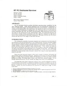
Global and collected variables are easy to handle: a simple request forwarding either to the database manager or to an internal agent is needed. Thus, we focus on how to compute the more complex aggregate variables. These variables mainly comprise IF and IP counters. Fig. 4 shows the main counters involved during packet forwarding, both in a single device router and in the multistage software router. The challenge is to define a mapping between the counters on the left, representing the singleentity view we want to achieve, and the counters on the right distributed over the three stages of the multi-stage architecture. In the following subsections we present such mapping. Where ambiguity might exist, we use an over-line to indicate the mapped computed variables and the superscript LB and BR for counters at LB or back-end router interface respectively. Furthermore, for simplicity, we define if InP kts as the sum of both unicast (if InU castP kts) and non-unicast (if InN U castP kts) packets. A. if InOctets, if InErrors and if InU nknownP rotos if InOctets, if InErrors and if InU nknownP rotos count respectively the number of received bytes, the number of discarded packets due to errors and to unknown/unsupported protocols. These counters are interface specific and, therefore, simply treated as collected variables.
As introduced in Sec. III, the computation of MIB variables may be difficult because some elements may be non SNMPcapable. For this reason, we consider three different cases: • SNMP-capable LBs: SNMP messages are used; • SNMP-incapable, DIST-capable LBs: The existing control plane is extended to transport minimal traffic statistics (e.g. packet and byte counters); • SNMP-incapable and DIST-incapable LBs: Data collection is not possible. Counters are approximated using the information available at the back-end routers (which are SNMP-capable), assuming a uniform distribution of traffic among front-end interfaces. Unfortunately, if InErrors and if InU nknownP rotos variables are not available in this case, because these events occur at LBs’ interfaces only. Similar considerations apply to the outgoing counterparts: if OutOctets, if OutErrors and if OutU nknownP rotos. B. if InDiscards As defined in the RFC 1213 [8], the variable if InDiscards counts the packets which, even if correct at reception time, are discarded by the device for any reason. We use this definition to compute all packets lost while traversing the internal network of the multi-stage architecture. However, it is not possible to track the exact path (and thereof the exact counters involved) of each packet within the multistage architecture, due to the unpredictable decision of the load balancing scheduler. Hence, we define Di as the share of packets internally discarded for interface i. Di is computed as the difference of the correctly received packets at the input interface of the LB (if InP ktsLB i ) and the sum of correctly received packets at all the interfaces of the back-end routers RBR , weighted by wi , the percentage of traffic received at interface i. RBR and wi are computed as: R
BR
=
M X
(if InP ktsBR j )
(1)
if InOctetsLB i PN LB if InOctets k=1 k
(2)
= if InP ktsLB − wi RBR i
(3)
j=1
wi
=
where M is the total number of back-end router interfaces, and N the total number of external LBs interfaces. Thus, Di if InDiscardsi
=
if InDiscardsLB i
+ Di
(4)
The above formulas make the implicit assumption that the loss probability is the same on all internal paths, but it has the nice property of being completely independent of the internal load balancing scheme adopted. Thanks to this property, the same procedure can also be applied on the reverse path to compute if OutDiscardi without knowing the result of the routing operation. In case of SNMP-incapable and DIST-incapable LB, if InDiscardsi is directly approximated by Di , replacing if InOctets and if InP kts in Eq. (1)-(4) with the received
'
! " ! "
#
#
)
#% #$
! " ! "
#'
#
#% #$
!
'
(
&
'
(
!
&
&
*
#
(
*
#
(
Fig. 4. Main IF and IP counters involved in packet forwarding for a single-stage router (right) and the multi-stage software router (left). For simplicity, if InP kts represents both if InU castP kts and if InN U castP kts.
bytes rxBytes and received packets rxP kts statistics stored in the database by DIST.
VII. S CALABILITY A NALYSIS
C. if InP kts if InP kts is the sum of all the corresponding counters at the back-end routers weighted by wi . if InP ktsLB i
is re-initialized only if all the back-end routers fail, i.e., when the multi-stage router fails.
= wi (
M X
if InP ktsBR j )
(5)
j=1
For SNMP-incapable and DIST-incapable LB the same substitution as for if InDiscards apply. D. IP counters The IP counters are located only at the back-end routers. The mapping consists of the sum of all the corresponding IP counters at the back-end routers. For instance, ipInReceives is computed as: ipInReceives =
M X
ipInReceivesBR j
(6)
j=1
E. sysU pT ime In addition to the above counters, a special mention is needed for the sysU pT ime, a global variable used to store the elapsed time since the management system was running. This information is used as a time reference for the other variables by the external management software, to plot temporal graphs. Given that the aggregator can run on different back-end routers at different time, it is important that the sysU pT ime is not related to a specific instance of the aggregator, but rather tied to the up time of the whole architecture. To achieve this, the first aggregator stores the reference startup time into the database. When an aggregator fails and another takes over, the start up information remains the same. The sysU pT ime
The use of a centralized aggregator has the advantage of reduced management complexity. However, scalability issue might arise due to the concentration of SNMP traffic. Therefore, we try to estimate the amount of SNMP traffic internally generated to process an external SNMP request. The worst case scenario is a request for If InDiscards, because it implies the collection of the largest number of variables from the multi-stage architecture (see Eq. (1)-(4)). As reported in Section VI, M is the total number of back-end router interfaces, meanwhile N is the total number of external LB interfaces. Eq. (1) requires to collect 2M variables, because If InP kts is the sum of two variables and Eq. (2) requires N variables. Furthermore, three more variables are needed for Eq. (3) and (4). In the worst case, for each variable two SNMP messages (request and response) are required. Typically, the management station repeats the requests in time to plot temporal graphs and keep device history. Therefore, the amount of management traffic can be computed as: 2(2M + N + 3)S T 2(2M + N )S (7) ≈ T where S is the SNMP message size, typically about 100 bytes for SNMP response [15], and T is the update period, typically set to about 5 minutes. Let us now consider two scenarios: i) a medium range edge router with 360 interfaces at 1Gbps (i.e. a mid-range 7600 series Cisco router [16]) and ii) a core router with 16 interfaces at 10Gbps (i.e. a high-end Juniper T series total traffic =
router [17]). Assuming back-end PCs with 1Gbps routing capability and one LB per interface (worst case in terms of generated messages), we have that for i) M = 360, N = 360 and for (ii) M = 160, N = 16. Even assuming a very aggressive update period of 1s, the management traffic would be equal to 216 KBytes/s and 67 Kbytes/s respectively for one MIB variable. Even considering tens of MIB variables traced by the management station, the management traffic is negligible with respect to the total forwarding routing capacity, posing no threat to the overall architecture. Furthermore, the above formula overestimates the real internal management traffic, because an SNMP request is smaller than a SNMP response message and, more importantly, it does not consider the possibility of aggregating more variables into the same SNMP message, which would allow to significantly reduce the number of messages and increase transmission efficiency. VIII. C ONCLUSIONS The multi-stage software router, being a distributed router architecture, requires a coordinated information management to mask the internal structure and to present the architecture to external managers (e.g. Cacti) as a single device. We defined a hierarchical management system based on three elements (managers, aggregators and agents) as an extension of the standard SNMP model. The new system consists of a multi-stage distributed MIB and an extended communication model, which define the mechanisms to collect data from distributed elements in a reliable way and to aggregate the data in an unified view. The net-SNMP 5.4.2.1 [12] implementation has been modified and tested in a small scale test-bed and its scalability was assessed through simple load computations for two classical high-end router configuration. As a future research work we plan to include into the system the remaining SNMP features not considered in this paper, namely support to SNMP set and trap messages.
R EFERENCES [1] “Linux,” http://www.kernel.org/. [2] E. Kohler, R. Morris, B. Chen, J. Jannotti, and M. F. Kaashoek, “The Click Modular Router,” ACM Trans. Comput. Syst., vol. 18, no. 3, pp. 263–297, 2000. [3] M. Handley, O. Hodson, and E. Kohler, “XORP: an Open Platform for Network Research,” SIGCOMM Comput. Commun. Rev., vol. 33, no. 1, pp. 53–57, 2003. [4] M. Dobrescu, N. Egi, K. Argyraki, B. G. Chun, K. Fall, G. Iannaccone, A. Knies, M. Manesh, and S. Ratnasamy, “RouteBricks: Exploiting Parallelism to Scale Software Routers,” in In Proceedings of the 22nd ACM Symposium on Operating Systems Principles, 2009. [5] A. Bianco, R. Birke, D. Bolognesi, J. M. Finochietto, G. Galante, and M. Mellia, “Click vs. Linux: Two Efficient Open-Source IP Network Stacks for Software Routers,” in IEEE Workshop on High Performance Switching and Routing, 2005, pp. 18–23. [6] A. Bianco, J. M. Finochietto, M. Mellia, F. Neri, and G. Galante, “MultiStage Switching Architectures for Software Routers,” IEEE Network Advances in Network Systems, vol. 33, no. 1, pp. 15 – 21, 2003. [7] A. Bianco, R. Birke, J. Finochietto, L. Giraudo, F. Marenco, M. Mellia, A. Khan, and D. Manjunath, “Control and Management Plane in a MultiStage Software Router Architecture,” pp. 235–240, 2008. [8] K. McCloghrie and M. Rose, “RFC 1213 Management Information Base for Network Management of TCP/IP-based internets: MIB-II,” 1991, http://www.rfc-editor.org/rfc/rfc1213.txt. [9] J. Case, M. Fedor, M. Schoffstall, and J. Davin, “RFC 1157 A Simple Network Management Protocol (SNMP),” 1990, http://tools.ietf.org/html/rfc1157. [10] A. Clemm, Network Management Fundamentals. Cisco Press, 2007. [11] M. Kahani and H. W. P. Beadle, “Decentralised Approaches for Network Management,” SIGCOMM Comput. Commun. Rev., vol. 27, no. 3, pp. 36–47, 1997. [12] “Net-SNMP,” http://net-snmp.sourceforge.net/. [13] R. Frye, D. Levi, S. Routhier, and B. Wijnen, “RFC 2576 Coexistence between Version 1, Version 2, and Version 3 of the Internet-standard Network Management Framework,” 2000, http://tools.ietf.org/html/rfc2576. [14] D. Harrington, R. Presuhn, and B. Wijnen, “RFC 3411 An Architecture for Describing Simple Network Management Protocol (SNMP) Management Frameworks,” 2002, http://tools.ietf.org/html/rfc3411. [15] C. Pattinson, “A Study of the Behaviour of the Simple Network Management Protocol,” In Proc. of 12th International Workshop on Distributed Systems, Nancy, France, 2001. [16] “Cisco 7600 Series Routers,” http://www.cisco.com/en/US/products/hw/ routers/ps368/index.html. [17] “T Series Core Routers,” www.juniper.net/us/en/local/pdf/datasheets/ 1000051-en.pdf.