Proceedings of EPAC 2004, Lucerne, Switzerland
SNS EXTRACTION FAST KICKER PULSED POWER SYSTEM* W. Zhang#, J. Sandberg, H. Hahn, J. Mi, C. Pai, Y. Tan, N. Tsoupas, J. Tuozzolo, D. Warburton, and J. Wei Brookhaven National Laboratory, Upton, NY 11973, USA K. Rust, and R. Cutler Oak Ridge National Laboratory, Oak Ridge, TN 37831 Abstract
Table 1: Updated Main Parameter Specifications Beam Rigidity 5.6575 T-M Extraction Energy 1.0 GeV Extraction type Single-turn Magnet window Full aperture Beam revolution period 945.4 ns (at 1.0 GeV) 911.1 ns (at 1.3 GeV) Beam gap during extraction 250 ns Bunch length (full) 695 ns Maximum extraction rate 60 Hz Pulse flat-top length > 700 ns Pulse rise time 200 ns (1% - 95%) Pulse fall time < 16.6 ms Kicker strength 1.276 to 1.775 mrad per section Total deflection strength 20.344 mrad Kicker horizontal aperture 120 mm to 211.3 mm Kicker vertical aperture 166 mm to 243 mm Kicker length 390 mm to 505 mm per section Kicker magnet inductance 695 nH to 789 nH per section Operating voltage ~ 35 kV per section Operating current ~ 2.5 kA per section Beam Impedance ~ 25 Ω Termination
The Spallation Neutron Source (SNS) is a next generation high intensity beam facility. The extraction kicker system is a high peak power, high average power, high precision pulse-waveform, low beam impedance, and high repetition rate pulsed power system. It has been successfully design and developed at Brookhaven National Laboratory. The system consists of fourteen extraction magnet sections inside the ring vacuum chamber and fourteen identical high voltage modulators located in the service building. The overall system output will reach multiple GW peak power with a 60 Hz repetition rate. The techniques of reducing impedance, improving rise time, and minimizing ripples are discussed. Lifetime considerations, issues of the system design, development and construction are presented in this paper.
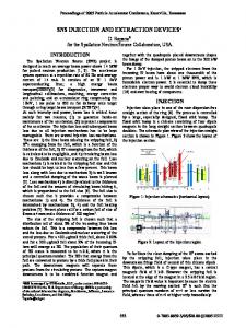
INTRODUCTION The fast beam extraction will be a one-turn, two-step process. A set of fourteen full-aperture kickers will eject the beam vertically from the accumulator ring into the extraction septum gap. Seven of the extraction kicker magnet sections will be at up stream of a vertical focusing, horizontal defocusing narrow quadrupole doublet, and seven down stream of it. The extraction septum will be located 2.13 m down stream of the last kicker magnet section. Figure 1 shows the mechanical layout of kicker magnet sections and quadrupole doublet at extraction straight section.
Figure 1: Extraction kicker magnets section layout. The septum will horizontally deflect the beam by 16.8° into Ring to Target Beam Transport (RTBT) Line. Additional straight section space is reserved for two more extraction kicker modules to allow 1.3 GeV upgrade. The updated system specification is listed in Table 1.
DESIGN CONCEPTS The SNS accumulator ring beam extraction fast kicker system is a high repetition rated pulsed power system. At 60 pulses per second repetition rate, the number of pulses per year of operation exceeds 1.9 x 10⁹. Therefore, all pulsed components and subsystems must have a designed pulse lifetime of multi- billion shots under specified operation conditions. The system demands high peak power as well as high average power. It is necessary to use modularization approach to divide the magnetic load, ease the peak output power per modulator, and simplify production. Usually the beam extraction area is high in radiation level. The components and systems inside the
1810
___________________________________________
* SNS is managed by UT-Battelle, LLC, under contract DE-AC0500OR22725 for the U.S. Department of Energy. SNS is a partnership of six national laboratories: Argonne, Brookhaven, Jefferson, Lawrence Berkeley, Los Alamos, and Oak Ridge. #
[email protected]
Proceedings of EPAC 2004, Lucerne, Switzerland
accumulator ring tunnel will not be accessible during beam operation, and the residual radiation level might prohibit immediate access after cease of beam. To achieve high system maintainability and operability, the high voltage modulators have to be located outside the accumulator ring tunnel. All components used inside beam tunnel shall be radiation hardened. The lumped magnet structure was chosen for its structure simplicity and high reliability. Among many physical and technical challenges, the uncontrolled beam loss is the primary concern of the high intensity proton machine. The resistive impedance caused instability is one of the main factors attributed to beam loss. A 25 Ω beam impedance termination well matched to the modulator output pulse cable impedance is required in kicker design. A design based on Blumlein pulser topology, as shown in Figure 2, was chosen for it can simultaneously satisfy all physics and engineering requirements. In this design a Blumlein voltage doubler and a full reflection at kicker magnet to double the current enhance the system performance by a factor of four. This places all components in the commercially available range; hence the system design is highly cost effective. RING C=5NF L=195NH Z=6.25 OHM
SATURABLE INDUCTOR 50 OHM 50 OHM
HV INPUT
25
MAGNET CT
CT SERVICE BUILDING
Figure 2: Simplified schematic diagram of modulator.
hollow-anode thyratron, a PFN reverse diode stack, an input reverse protection diode assembly, a charging resistor, a beam impedance termination resistor stack, a high voltage divider, a high voltage relay, and a saturable ferrite ring stack. Low inductance structure design as well as use of low inductance components is essential for pulsed power system construction. The thyratron switch and the beam impedance termination resistor have coaxial metal screen enclosures to lower the assembly inductance. The series inductance of the pulse capacitor is about 15 nH, which is cancelled out by the 20 nH estimated mutual coupling inductance of adjacent PFN cells. Reducing the series inductance of the capacitor is important in lowering pulse flat top ripples. The saturable inductor is commonly used for dark current suppression and pulse rise time sharpening. It also isolates the impedance termination resistor from rests of the modulator structure to preserve the impedance matching. The measurement result confirms the design principle. A major mechanical design issue is the cooling system. The modulator will generate 10,000 watts of heat when operates at 60 Hz. Most of the heat is generated in the resistor pack. To remove this heat, the 310 gallons of insulating transformer fluid in the tank was used as a cooling agent. A system of distributed flow paths, which consists of a circulating pump, filter, a water cooled heat exchanger, and flow control devices, was used to circulate the transformer fluid between the PFN components and a water cooled heat exchanger so as to cool the PFN (Fig. 4).
MECHANICAL AND ELECTRICAL CONSTRUCTION The fourteen high voltage modulators will be housed in a service building. The modulator internal structure is shown in Figure 3.
Figure 4: Pulse Forming Network Cooling System.
Figure 3: High voltage modulator internal portion. The main electrical components of the Blumlein modulator include two discrete components PFNs, a
The transformer fluid is pumped out from the gear pump then branched to 4 paths, three flowing into the bottom, and one flows into the top of the PFN then through an internal hose to cool the resistor pack. The pumping back is from 3 paths on the top of the PFN. Each path that flows into PFN has a flow control valve, a flow rate gage and a check valve. The control valve is used to control flow rate in each path. The check valve is to safe guard the tank. If any burst or accident occurs in the piping system, only the fluids in the pipe will spill out. No fluids in the tank will spill out.
1811
Proceedings of EPAC 2004, Lucerne, Switzerland
The transformer fluid, Dow Corning 561, is a Polydimethysiloxane (PDMS) silicon fluid. Its viscosity is about 50 cSt, which is higher than the mineral oil. But unlike mineral oil, PDMS fluid is not a good lubricant for metal-to-metal contact. To circulate this viscous fluid, gear pump with steel gear is not suitable for this fluid. On the other hand, PDMS fluid is one of the best lubricants for fiber and plastic gear. So, after an initial failure of a steel gear pump, a Polyphenylene Sulfide (PPS) plastic gear pump was used to circulate this fluid. This pump was running smoothly. It has accumulated about 100 hours of running time without any sign of wear out or problem. Two large vacuum chambers will each contain seven kicker magnet sections. Figure 5 demonstrates the magnet chamber layout. The magnet material is CMD5005 ferrite.
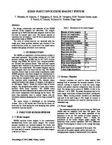
units are very well within the specification. Figure 6 shows the load current waveform of the first production modulator measured at 35 kV operating voltage.
Figure 6: The load current waveform of the first production modulator at 35 kV. As of the date, one prototype and five production modulators have been built. The prototype unit and first production unit were intensively tested at Brookhaven National Laboratory. The subsequent four production modulators have been received at Oak Ridge National Laboratory, and another two are ready to be tested. Rests of the production units are in the construction process. Figure 5: The magnet vacuum chamber.
ACKNOWLEDGEMENT
PERFORMANCE TEST AND PRODUCTION
We would like to express our appreciations to Mr. W.A. Morris of ISIS, Dr. R. Sheldrake of E2V, Mr. R. Cooper and Mr. R. Hartsock of General Atomics for their expert advice and technical support.
One prototype high voltage modulator was built at BNL, fourteen production units are being constructed by industry vendors. The prototype modulator, charging power supply, and kicker magnet were successfully tested up to 50 kV, which is 143 % of 35 kV design specification. The prototype modulator passed all high voltage tests and accelerated lifetime tests at or above 35 kV specified operating voltage. The total high voltage testing time of the prototype unit has exceeded 600 hours at level on or above 35 kV level. The high voltage and accelerated lifetime test of production units are summarized in Table 2. Table 2: Production test standard 75 kV 35 kV 40 kV 45 kV
214 % of spec. 100 % of spec. 114 % of spec. 129 % of spec.
DC Pulse Pulse Pulse
Hi-pot 60 Hz 60 Hz 30 Hz
2 minutes 16 Hours 8 Hours 2 Hours
A modulator is accepted after passing all above tests without failure and interruption. Utilizing industry expertise brings in modernized construction techniques. The production quality is rather satisfactory. The load current waveforms of production
REFERENCES [1] J. Wei, “Synchrotrons and accumulators for highintensity proton beams”, Reviews of Modern Physics, vol. 75, pp. 1383-1432, October 2003. [2] J. Wei, “Low-loss design for high-intensity accumulator ring of the Spallation Neutron Source”, Physical Review special Topics – Accelerators and Beams, vol. 3, 080101 (2000). [3] W. Zhang, J. Sandberg, et al., “A New Conceptual Design of the SNS Full Turn Fast Extraction Kicker Power Supply System”, Proceedings, 2001 Particle Accelerator Conference, June 2001, pp. 3714-3716. [4] H. Hahn, “Impedance Measurements of the SNS Extraction Kicker”, BNL/SNS Technical Note #135, 2004. [5] W. Zhang, J. Sandberg, et al., “High Power Fast Kicker system for SNS Beam Extraction”, Conference Record of the Twenty-Fifth International Power Modulator Symposium and 2002 High Voltage Workshop, June 30-July 3, 2002, pp 262265.
1812