So Many States, So Little Time: Verifying Memory Coherence in the Cray X1∗ Dennis Abts∗
[email protected]
Steve Scott∗
[email protected]
∗
Cray Inc. P.O. Box 5000 Chippewa Falls, Wisconsin 54729
Abstract This paper investigates a complexity-effective technique for verifying a highly distributed directory-based cache coherence protocol. We develop a novel approach called “witness strings” that combines both formal and informal verification methods to expose design errors within the cache coherence protocol and its Verilog implementation. In this approach a formal execution trace is extracted during model checking of the architectural model and re-encoded to provide the input stimulus for a logic simulation of the corresponding Verilog implementation. This approach brings confidence to system architects that the logic implementation of the coherence protocol conforms to the architectural model. The feasibility of this approach is demonstrated by using it to verify the cache coherence protocol of the Cray X1. Using this approach we uncovered three architectural protocol errors and exposed several implementation errors by replaying the witness strings on the Verilog implementation. 1
Introduction
Distributed Shared Memory (DSM) multiprocessors [1, 2] are capable of scaling to large processor counts while providing a flexible programming model, allowing the programmer to treat the memory system as a large, logically shared memory. This programming abstraction, however, comes at the expense of additional hardware complexity to handle the implicit transfer of data as it migrates through the extended memory hierarchy that spans from the load-store unit of a given processor through multiple levels of cache, and possibly across multiple nodes which communicate over an interconnection network (Figure 1). This extended memory hierarchy must be kept consistent by ensuring that writes (stores) are propagated through the memory hierarchy. This cache coherence problem is solved by either software or hardware cache coherence protocol that explicitly manages the state of the memory hierarchy to ensure that data is coherent across the entire memory system. The design of an efficient coherence protocol is extremely challenging and, as Lenoski and We∗ The Cray X1 was referred to as the Cray SV2 during its research and development phase.
David J. Lilja†
[email protected] †
University of Minnesota Electrical and Computer Engineering Minnesota Supercomputing Institute Minneapolis, Minnesota 55455
ber [3] point out, “. . . unfortunately, the verification of a highly parallel coherence protocol is even more challenging than its specification.” The focus of this paper is on the verification of the directory-based hardware cache coherence mechanism employed by the Cray X1. We treat the verification problem at two levels of abstraction: 1) architectural verification of the cache coherence protocol, and 2) verification of its corresponding Verilog implementation. Unfortunately the state space of a cache coherence protocol is enormous. Thus, random testing of the implementation provides very little confidence that the protocol state space has been sufficiently covered. Our method extracts a formal execution trace of the protocol state space during formal verification of the architectural model. Then, we replay the formal execution trace, called a “witness string,” on the Verilog RTL implementation running on a logic simulator. This approach allows us to automatically generate high quality simulation traces by avoiding high fraction of redundant states visited during a random simulation. An individual witness string has no redundant states. This allows the Verilog simulations to be guided by the formal verification of the architectural model increasing confidence that the implementation conforms to the architectural model.
Figure 1: An abstraction of the hardware in a DSM multiprocessor. Control of the memory system is carried out by a finite-state machine (FSM) at each level of the memory hierarchy. The FSMs communicate by exchanging packets. Node 1 P1
L1 $
L2 $
Mem
Router
Node 2 P2
FSM
FSM
FSM Dir
L1 $
L2 $
Mem
Node n Pn
FSM
FSM
FSM Dir
Router
Interconnection Network
L1 $
L2 $
Mem
Router
FSM
FSM
FSM Dir
Figure 2: Two processors, P0 and P1 , accessing a shared variable X. The memory directory (MD) erroneously removes one of the processors from the sharing set (after processing the SupplyShared(X) message) causing a potential data coherence problem.
Memory Directory
X:Invalid 1) X:Pending 2) X:Exclusive 4) X:ShClean
X:Invalid 3) X:Pending 6) X:ShClean 7) X:Pending 8) X:Exclusive
P0
P1
3 Read(X)
6 ReadSharedResp(X)
7 Upgrade(X)
8 GrantExclusive(X)
X : Noncached X : Exclusive {P0 } X : PendFwd X : Shared {P1} X : Exclusive {P1 }
2 ReadExclResp(X)
1 ReadMod(X)
1) 3) 5) 7)
4 FwdRead(X)
Memory Coherence The notion of cache coherence is widely used, but there is no universally accepted definition of what this means. Censier and Feautrier stated that a memory system is coherent if the value returned by a read is always the value of the latest write with the same address [4]. But what is the “latest” write in a distributed system? And what guarantees are there regarding the ordering of reads and writes to different addresses? Avoiding this confusion requires a clean separation between architecture and implementation. The memory consistency model (MCM) is the architectural model that defines how the memory system should behave with regard to ordering of reads and writes by different processors to different memory addresses, possibly including the effect of various synchronization primitives. There are a variety of memory consistency models, including sequential consistency [5], processor consistency [6], release consistency [7] and Total Store Order [8]. The cache coherence protocol and associated hardware structures and logic are what implement a given memory consistency model. Any system that allows multiple cached copies of a memory line will need some mechanism to propagate write values in order to satisfy most MCMs. To verify that a system correctly implements its MCM, one could simulate the system looking for explicit violations of the MCM. While this is theoretically sufficient to determine correctness, it is often not practical or effective, given the enormous state space involved. By using knowledge of a specific implementation of an MCM, it is possible to detect errors in the implementation, even if they have not resulted in violations of the MCM Consider a simple example (Figure 2) from a directory-based coherence protocol very similar to that used in the Cray X1. In this example we have two processors, P0 and P1 and a memory directory (MD). The MD is the data structure used to maintain the set of sharers and access permission to a cache line. The arcs in Figure 2 represent coherence messages between the L2 cache controller and the MD. All references in this example are for the same physical address, X. Each coherence message is given a timestamp. For the purpose of this example, we make a simplifying assumption that the order in which messages are sent is the order in which they are received, otherwise we would need a timestamp when the message is sent and a timestamp indicating when the message was received. When the message causes a state change at the controller the new state is recorded with a timestamp next to it to indicate which message caused the state change. At time 1w processor P0 issues a ReadMod(X), for a cache line read with intent to modify address X. As a result, P0 ’s cache state transitions to Pending. The MD responds at time 2w by adding P0 to the sharing set, sending a ReadExclResp(X) message with the cache line and transitioning to the Exclusive state. Upon receipt of the ReadExclResp(X) the L2 cache at P0 transitions to the
5 SupplyShared(X)
2
Exclusive state to indicate ownership of the cache line. Next, at time 3wP1 sends a Read(X) request and transitions to the Pending state. The MD receives the Read(X) request and transitions to the PendFwd state sending a FwdRead(X) intervention to the owner of the cache line at time 4w. Upon receipt of the FwdRead(X) message, the L2 cache controller transitions to the Shared state and at time 5w sends a SupplyShared(X) response to the MD. The MD receives the SupplyShared(X) message and transitions to the Shared state, adds P1 to the sharing set and sends the ReadSharedResp(X) to P1 at time 6w.
Suppose there exists an error in the protocol specification such that after processing the SupplyShared(X) message received at time 5w, the MD erroneously removes the previous owner, P0 , from the sharing set (clearing its presence bit). The correct state of the MD should be X: Shared {P0 , P1 } indicating both caches are sharing the data for address X. At this point, after receiving the ReadSharedResp(X) at time 6w, if we ask ourselves “is the memory system coherent?” the answer is not entirely clear. Suppose that P1 requested an Upgrade(X) request at some later time, say time 7w, to make the line writable. When the directory receives the Upgrade(X) request it will examine the sharing set and, since there appears to be no other sharers, will grant exclusive access to the line by sending a GrantExclusive(X) message to P1 ’s L2 cache controller at time 8w. Now, because of the protocol error that
occurred between time 5wand time 6w, when P1 writes to the Exclusive cache line those writes will not be propagated to P0 ’s cache which still has access to the line in the ShClean state. On the other hand, it is possible for P0 to evict X from its cache after time 6w(or never read the value from X again) and effectively elude the malignant coherence error. For any given execution, correct behavior requires only that the implementation conforms to the memory consistency model. However, as the example in Figure 2 illustrates, it is possible for a program execution to obey the MCM yet experience an error in the hardware that could lead to a future violation of the MCM. This indicates that the hardware will not be correct for all program executions. Ideally, we would like to ensure that the memory consistency model is obeyed for all possible program executions. However, the vast search space that would entail makes exhaustive search for a violation of the MCM impractical. We can significantly increase the probability of finding an error in a design by understanding the mechanisms used to implement the MCM and searching for errors in the mechanisms before they result in violations of the MCM. Using this approach, we define several hardware correctness properties specific to the X1 implementation; while these properties are not universal, other implementations are very likely to require a similar set of correctness properties. These correctness properties take the form of invariant expressions, which can be checked during a formal verification of the cache coherence protocol or a simulation of the Verilog implementation. 3
Overview of the Cray X1 Memory System
The Cray X1 is a DSM multiprocessor with a vector ISA, capable of scaling to thousands of processors. The X1 memory system is a significant departure from that of its predecessors and hence warrants further elaboration. Each X1 node consists of four multi-stream processors (MSPs) and 16 memory directory (M) chips. Each MSP consists of four single-stream processors (SSPs) and a shared Ecache. The MSP is implemented with four processor (P) chips and four Ecache (E) chips colocated on a multi-chip module. Any MSP may make references to any physical address in the system. However, only references made within the node are cached locally in the external cache (Ecache) and data cache (Dcache) within the SSP. Although the caching domain is restricted to a single node, the X1 memory system is globally cache coherent. All requests, local or remote, are processed by the cache coherence engine at the home node (the node where the physical memory exists). The P chip is a semi-custom ASIC where the functional units are custom CMOS and the supporting logic for the pipeline control, dcache, load/store unit are implemented using standard cells. The E and M chips are implemented using standard cell ASIC technology with six metal layers. The P chip contains 41.5M transistors
Table 1: Messages from chip-to-chip are sent as packets. Chips Commands P to E Read, ReadMod, ReadUC, ReadShared, ReadSharedUC, SWrite, SWriteNA, VWrite, VWriteNA, FetchAdd, FetchCSwap, FetchAndXor, AtomAdd, E to M
M to E E to P
AtomAndXor MRead, MReadMod, MReadShared, MGet, MPut, FlushAck, InvalAck, SupplySh,SupplyExclSh, SupplyDirtyInv, UpdateAck, UpdateNAck ReadExclResp, ReadSharedResp,GetResp, FwdRead, FwdReadShared, FwdGet, FlushReq, WriteComplete, Inval, Update PReadResp, PInvalidate
on a 16.5mm die. The E chip has 44.5M transistors on a 17.4mm die and the M chip has 31.8M transistors occupying a 16.5mm die. Each MSP, therefore, has (41.5 + 44.5)×4 ≈ 344M transistors housed on a multi-chip module. 3.1
Chip-to-Chip Communication
The finite-state machines at each level of the memory hierarchy communicate by exchanging messages encoded as packets (Table 1). The packets flow on communication channels between the P chip, E chip and M chip. The physical communication channels are organized as three virtual networks, VN0, VN1 and VN2, in order to avoid deadlock in the interconnect. Requests are sent on VN0. Responses, interventions and invalidates are sent by the memory directories on VN1. Writebacks, eviction notices, and responses to interventions are sent on VN2. 3.2
Memory System Commands
The memory system commands support scalar and vector reads and writes, as well as atomic memory operations (AMOs). X1 supports two types of AMOs: result returning (FetchAdd, FetchCSwap, FetchAndXor) and nonresult returning (AtomAdd, AtomAndXor). The processor request includes an allocation hint which allows the requestor to indicate whether the data should be allocated as shared, exclusive, or non-allocating. The commands with the *UC suffix are uncached in the Dcache. Commands ending in *NA (ReadNA, SWriteNA, VWriteNA) are non-allocating and do not allocate in either the Ecache or Dcache. The memory system commands are exchanged from chip-to-chip on the virtual network (Table 1). Requests use the mask field of the packet to indicate which word(s) of the cache line to operate on. Each request uses a transaction identifier (TID) which is sent along with the request as it traverses the memory system. The TID is used to index into many of the auxiliary data structures used by the memory system.
Table 2: Memory system states for the Dcache, Ecache, and memory directory. States Dcache Valid, Invalid Ecache Invalid, ShClean, ExClean, Dirty, Memory Directory
3.3
PendingReq, WaitForVData, WFVDInvalid Noncached, Shared, Exclusive, PendMemInvWrite, PendMemInvPut, PendMemExclusive, PendInvalPut, PendInvalWrite, PendFwd, PendDrop
Cache Organization and Memory Directory
The X1 has two levels of cache memory, Dcache and Ecache. The memory directory (MD) tracks the set of Ecaches with access to each cache line. 3.3.1
Dcache
The Dcache is a set associative write-through cache with 32-byte line size. The Dcache has only two states: Valid and Invalid. It makes no distinction between Valid and pending lines. Cache lines are marked Valid as soon as they are allocated. An associative match against earlier queued requests informs a new request when a valid line has not yet returned from the memory system, in which case the new request is enqueued behind the earlier request that initiated the Dcache fill. 3.3.2
Ecache
The Ecache is a set associative writeback cache with 32-byte line size and least recently used (LRU) replacement policy. The Ecache maintains inclusion over its local Dcaches using a 4-bit inclusion vector associated with the state of each line. The Ecache states are given in Table 2. The ShClean state is used only when the line is read only access. The ExClean state indicates exclusive access to the line, however, it has not yet been modified. When the line is modified it becomes Dirty. The PendingReq state is entered when waiting for a cache line response from memory. The X1 decouples the vector address and data, so the Ecache enters the WaitForVData state when it receives a VWrite request with the cache line address, but is still awaiting the vector write data packet. The WFVDInvalid state is used only when the Ecache receives an Inval packet from the directory while in the WaitForVData state. In which case, when the Ecache receives the vector data it will discard the data and transition to the Invalid state. Ecache evictions The X1 supports non-silent cache evictions to prune the sharing set and reduce the likelihood of a phantom invalidate. An evicted line will send an eviction notice message to the directory depending on the current state. If the state of the evicted line is Dirty a Writeback message is sent. Otherwise, a Drop or Notify message is sent if the state is ShClean or ExClean, respectively.
3.3.3
Memory Directory
Each M chip contains four memory directories. The memory directories are sufficiently large and associative to track the contents of all Ecache on the node simultaneously. This avoids the complication of evicting directory entries and invalidating the Ecache lines due to a capacity miss. Each memory directory is connected to two memory managers (MMs) which control the Rambus memory channels. Each directory entry has a tag, state and sharing vector associated with it. The sharing vector is a simple 4-bit vector which indicates the Ecaches that are caching the line. The directory states are given in Table 2. Write completion The directory collects InvalAck messages from the sharing Ecaches and sends a WriteComplete to the requesting Ecache once all invalidates have been successfully acknowledged. Only after the Ecache receives the WriteComplete message is the write deemed globally visible. A write is considered globally visible when no processor can read the value produced by an earlier write in the sequential order of writes to that location. Replay queue Both the E and M chips maintain a data structure called the replay queue (RQ). The RQ is used when an incoming request arrives at the Ecache or memory directory while the line is in a transient (pending) state. The new request is enqueued on the RQ, where it will be “replayed” after the transient state is resolved. The entries in the RQ are maintained as a linked list according to the requested address. So, when a request is replayed from the RQ, a simple pointer chase will find the next related entry. Transient buffer When a new request causes a state transition from a quiescent state to a transient state (for instance a transition from Noncached to Pending) the request is stored in a transient buffer (TB) indexed by the requesting TID. When the message arrives that allows the transient state to be resolved (for example, transition from Pending to Exclusive) the request is removed from the transient buffer and serviced. Each TB entry contains a buffer capable of holding one cache line. This buffer is always marked “empty” when the TB entry is allocated, and can be filled (and marked as “full”) by a Writeback or Supply* message from the Ecache. Then, the RQ is “replayed” to maintain ordering of any new requests that arrived while the cache line was in a transient state. The TB line buffer may subsequently be used to provide data for a request that is being replayed from the RQ. 3.4 X1 Memory Consistency Model X1 provides a relaxed memory consistency model (MCM) that describes how the programmer must view the shared memory in order to provide predictable program behavior. It is described in the X1 instruction
set architecture (ISA) and provides a set of guarantees and a set of synchronization instructions to the programmer. In general, the X1 MCM provides very few ordering guarantees. They include:
4.1
Data Coherence
We indirectly capture the notion of data coherence by making some assertions about the state of the memory directory and caches.
1. Single stream program order is preserved for scalar writes to the same word in memory. Vector and scalar writes are not ordered unless an Lsync instruction is explicitly used to provide ordering among vector and scalar references.
Property 1 If an address, a, is in the “noncached” state at the directory and there are no messages, m, inflight from processor p to Dir(Home(a)) then processor p must have address a in an invalid state.
2. Writes to the same address are serialized. That is, no two processors can observe a different ordering of writes to that location.
∀a ∀m ∀p Noncached(Dir(Home(a))) ∧ ¬ InFlight(m, p, Home(a)) ⇒ Invalid(a, p)
3. A write is considered globally visible when no processor can read the value produced by an earlier write in the sequential order of writes to that location. 4. No SSP can read a value written by another MSP before that value becomes globally visible. All other ordering between SSPs and MSPs must be provided by explicit memory synchronization instructions, Msync and Gsync. The Msync primitive is used as a lightweight synchronization operation among multiple MSPs in the same node. The Gsync is a global synchronization across all nodes in the machine. 4
Correctness Properties
Ultimately, correctness is defined by the memory consistency model (MCM) as described by the instruction set architecture (ISA). The cache coherence protocol is a critical piece of the MCM responsible for propagating writes, although other hardware such as arbiters, replay queue, and virtual network buffers, are equally important in correctly implementing the MCM since a hardware error in any one of these components could result in a violation of the MCM. For example, a hardware error in an arbiter may allow subsequent memory references to overtake earlier ones and thus violate the property of preserving individual program order. Although the properties we define are implementation-specific to the X1, it is very likely that the semantics of these properties would apply to other systems as well. Showing that a cache coherence protocol is correct is nontrivial, as there are many aspects to “correctness,” and the protocol state space is very large. Our approach is to formally model the protocol and prove that a collection of well-defined, fundamental properties hold over the state space. While these properties take into consideration the implementation details of the X1 cache coherence protocol, we expect that most coherence protocols would require similar properties. We use several predicates and functions 1 to describe the state of the caches, directory, and interconnection network. 1 Predicates are designated by bold typeface and evaluate to a logical true or false. Functions return a value and are in sans serif typeface
where a is an address, p is a processor cache, and m is a message. The function Home(a) returns the identity of the memory directory responsible for managing the address a. Likewise, the function Dir(d) returns the state of the memory directory (access permission and sharing set) for a given memory directory d. Property 2 If an address, a, is present in cache, p, then it must be included in the sharing set by the directory. ∀a ∀p Present(a, p) ⇒ SharingSet(Dir(Home(a)), p) The SharingSet predicate returns true if the memory directory knows that address, a, is present in cache, p. Put another way, the set of caches with address a present is a subset (⊆) of the sharing set at the directory. While these two properties do not explicitly address the read-the-latest-write aspect of memory coherence, they do ensure that the memory directory is properly maintaining the sharing set, an essential ingredient for memory coherence. Property 2 allows a cache line to be tracked by the memory directory, even if it is no longer present in the cache. For instance, if a cache line is evicted there will be some transient time between the eviction notice being sent and the memory directory removing the cache from the sharing set. As such, the cache could receive a “phantom” invalidate from the directory for a cache line that is no longer present. 4.2
Forward Progress
Ensuring forward progress requires every memory request to eventually receive a matching response. Since all coherent memory transactions occur using requestresponse message pairs, we can exploit this fact by formally stating: Property 3 Each request must have a satisfying response. ∀x Request(x) ⇒ ∃y Response(y) ∧ Satisfies(y, x) Moreover, the forward progress property (Property 3) encapsulates the notion of deadlock and live-lock avoidance by requiring each request to eventually receive a matching response. Deadlock is the undesirable condition where it is impossible to transition out of the
Exclusivity
The coherence protocol enforces some access permissions over the shared-memory to ensure that there are never two or more processors with “exclusive” (write) access to the same memory block. This single-writer property can be stated as: Property 4 Two different caches, p and q, should never have write access to the same address, a, at the same time. ∀a ∀p ∀q IsDirty(a, p) ∧ q 6= p ⇒ ¬ IsDirty(a, q) This property ensures that no two processors p and q are able to have memory block a in their local memory hierarchy in the “dirty” state 2 at the same time. 4.4 Unexpected Messages If the coherence protocol is not fully specified it is possible to get an unexpected message making it possible for an FSM to receive an input message for which there is no corresponding entry in the specification table. For example, consider the following example encoding of an FSM: ... Case State = Dirty Case InMsg = PrRead send(P, ReadResp) Case InMsg=PrWrite UpdateCache() send(P, WriteComplete) ... Default Error(UnexpectedMsg) Case State = Shared ...
The “Default” case is used to trap unexpected messages, which are probably the result of an oversight in the protocol specification or some corner case that the protocol designer overlooked.
5.1
Formal Verification
When constructing the formal model it is necessary to strike a balance to attain sufficient detail necessary in making the model accurate while scaling down the model to make an exhaustive search of the state space tractable. This balancing act, unfortunately, is subject to the perils of trial-and-error. We started with a fairly detailed system model and pruned away details and made abstractions where appropriate to make the size of each state relatively small. The space-complexity of the protocol verifier will be related to the size of each state. We began with a detailed model that included the Dcache and load/store unit. However, through experimentation we arrived at a model that omitted the Dcache and load/store unit. Instead, the model included a fairly detailed representation of two slices of an MSP, each containing an Ecache, memory directory, replay queue, output request buffer, memory manager, virtual network buffers, and a simple processor model that issues requests and consumes response packets. Each Ecache had a single cache tag, with single bit of data. The virtual network model was complicated by the requirement of VN2 to always be able to sink an
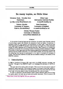
Figure 3: The number of reachable states and time required to search explodes as the processors are allowed to issue more commands. 200
Reachable States Time
700000 600000
150
500000 400000
100 300000 200000
50
Read, SWrite, ReadShared, ReadMod, AMO, VWrite, ReadUC, ReadNA
Read, SWrite, ReadShared, ReadMod, AMO, VWrite, ReadUC
Read, SWrite, ReadShared, ReadMod, AMO, VWrite
Read, SWrite, ReadShared, ReadMod, AMO
2 Some protocols use the terms “dirty” or “exclusive” state. We assume that the predicate will return true if the cache line is either dirty or exclusive.
Read, SWrite, ReadShared, ReadMod
To verify the coherence protocol at an abstract level, we used the Murϕ formal verification environment [9].
Read, SWrite, ReadShared
Verification Results
Read, SWrite
5
Read
100000
Time (seconds)
4.3
The coherence protocol is specified as several humanreadable text files. These files are then read by an internally developed protocol compiler that automatically generates the finite-state machine descriptions in the Murϕ description language. The Murϕ compiler is then used to create the intermediate C++ description which is compiled and linked into the protocol verifier. We simulated the Verilog RTL implementation using both Synopsys VCS logic simulator and Gensim cyclebased logic simulator. We replayed witness strings from the Murϕ verification on the logic simulator exposing several bugs with the implementation.
Reachable States (millions)
current global state. Live-lock, on the other hand, is a cycle of states that prevents forward progress. The predicates Request(x) and Response(y) evaluate to a logical true if x is a request and y is a response, respectively. Similarly, the predicate Satisfies(y, x) evaluates to a logical true if y satisfies x. For example, the predicate Satisfies(y, x) would consult the transition relation for the coherence protocol to determine if y was an expected response to request x. Clearly, this property ensures forward progress by ensuring that a request is never starved or indefinitely postponed.
Figure 4: A protocol error that was discovered using Murϕ . Had this error gone undetected it would have resulted in a loss of memory coherence. Pseudo-Node 2
Pseudo-Node 1
Y
X Shared : E2 (2) Shared : E1, E2 (5) Shared : E2
Shared : E1 (6) Shared : E1 (8) Noncached 8 6
M1 2a
) Y p( ro M
D
) (Y
ad Re M
Y)
3
1a
M2 6a
5
MDrop(X)
MRead(X)
ReadSharedRsp(X)
2
sp(
dR
4b
1b
Y : ShClean (1) X : PendingReq (3) X : ShClean (4) Y : PendingReq (7) Y : ShClean
e har
Re
adS
X : ShClean
4a 7
E1 Read(Y)
4c
E2
1c
PInvalidate(Y)
Read(X)
3a
PInvalidate(X)
4
PReadResp(X)
1
Proc0
Proc0
incoming message. Otherwise, VN0 and VN1 each were a single entry buffer. However, VN2 required an additional buffer to act as a staging area to satisfy the requirement that we be able to sink a VN2 message. The size of each state in the X1 Murϕ model is 1664 bits and consists of 140 rules. At each state of the search, the verifier chooses among the 140 rules in the model to see which rules are eligible to execute (the predicate of the rule condition is true). A brute force search of every state would yield 21664 states! Fortunately, a much smaller number of states are actually reachable (Figure 3). The protocol state space is ≈200M states, requiring almost 750000 seconds (over eight days) to explore! However, initially we did not know the upper bound on the search, so we started by only allowing each processor to issue only Read commands. This seemingly trivial case yielded a reachable state space of 8030 states and uncovered a critical error in the protocol (Figure 4). The arrows in Figure 4 show the packets exchanged between chips, with a square marker indicating the time the packet was sent from the chip and a circular marker indicating the time the packet was received. Initially, we see that the processor at pseudo-node 1 has address Y in the ShClean state. A Read(X) request at event time 1 results in an eviction of Y from the E1 cache. The eviction causes a PInvalidate(Y) packet to be sent to the Dcache in the processor and an MDrop(Y) eviction notice to be sent to the directory. At the same time, the MRead(X)
request is sent to the directory, which responds with a ReadSharedResp(X) response. Then, at event time 4 the processor issues a Read(Y) request to the E1 cache. The E1 cache evicts X and sends a PInvalidate(X) to the Dcache in the processor and an MDrop(X) eviction notice to the directory. At the same time, the E1 cache sends the MRead(Y) request to the directory, which responds with a ReadSharedResp(Y). Finally, the MDrop(Y) request from the eviction notice sent at time 1b reaches the directory at event time 8. When it receives the eviction notice, the directory removes E1 from the sharing set and checks to see if there are any remaining sharers. Since there are none, the directory transitions to the Noncached state. At this point, any stores to Y will not be propagated to the E1 cache, resulting in a loss of memory coherence. While it would have been difficult to construct a test to uncover the complex sequence of events that led to this error, our formal verification approach was able to discover it automatically. 5.2
Logic Simulation
The objective of the implementation verification is to run the “witness strings” generated by the Murϕ formal verification on the Verilog RTL implementation of the hardware. The Verilog is compiled and simulated using an internally developed tool called Gensim [10]. The witness strings are encoded using a high-level verification environment called Rave [11, 12], which is
Figure 5: An example of a witness string generated by the Murϕ formal verification tool. -------------------------------------------------Issuing scalar request Read from Proc_1 of Node_1 -------------------------------------------------Quiescent: 1 E1(1:ShClean)