Future PCS cellular networks will mainly be driven by high quality channels, high .... Let f1;2;:::;Ng, be the set of active transmitters using this generic channel,. 4 ...
SOFT AND SAFE ADMISSION CONTROL IN CELLULAR NETWORKS � Michael Andersin
y
Zvi Rosberg
Jens Zander
z
(Oct. '94 - Revised Feb. '95, Nov. '95, Sept '96)
Haifa Research Lab. Science and Technology, IBM Israel MATAM, 31905 Haifa, Israel
This research has been done while the 2-nd author was visiting at the Royal Inst. of Tech. under a grant from ISS '90 foundation, Sweden. y Radio Communication Systems, Royal Institute of Technology, Sweden. z Radio Communication Systems, Royal Institute of Technology, Sweden. �
0
Abstract We study the mobile admission control problem in a cellular PCS network where transmitter powers are constrained and controlled by a Distributed Constrained Power Control (DCPC) algorithm. Receivers are subject to non-negligible noise, and the DCPC attempts to bring each receiver's CIR (Carrier to Interference Ratio) above a given quality target. Two classes of distributed admission controls are considered. One is a Non-Interactive Admission Control (N-IAC), where an admission decision is instantaneously made based on the system state. The other is an Interactive Admission Control (IAC), under which the new mobile is permitted to interact with one or more potential channels before a decision is made. The algorithms are evaluated with respect to their execution time, and their decision errors. Two types of errors are examined. Type I error, where a new mobile is erroneously accepted and results an outage; and type II error, where a new mobile is erroneously rejected and results in blocking. The algorithms in the N-IAC class accept a new mobile, if and only if the uplink and the downlink interferences are below certain corresponding thresholds. These algorithms are subject to errors of type I and type II. In the IAC class, we derive a Soft and Safe (SAS) admission algorithm, which is type I and type II error free, and protects the CIRs of all active links at any moment of time. A Fast-SAS version which is only type I error free, is proposed for practical implementation, and evaluated in several case studies.
Keywords: PCS, Wireless, Constrained Power Control, Mobile Admission.
1
1 Introduction Future PCS cellular networks will mainly be driven by high quality channels, high bandwidth utilization, low power consumption and e�cient network management. Constrained power control (up-link and down-link) is one of several major techniques which is being studied to address these goals. In PCS, cell sizes are small and transmission power is limited, exposing the receiver to more severe noise compared to larger cells where higher transmission power is used. This has been recently incorporated into the model in [11], where a power constrained control problem in a cellular network with a xed number of users, cochannel interference and receiver noise, has been studied. The model there, and in this study, assumes a stationary link gain matrix, which is reasonable when the power control converges much faster than the link gain changes. The communication channel quality is measured by its Carrier to Interference Ratio (CIR). It is well known that there is a monotonically increasing relation between the CIR and the channel symbol error rate. Thus, driving the CIR to some CIR target, is the same as driving the channel to some capacity target. In practice, the CIR target is determined by the operator based on the error rate which the decoder can tolerate. In a practical situation the number of users is not xed, and mobility, call departures and call arrivals, give rise to various network management problems. One is mobile removals in over-allocation situations which has been studied in [18], [13] and [3]. The dual problem which we study here, is the admission control of a newly arrived mobile. A new mobile requires a base station and a channel, and the admission control has to trade-o� between channel quality, low outage and blocking probabilities. The outage and the blocking probabilities are closely related to the two following types of admission errors. Type I error, where a new mobile is erroneously accepted and results in an outage; and type II error, where a new mobile is erroneously rejected, while it could be supported along with the other active mobiles. This results in a blocking. A building block of our mobile admission algorithms is the Distributed Constrained Power Control (DCPC) which has been proposed in [11]. This power control aims to minimize the transmission powers required to maintain the channel CIRs above pre-speci ed CIR targets. It has been shown in that paper, that DCPC converges to a unique power vector, under synchronously and asynchronously power updates. The latter algorithm is denoted 1
by ADCPC. It has been further demonstrated by numerical examples that asynchronous updates converge faster than synchronous updates. The results in [11] extend previous extensive studies of centralized and distributed power control schemes in [1, 14, 16, 17, 18, 10, 9, 8, 4, 15, 2]. The objective of this paper is to investigate admission control algorithms, and devise a fast and practical distributed algorithm which is based on locally measured information. In general, multiple mobiles may concurrently seek for admission. This can be addressed either by a one-by-one admission type algorithm, or by a multiple admission type. One-by-one and multiple oriented algorithms have been studied in [3] for mobile removals, where it has been demonstrated that one-by-one algorithms outperform multiple oriented algorithms. We argue that a similar phenomenon is also expected for mobile admissions. The main reason in both situations is that when multiple arrivals compete on the same channel, they generate higher cochannel interference which results in higher admission error probabilities. We further argue that concurrent arrivals to the same channel are rare events, since arrivals are Poissonian, admission control must be fast, and each cell has several channels. Therefore we focus only on one-by-one admission algorithms, and drive toward fast execution time. A centralized admission algorithm in a noiseless system with unconstrained powers has been studied in [4]. It has been shown there, that for a given N ? 1 active links, the decision whether to accept or reject a new mobile can \safely" be made by solving N linear equations. By \safe" we mean, that there is a power vector (found by this solution), under which all N mobiles are supported at their CIR targets. The algorithm is centralized and requires the knowledge of the link gain matrix. In this paper we study distributed algorithms of two types. One is a Non-Interactive Admission Control (N-IAC), where an admission decision is instantaneously made based on the system state. The other is an Interactive Admission Control (IAC), under which the new mobile is permitted to interact in one or more potential channels before a decision is made. We focus on the decision whether to accept or reject a new mobile to a given particular channel and cell. The selection of the best cell and channel which may accommodate the new mobile, is beyond the scope of this paper. The N-IAC algorithms are subject to errors of type I and II. These errors are evaluated for several case studies and demonstrate that these algorithms are impractical. This motivates our study of algorithms in the IAC class, where we derive a Soft and Safe (SAS) admission 2
algorithm. The algorithm is type I and type II error free, and protects the CIRs of all active links at any moment of time. This facilitates a safe concurrent execution on multiple downlink and uplink channels and cells. As a result of the apparently slow convergence rate of SAS, we propose a Fast-SAS version which is only type I error free, but is practically tractable and its type II error probability is below an acceptable level. An algorithm similar to SAS has been brought to our attention after a preliminary circulation of this paper. The algorithm, referred to as Distributed Power Control with Active Link Protection (DPC-ALP), has been independently derived in [5]. DPC-ALP is designed around a non-constrained power control, and the constrained case is resolved by a distress action (see below). We rst describe the DPC-ALP algorithm, and then outline the di�erences between DPC-ALP and SAS. DPC-ALP is a multiple admission algorithm which is built on top of a non-constrained distributed power control which has been proposed in [8]. Active mobiles adjust their power levels to maintain a xed safety margin above their CIR target. New mobiles gradually increase their powers in a controlled manner, which prevent the active mobiles from dropping below their CIR targets. In a non-constrained case, when all mobiles can be supported, the active mobiles (under the DCP-ALP algorithm) can always achieve a safety margin by increasing their transmission power. In the constrained power case, DPC-ALP takes the following approach. When an active mobile requires a power above the maximum level, it transmits a distress signal. The new mobiles in its neighborhood, which receive the distress signal, are blocked and cease their transmission. The SAS and DPC-ALP algorithms di�er in several aspects. The rst is by their operational de nition. SAS uses constrained transmitter power control, and active transmitters do not maintain a xed safety margin above their CIR targets. They adjust their power just enough to maintain their CIR targets. The mechanism by which the active links are protected is di�erent than the one used by DPC-ALP. A newly arrived mobile is listening to the pilot signals from all base stations which transmit in the candidate channel, and measures the link gains. It also receives in the pilot signals, each base receiver's noise and the transmission power of its corresponding transmitter. This information is used by SAS to control the transmitter power level of the new mobile. We show that in a reciprocal system, this can be done in a way which protect the active links from dropping below their target CIR, at any moment of time. 3
The algorithms also di�er by their properties. Whereas SAS is type I and type II error free, DPC-ALP may experience type II errors. Furthermore, SAS is protecting the active links at all times, whereas DPC-ALP may fail to do so. Indeed, DPC-ALP may erroneously reject a new mobile because it uses a xed safety margin rather than an ever-shrinking one. This positive xed margin could be the slack required by the new mobile to enter. Furthermore, due to the CIR-balancing property and the random propagation conditions, the new mobile in the vicinity of the bounded transmitter, is not necessarily the one which is the source of the problem. Therefore, the DPC-ALP distress signal may reject the wrong mobile, while leaving in the mobile causing the problem. As a result, the active link may not be protected at all times, and an erroneously rejection may occur. The spectrum utilization under each algorithm is also di�erent. Under DPC-ALP, the active transmitters are updating their transmission powers using the CIR safety margin at all times. This safety margin may result in an under-utilized radio spectrum. Under SAS, active transmitters only react to a new mobile controlled transmission, with no safety margin. Thus, under SAS, over powered transmission instances are transient, and therefore radio spectrum is utilized more e�ciently. SAS and DPC-ALP have slow convergence rate which make their strict version impractical. This issue is left open for further study in [5]. We propose a Fast-SAS version which is based on the observations made in our numerical results. Fast-SAS is type I error free, practically fast, and has a type II error probability below a reasonable value. In Section 2 we introduce the model, in Section 3 we de ne the N-IAC class of algorithms, and in Section 4 the SAS and Fast-SAS. The SAS properties are proven in the Appendix. Numerical results are presented in Section 5, and conclusions in Section 6.
2 System Model We restrict our de nitions to the uplink case (from mobile to base). The downlink is modeled in the same way, with the appropriate notational changes. The link propagation and the receiver noise variables are clearly di�erent, but the model is still the same, and the results in this paper hold true for the downlink case as well. Consider a cellular radio system and let us focus on a generic channel (a speci c frequency or time slot). Assume that channels are orthogonal, so adjacent channel interference is negligible. Let f1; 2; : : : ; N g, be the set of active transmitters using this generic channel, 4
and 0 be the newly arrived mobile requesting to use the same channel. Denote by N = f0; 1; 2; : : : ; N g, the combined set of transmitters, and p = (p0 ; p1; : : :; pN ), the transmission powers used by the mobiles to communicate with their base stations. We will add a time index to the powers, whenever necessary. That is, p(t) = (p0(t); p1(t); : : :; pN (t)). Denote the link gain matrix by G = [gij ], where gij is the gain of the radio link from transmitter j to base i, 0 � i; j � N . All link gains assume values in the semi-open interval (0; 1]. Let � = (�0; �1; : : :; �N ), be the receiver noise vector at the base stations. The noise vector is non-negative, and we further assume that at least one element is positive. The link quality is measured by the Carrier to Interference Ratio (CIR). For a given power vector p, the CIR at the base station used by transmitter i, is given by
i = � + Ppigii g p = � + Ppi a p ; 0 � i � N; i i j :j 6=i ij j j ij j where �i = �i=gii , and
(1)
8 > < gij =gii ; if i 6= j ; aij = > :0; if i = j :
The matrix and the vector of the transformed gains and noises are denoted by A = [aij ] and by � = (�0; �1; : : : ; �N ), respectively. In this paper we slightly generalize the model in [11], and allow each transmitter to have its own CIR target it, and maximum power constraint p�i . We note here, that all the results from [11] continue to hold true under this generalization. Denote by t = ( 0t ; 1t ; : : :; Nt ) and by p = (�p0; p�1; : : : ; p�N ) , the two respective vectors.
For every two vectors v = (v1; v2; : : :; vn), w = (w1; w2; : : :; wn), and square matrix M = [mij ], de ne v w def= (v1 � w1; v2 � w2; : : :; vn � wn), and v M def= [vi � mij ]. We say that a feasible power vector p supports all transmitters at their CIR target t, if and only if p � t (Ap + �) :
That is, the CIR of each receiver i sati es, i � it. The algorithms DCPC and ADCPC update the powers as follows. Given the power vector at time t, p(t), and the set of transmitters updating their powers at time t + dt, U (t), 5
then
8 P > < minfp�i; it � p ((tt)) g = minfp�i ; it(�i + j2N aij pj (t))g ; if i 2 U (t); pi (t + dt) = > : pi (t) ; otherwise : i
i
(2)
Note that U (t) is an arbitrary set. Thus, any asynchronous power update is allowed (subject to some week conditions which exclude in nitely long intervals where a power is not being updated - see [11]). If U (t) = N for every update instance t we obtain the synchronous DCPC version. Otherwise, we obtain the asynchronous version (ADCPC). Also note, that pi(t)gii= i (t) is the interfering power (including the background noise) at receiver i. Since the receiver interference power can be measured, and gii can be detected by the transmitter from the base station pilot signal (assuming a reciprocal system), this algorithm can be implemented in a distributed manner. To exclude impractical cases where a transmitter cannot overcome its receiver background noise, we assume that pi > t�i ; 8 i. It can be shown, using exactly the same proofs as in [11], that for any given t, DCPC and ADCPC converge to a unique positive power vector which is determined by the xed point solution of (3) p = minfp; t (Ap + �)g : A xed point solution to (3) will be referred to as a stationary power vector, and it will become useful to denote it by p�. Observe that when all transmitters can be supported, the DCPC converges to the xed point solution of
p = t (Ap + �) :
(4)
For every subset of transmitters N0 � N , let SN0 be the subset of transmitters which are supported (at their it) under the stationary power vector, given that DCPC runs only with the set of transmitters N0. Note, that this corresponds to a gain matrix and a noise vector which are obtained from A and �, respectively, by removing the columns and the rows that do not correspond to N0. From [11], it follows that
pi = p�i ; 8 i 2 N0 n SN0 :
(5)
Finally, we assume a reciprocal propagation signal model. That is, the uplink gains giju , and downlink gains gijd , satisfy giju = gjid . Note that a reciprocal channel model is an 6
approximation to a real channel, which is very reasonable when no multipath fading is involved.
3 Non-Interactive Admission Control (N-IAC) A primary objective of an admission control algorithm is a fast execution time. The algorithms in the N-IAC class are distributed, based on local information, and make instantaneous decisions. To de ne them we annotate the downlink and the uplink variables by d and u, respectively. Let Iid(t) and Iiu(t) be the interference at receiver i at time t, in the downlink and in the uplink, respectively. Note that each base station i can measure Iiu(t), and each mobile i can measure Iid(t). The interference-based admission algorithm, referred to as MaximumInterference Threshold (MIT), is de ned as follows.
MIT Mobile Admission Algorithm: Upon mobile 0 admission request for a speci c cell and channel at time t, the mobile and its corresponding base station, rst measure the downlink and the uplink interferences, I0d (t) and I0u (t), respectively. Then, the new mobile is accepted, if and only if, I0d (t) � T d and I0u(t) � T u, where T d and T u are given downlink and uplink thresholds, respectively.
When the thresholds T u and T d are system prede ned constants, we say that the corresponding MIT algorithm is Mobile Independent (MI-MIT). When the thresholds are chosen as a function of the newly arrived mobile, we say that the corresponding MIT algorithm is mobile dependent. Note that if a mobile independent MIT algorithm is used, then the natural selection of a cell and a channel is the one with the minimum measured interference. A special mobile dependent MIT algorithm is one which uses the new link gain g0;0, and the maximum transmission powers, p�u0 and p�d0 . Note that in a reciprocal propagation signal model, the uplink and the downlink gains of mobile 0, are both equal to g0;0, and can be measured by the mobile by listening to the base station pilot signal. The MIT algorithm with mobile dependent thresholds set to T d = g0;0p�d0= 0d;a, and to T u = g0;0p�u0 = 0u;a, will be referred to as the Mobile Dependent MIT (MD-MIT) algorithm. Here, 0u;a and 0d;a are admission CIR thresholds for the uplink and downlink, respectively. By this de nition, MD-MIT make 7
decisions by comparing the CIRs 0u(t) and 0d(t), to the corresponding thresholds 0u;a and
0d;a. That is, MD-MIT is a CIR-based algorithm. Clearly, good admission CIR thresholds
0u;a and 0d;a, should be larger than the operational CIR targets. For the MD-MIT algorithm, a natural selection of a cell and a channel is the one with the minimum ratio of the measured interferences I0d(t) ( I0u(t) ) over the link gain g0;0.
Remark 3.1 Observe that the MD-MIT algorithm favors new mobiles which are closer to
the base station, since their link gains g0;0 are typically larger. Further, all MIT algorithms are subject to errors of type I and type II. This motivates the derivation of the SAS algorithm below, which is type I and type II error free.
4 Interactive Admission Control (IAC) The IAC class of admission control algorithms has the potential of making better and safer admission decisions. That is, to prevent CIR deterioration in the active links and to assure acceptance, if and only if all links can be supported at their CIR targets. This is facilitated by permitting the new arrival to interact with the active transmitters using limited power transmissions. In this section we derive a new interactive admission control algorithm, referred to as Soft and Safe (SAS), which achieves the two objectives above. The principal idea is to use a constrained power control scheme with a tighter power constraint on the new arrival. Its power constraint is gradually relaxed until the moment where it can either be rejected or be accepted. With the latter respect, it is similar to the DPC-ALP algorithm proposed in [5]. With DPC-ALP however, the power control runs with the CIR protection margin for the active links at all times. With SAS, the admission control is invoked only when needed. The properties of the SAS algorithm are based on the following Lemmas, whose proofs are given in the Appendix. The de nitions and the discussion below deal with the uplink case, however, the results hold true also for the downlink case after appropriate notational changes. The SAS algorithm is used in the downlink and in the uplink simultaneously.
Lemma 4.1 Let p be a power vector such that p � t (Ap + �) . If � is an additional receiver noise vector satisfying � � � � �, for some � � 0, then p � t (Ap + � + �) , where 8
p = p(1 + �). Lemma 4.1 reveals the following. Assume that we have a stationary power control which supports all mobiles at their CIR targets, and an additional receiver noise is introduced into the channel (e.g., due to a new mobile transmission). If the power vector is boosted by some factor, then the mobiles will still be supported. Clearly, this can be done only if the factor is known and the new powers are below the upper limits. For the next Lemmas, it will be convenient to relate the stationary power vector with its corresponding noise vector �, i.e., p� = p�(�). In the next Lemma we show that p is an over reacting power vector. We further show, that it can be corrected by successive DCPC power updates.
Lemma 4.2 Let p�(�) be a stationary power vector which supports all mobiles under noise condition �. Assume that � is an additional receiver noise vector satisfying � � � � �, for some � � 0. If p�(�)(1 + �) � p , and the DCPC algorithm starts with p� (�)(1 + �) for the receiver noise � + �, then all mobiles are supported at any moment of time. Moreover, p�(� + �) � p�(�)(1 + �) .
Lemma 4.2 suggest to execute the DCPC algorithm after boosting the powers due to the additional receiver noise. Doing so, the power vector could only decrease, leaving room for extra powers which might be required later on. Also, during the DCPC execution, all mobiles are supported. Next we show that p�(�) is monotonic in �.
Lemma 4.3 Let �; �0 > 0, be two receiver noise vectors under which all mobiles can be
supported. If � 0 > �, then p�(� 0) > p� (�), where p�(� 0 ) and p�(�) are the corresponding stationary power vectors.
We assume that before an admission control algorithm is invoked, all mobiles f1; 2; : : : ; N g are supported, and are exercising the stationary power vector p� = (p�1; p�2; : : :; p�N ). Next, we make the notion of soft and safe admission more precise.
De nition 4.1 Mobile 0 can safely be admitted, if there is a positive xed-point solution to N X pi = it( aij pj + �i) ; 0 � i � N ; i=0
9
(6)
subject to the constraints pi � p�i ; 8 0 � i � N . (That is, all mobiles f0; 1; : : : ; N g can be supported under the stationary power vector.) The admission algorithm is Soft and Safe, if mobile 0 can safely be admitted, and the CIR corresponding to each transmitter i ; 1 � i � N , does not drop below its target it, at any moment during the algorithm execution.
Note that safe admission means that mobile 0 is accepted, if and only if it can be supported along with the active mobiles. Thus, Soft and Safe are the \optimal" properties one would require from an admission control algorithm. The next Lemma unfolds the conditions under which a new mobile can be admitted safely and softly. For every number x � 0, let px = (px1 ; px2 ; : : : ; pxN ) be the xed point solution (when exists) to, N X t (7) pi = i ( aij pj + (�i + ai;0 � x)) ; 1 � i � N : j =1
The variable x in (7) represents the transmission power of the newly arrived mobile 0. Since we assume that mobiles f1; 2; : : : ; N g (without mobile 0), are supported under the noise vector �, we have p0 = p� = (I ? t A)?1( t �) > 0, where A and �, are the gain matrix and the noise vector corresponding to mobiles f1; 2; : : : ; N g. Therefore, for every x > 0, there is a unique solution px > 0 to equation (7). Notice that px is continuous in x, and from Lemma 4.3, px is also strictly increasing with x. Let x� be the maximum value for which pxi � p�i ; 8 1 � i � N .
Lemma 4.4 Mobile 0 can safely be admitted, if and only if there is a positive xed-point solution to (6), subject to the following constraints:
pi � p�i ; 8 1 � i � N ; p0 � � ; for at least one � � minfx�; p�0g:
(8)
Next, we de ne the SAS admission control algorithm. This de nition requires a new notion of a DCPC phase. A DCPC phase k, is a DCPC power control update process for transmitters N = f0; 1; : : : ; N g, which starts with an initial power vector p(0; k), and uses a given maximum transmission power constraint vector p(k) = (�p0(k); p�1(k); : : :; p�N (k)). (Here, the 10
vector p(t; k) is the transmission powers at time t of phase k.) A DCPC phase ends, when the power vector converges to the stationary power vector according to a pre-determined convergence criterion. This stationary power vector and its corresponding CIRs for phase k are denoted by p�(k) = (p�0(k); p�1(k); : : :; p�N (k)) and �(k) = ( 0�(k); 1�(k); : : : ; N� (k)). We assume that the new arriving mobile is listening to the pilot signals from all base stations which transmit in the relevant channel. Therefore, it can measure g0d;i; 1 � i � N (the downlink gains). From the reciprocal signal propagation assumption, the new mobile also knows gi;u0 (the uplink gains which equal g0d;i), 1 � i � N . We further assume, that the new mobile is receiving in the pilot signal from each base station i, the base receiver noise �i, and the transmission power of its corresponding transmitter. Having the noise of the receivers and the new link gains, the new mobile can compute the quantity �i=ai;0 by using equalities, �i=gi;u0 = (�i=gi;iu )=(gi;u0=gi;iu ) = �i=ai;0 , 8 1 � i � N , where ai;0 def = aui;0 .
SAS De nition 0. Initialize: Set DCPC phase k = 0, and
p�(0) = (0; p�1; p�2; : : : ; p�N );
� ; �0 = 1min �i�N a 0 i
i;
p�0(0) = 0 . 1. Increment: Set k k + 1. 2. Update: 2.1 If p�0(k ? 1) � p�0 , then reject mobile 0, stop SAS, and continue with DCPC only for mobiles f1; 2; : : :; N g. Otherwise, continue with SAS. 2.2 Set �k = 1min ( p� ? 1) . If �k = 0 , then reject mobile 0, stop SAS, �i�N p� (k?1) i
i
and continue with DCPC only for mobiles f1; 2; : : : ; N g. Otherwise, set the variables below and continue with SAS. p�0 (k) = p�0(k ? 1)(1 + �k ) + �0 � �k ; p�i(k) = p�i ; 8 1 � i � N ; p0 (0; k) = p�0 (k) ; pi (0; k) = p�i (k ? 1)(1 + �k ) ; 8 1 � i � N . 3. Execute phase k of DCPC. 4. Test: 11
4.1 If 0�(k) = 0t and p�0(k) � p�0 , then accept mobile 0, stop SAS, and continue with DCPC for mobiles f0; 1; 2; : : : ; N g. 4.2 Otherwise, go to step Increment. The following observations are useful for understanding the proof of our main theorem.
Observation 1: From step 2 of SAS, it follows that so long as SAS does not stop, p�0 (k) > p�0(k ? 1) :
(9)
Further, at every phase k of the algorithm, mobile 0 starts with its maximum permitted power p�0(k). From (5), if the mobile is not accepted at the end of phase k, then its stationary power, p�0(k), remains p�0(k). (From the DCPC de nition, it stays at this level during the entire phase.)
Observation 2: For every phase k, the last N elements in the stationary power vector p�(k) = (p�0(k); p�1(k); : : : ; p�N (k)), are also the stationary powers for mobiles f1; 2; : : : ; N g, under the noise conditions � + �(k) def = (�1 + a1;0 � p�0 (k); : : :; �N + aN;0 � p�0(k)). The following follows from the two observations above, and from Lemma 4.3.
Observation 3: If mobiles f1; 2; : : : ; N g are supported during phases i , 1 � i � k, and
SAS algorithm has not stopped yet, then
p�(k) > p�(k ? 1) :
(10)
The proof of our main theorem is given in the Appendix, and is based on the observations above.
Theorem 4.1 The SAS algorithm is soft and safe. A main concern about the SAS algorithm is its convergence rate. That is, how many DCPC phases are required to reach a decision. For practical use, it should be very low, ideally only one phase. In the following remarks we discuss the SAS convergence rate, and its implementing aspects. We also propose a Fast-SAS (F-SAS) algorithm which takes only one DCPC phase and is free of type I errors. 12
Remark 4.1 To have a safe admission in the uplink and the downlink, SAS can be executed
concurrently on both. To accelerate the admission decision, SAS can be executed concurrently in several channels and base stations. This is enabled by its softness property.
Next we will evaluate the number of DCPC phases required by SAS, and show that it depends only on the cochannel interference conditions at the arrival instant. Let Ka� (Kr�) denote the upper bound on the number of phases in the case where mobile 0 can safely be accepted (rejected). Assume that mobile 0 can be accepted. Let (x0; x1; : : : ; xN ), be the stationary power vector for mobiles f0; 1; : : :; N g. SAS will accept mobile 0 when p�0(k), will rst become larger than x0. From the monotonicity of the function px, the smallest �k is clearly given by a def = 1min ( p� ? 1) . �i�N x i
i
From the update of p�0(k) in step 2 of SAS, it follows that p�0 (k) � �0[(1 + a)k ? 1]. Thus, mobile 0 will be accepted after no more than k phases, where k is the smallest integer satisfying �0[(1 + a)k ? 1] � x0. Hence, ' & log (1 + x =� ) 0 0 Ka� = log(1 + ) ; a
where dxe is the smallest integer greater than or equals x. Note that Ka� is bounded, unless x0 = x�. (See the de nition of x� following Eq. (7).) Recall that x� is the maximum transmission power that the active mobiles f1; 2; : : : ; N g can tolerate from the newly arrived mobile. Thus, Ka� is unbounded, if one of the active mobiles must transmit with its maximum power. Assume that mobile 0 cannot be accepted. Then, p�0(k) will increase to the minfx�; p�0 g. If p�0 � x�, then Kr� is unbounded. Otherwise, SAS rejects mobile 0, when p�0 (k) rst becomes larger than p�0. The smallest �k in step 2.2 of SAS is given by r def = 1min ( p� ? 1) . (See Eq. �i�N p �0 i p i
(7) for the de nition of pxi .) As in the case where mobile 0 can be admitted, we obtain & ' log (1 + x 0=�0 ) � Kr = log(1 + ) : r
This discussion can be summarized by the following qualitative remark.
Remark 4.2 If a new mobile can safely be accepted, then SAS will accept it after a nite
number of phases, unless one of the active mobiles must transmit with its maximum power
13
after the new mobile starts to interact. The lower the cochannel interference is, the lower is the transmission powers, and the larger are �k 's. Therefore, the lower the cochannel interference is, the faster SAS will accept the new mobile. It is expected that when a new mobile can safely be accepted, the cochannel interference must be low, thus admission is fast. This is indeed supported by our case study. If the new mobile cannot be accepted safely, then it will be rejected after a nite number of phases, unless the new mobile's maximum power p�0 is not smaller than the maximum power the active mobiles can tolerate, x�. The lower is the cochannel interference, the more can the active mobiles tolerate (resulting in a larger x�). Thus the same conclusion as above holds. It is expected that when a new mobile cannot be accepted safely, the cochannel interference is high, thus rejection is slow. This is also supported by our case study.
From Remark 4.2, it is good practice to reject the new mobile when the number of phases exceeds a given threshold. This will accelerate the execution and prevent errors of type I. Thus, we propose the following Fast-SAS (F-SAS) version of SAS.
De nition 4.2 F-SAS: Execute SAS for one DCPC phase only. If the condition in step
4.1 is satis ed, then admit the new mobile. Otherwise, reject it.
Observe that F-SAS is type I error free, it executes for one DCPC phase, and it requires just a slight modi cation in the DCPC scheme. Its type II error probability is studied in the next section. The nal remark relates to a convergence stopping rule.
Remark 4.3 In practice, a convergence stopping criterion is required to stop the DCPC updates in step 3 of the SAS algorithm, and in the cases where Ka� or Kr� are unbounded. For SAS, one may stop when �k becomes smaller than some threshold.
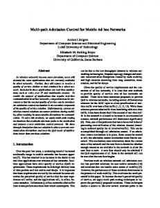
5 A Microcellular Example Manhattan-like microcellular environment This is a typical metropolitan environment consisting of building blocks of a square shape, Figure 1. Streets are running between the building blocks in two directions, horizontal and 14
vertical. In our simulation we assume that each block is of length 100 m. We further assume that radio-waves can propagate only along the streets. The link gain, gij , is modeled as a product of two variables, gij = lij � sij . The variable lij is the large scale propagation loss, which depends on the transmitter and receiver locations (see below). The variable sij is the variation in the received signal due to shadow fading. We assume that the variables sij 's are independent, and log-normally distributed with a mean of 0 dB , and a log-variance of � = 4 dB (which is typical for metropolitan areas, [7]). Each cell size is assumed to be half a block in all directions, and has one base station in one of the corresponding street corners, at lamp-post level. We take 77 (7 � 11) cells, and assume that base stations use omnidirectional antennas. We use a xed channel assignment scheme that divides the cells into Nc = 3 di�erent channel groups. The maximum transmitter power is set to 1W , and the receiver noise is taken to be 10?15 W . To model the large scale propagation loss denote by x and y the horizontal and the vertical distances, respectively, between the mobile and the base station. From [6], the large scale propagation loss between mobile i and base station j can be modeled by 2 � 20 � !(m?2) 13?1 !2 0 v u � � 2 2 (2 n ? 4) 2 2 u CA75 ; + x + 2y + x + y + 10 B lij = 6416 �cf2 xye? @1 + t xL+ y L Wx Wy xy
n
m
where c is the speed of light, f is the transmission frequency, and Wx and Wy are the street widths in the horizontal and vertical direction, respectively. The parameters n, Ln, m and Lm are all propagation constants, [7]. In our simulation we use f = 900 MHz, Wx = Wy = 25 m, n = 4, m = 25, Ln = 200 m and Lm = 700 m.
Method of comparison We will numerically evaluate the probabilities for type I and type II errors under the MIMIT and MD-MIT algorithms. We will also evaluate the expected number of DCPC phases required by the SAS algorithm, and the probability for an error of type II under the F-SAS algorithm. The two error probabilities can now be expressed by P(Error type I) = P(To admit the new mobile j H0 ), and P(Error type II) = P(To reject the new mobile j H1 ), 15
where H1 = fThe new mobile can safely be admittedg, and H0 = fThe new mobile cannot safely be admittedg. Type I error will result in an outage and may cause the dropping of an active call. Type II error will result in an erroneous blocking of the new mobile. From the user perspective, a type I error is more severe than a type II error. The errors are evaluated by the following simulation. We agree that the mobile in the centered cell in our 77 cell plan is always mobile 0 (which seeks for admission). This does not introduce any bias, as locations and link gains are randomly generated irrespective of the cell. Under any algorithm we sample a signi cantly large number of independent mobile locations and shadow fading (one mobile per cell). For every instance, we rst initialize the system with the state where all active mobiles are supported and use the stationary power vector. Then we record which one of the events H0, or H1, is in e�ect. The initialization is carried out by applying to mobiles f1; 2; : : : ; N g, the DCPC algorithm and a mobile removal algorithm from [3]. The removal algorithm results in a close to minimum number of mobile removals. To determine whether event H0 or H1 is in e�ect, we apply the DCPC algorithm again, but to the combined set of the supported mobiles and mobile 0. If all stationary powers are below the maximum level, then event H1 is in e�ect. Otherwise, H0 is in e�ect. After initialization, we execute the mobile admission algorithm with 10; 000 independent instances of event H0 , and 10; 000 of event H1. Type I error probability is estimated by counting the proportion of instances in the H0 events, where the algorithm admits mobile 0. Respectively, for type II error probability. Note that we "freeze" the mobiles after each sampling. This is a reasonable model when power control, removal and admission decisions are relatively much faster than mobile movements. Further, taking 10; 000 independent realizations of each event type results in small estimation errors. The power control update is stopped when the maximum relative di�erence between two consecutive power vectors ?p (t)j < 10?8 for every i. becomes smaller than 10?8 . That is, when jp (t+1) p (t) i
i
i
Numerical results The error probabilities under the MI-MIT algorithm are depicted in Figures 2 and 3. For each admission interference threshold, the error probabilities are presented as a function of the CIR target t (which is the same for all links). Clearly, the admission rule is relaxed by 16
increasing the thresholds. Therefore, we observe that the type I error probability increases with the threshold, and the type II error probability decreases. Since type I error is more severe than type II, it is common to select an admission threshold which keeps the probability for type I errors below some level, say 0:03. From Figure 2, this requires a threshold of 3 dB above the noise value (?150 dB ) for a CIR target in the range [13; 21 dB ); and a threshold of 6 dB above the noise value for a CIR target in the range [21; 30 dB ]. These thresholds result in type II error probabilities ranging from 0:43 to 0:99 for CIR targets in [13; 21 dB ), and around 0:7 for CIR targets in [21; 30 dB ). That is, to protect the active mobiles, MI-MIT will most likely reject the new mobile even when it could be accepted. These type II error probabilities are very high, and impractical. The error probabilities for di�erent CIR targets and thresholds under the MD-MIT algorithm, are depicted in Figures 4 and 5. The observations here are similar to those made for the MI-MIT algorithm. To keep type I error probability below 0:03, a CIR threshold of 50 dB above the CIR target must be taken, when the CIR target is larger than 24 dB . A higher threshold is required for lower CIR targets. As a result, type II error probabilities exceed 0:68. Again, this is obviously impractical. From the observation above it appears that N-IAC algorithms are impractical, if a CIR target must be maintained. Therefore, type I and type II error free algorithms as SAS, could resolve the problem. However, there is a severe concern on its convergence rate. We evaluate it by running 10; 000 independent instances of SAS under each event (H0 and H1) until convergence, and counting the number of DCPC phases. It turned out that for any CIR target, SAS admits the new mobile in the rst DCPC phase, for almost all instances of type H1 (can safely be admitted). However, for any instance of type H0 , SAS requires more than one DCPC phase to reject the new mobile. Actually, it requires quite a lot of phases to do so. The mean number of DCPC phases required by SAS to reject a new mobile (under H0 events), is depicted in Figure 6. The extremely fast (slow) convergence under events of type H1 (H0) is discussed in Remark 4.2, and is due to typically low (high) cochannel interference under such events. This asymmetric behavior puts the spot light on Fast-SAS, which executes only one DCPC phase. Since it makes no errors of type I, its practicality mainly depends on its type II errors. The probability for that are evaluated by taking 40; 000 instances of type H1 events. The 17
results are shown in Figure 7. Observe that these probabilities are less than 3% for all CIR targets.
6 Conclusions We close with the following conclusions. Our case study reveals that N-IAC algorithms are problematic. Apparently, the interference and CIR levels at a mobile arrival, bear no su�cient information for a good admission decision. A relatively small interference level does not indicate that the new mobile can safely be admitted, and vice versa. Therefore IAC algorithms must be examined. The SAS algorithm, which is an IAC algorithm, and type I and type II error free, is extremely fast to admit a new mobile, but extremely slow to reject it. Thus, it seems that the most costly part is to lower the probability of type II errors. The Fast-SAS algorithm, which is type I error free, but makes type II errors, saves the costly part above. It turns out that it can sustain an acceptable level of type II errors under any CIR target. Further, it only requires a simple modi cation in the DCPC scheme, and takes a decision when DCPC converges.
APPENDIX Proof of Lemma 4.1: From the Lemma assumptions we have,
p = p(1 + �) � t (Ap + �)(1 + �) = t (Ap(1 + �) + � + ��) � t (Ap + � + �) : 2
Proof of Lemma 4.2: Let vector p(0) = p�(�)(1 + �) be the initial powers used by the
DCPC algorithm with noise vector (� + �), as de ned in (2). From Lemma 4.1, and this Lemma assumptions, we have for k = 0
p(k) � minfP ; t (Ap(k) + � + �)g = t (Ap(k) + � + �) :
(11)
From [11, Lemmas 6 and 9], it follows that the sequence of the power vectors, fp(k)g, resulting from the DCPC algorithm initialized by p(0) (which satis es the super-harmonic function condition (11)), has the following properties. 18
It is a non-increasing sequence, Eq. (11) holds for every k, and it converges to p�(� + �). Thus, every power vector p(k) supports all mobiles, and p�(� + �) � p(0) = p�(�)(1 + �) .
2
Proof of Lemma 4.3: Since all mobiles are supported under both noise vectors, we have from (4),
p�(�0) = t (Ap�(�0) + �0) > t (Ap�(�0) + �) :
(12)
Let p�(�0) be the initial power vector for the DCPC algorithm for noise conditions �. From [11, Lemmas 6 and 9], it follows from (12), that the resulting power sequence is non-decreasing and converges to p�(�). Moreover, the rst power vector in the sequence equals to the right-hand side of (12). (This is also a well known result for sub-harmonic functions with respect to any operator.) Thus, (12) implies p�(�0) > p�(�).
2
Proof of Lemma 4.4: If there is a xed point solution to (6) subject to (8), then it clearly satis es the constraints in De nition 4.1.
If the xed point solution in De nition 4.1 has p0 > x�, then it will contradict the de nition of x�. Indeed, it will imply that x� is not the maximum.
2
Proof of Theorem 4.1: Note that SAS admission algorithm may stop at phase k under two conditions. One condition is when at step 2, �k = 0 for the rst time; or the power limit in the previous phase, p�0(k ? 1) > p�0, and mobile 0 has not been accepted. In these cases, mobile 0 is rejected. The other condition is at step 4.1 when 0�(k) = 0t and p�0(k) � p�0 , for the rst time. In this case, mobile 0 is accepted.
First we prove that SAS is soft, i.e., the CIR corresponding to each transmitter i ; 1 � i � N , does not drop below its target it, at any moment during the algorithm execution. We split this part of the proof into two cases. Case (i) is until SAS stops, and case (ii) is after it stops (and DCPC continues). 19
Consider case (i). From Observations 1 and 2, and Lemma 4.2, it is su�cient to show that for every phase k before SAS stops,
�i0(k) def = ai;0(�p0(k) ? p�0(k ? 1)) � �k (�i + ai;0 � p�0(k ? 1)) ; 8 1 � i � N ; and
pi (0; k) def = p�i (k ? 1)(1 + �k ) � p�i ; 8 1 � i � N : Note that �0(k) is the additional noise added at the beginning of phase k, on top of the noise at phase k ? 1 (which also include the new mobile transmitting power). These two inequalities are readily veri ed from the updates at step 2 of the SAS algorithm. Thus, SAS is safe until it stops. Consider case (ii). Assume SAS stops by rejecting mobile 0 at step k. Then the system is at a power vector (p�1(k ? 1); : : : ; p�N (k ? 1)) used for mobiles f1; 2; : : : ; N g. Since this vector satis es the super harmonic function conditions in (11), it follows as in the proof of Lemma 4.2, that mobiles f1; 2; : : : ; N g will be supported later on. Assume that SAS stops by accepting mobile 0 at step k. Then from step 4.1 of the SAS algorithm, and the fact that mobiles f1; 2; : : : ; N g were supported during phase k, we have
i�(k) = it for every 0 � i � N . That is, (p�0(k); p�1(k); : : :p�N (k)) is the stationary power vector supporting mobiles f0; 1; : : : ; N g. Next we prove that SAS algorithm is also safe. Assume that mobile 0 can safely be accepted. We will show that it will be accepted by the SAS algorithm. From the de nition of x� and the updates in step 2 of SAS, �k > 0 as long as p�0 (k ? 1) < minfx�; p�0g. Thus, mobile 0 is not rejected as long as p�0(k ? 1) < minfx�; p�0 g. From Observation 1 above, fp�0(k)g is strictly increasing as long as p�0(k ? 1) < minfx�; p�0 g. Thus, from Lemma 4.4, mobile 0 will eventually be admitted. Assume now that mobile 0 cannot be safely accepted. Then from Lemma 4.4, there is no solution to (6) subject to (8). Thus, for no phase k, the admission conditions at step 4.1 of the SAS algorithm are satis ed, as long as p�0(k) � minfx�; p�0 g. That is, mobile 0 is not accepted as long as p�0(k) � minfx�; p�0g. From Observation 1 above, fp�0(k)g is strictly increasing as long as p�0 (k) < minfx�; p�0g. From the de nition of x� and �k , �k will eventually become zero, or p�0 (k ? 1) will eventually exceed p�0, in which case mobile 0 will be rejected. 2 20
References [1] J. M. Aein. Power Balancing in Systems Employing Frequency Reuse. Comsat Tech. Rev., Vol. 3, No. 2, 1973. [2] M. Almgren, H. Andersson and K. Wallstedt. Power Control in a Cellular System. Proc. IEEE Veh. Tech. Conf., VTC-94:833{837, 1994. [3] M. Andersin, Z. Rosberg and J. Zander. Gradual Removals in Cellular PCS with Constrained Power Control and Noise. IEEE/ACM Wireless Networks, Vol. 2, pp. 27{43, 1996. [4] N. Bambos and G. J. Pottie. On Power Control in High Capacity Cellular Radio Networks. Proc. 3rd WINLAB Workshop, Oct. 19-20, 1992. [5] N. Bambos, S. C. Chen and G. J. Pottie. Channel Access Algorithms with Active Link Protection for Wireless Communication Networks with Power Control. Technical Report, UCLA-ENG-95-114, Department of Electrical Engineering, UCLA, 1995 (submitted to IEEE/ACM Tran. in Networking). [6] J-E. Berg. A Simpli ed Street Width Dependent Microcell Path Loss Model. COST 231, TD(94)035, 1994. [7] J-E. Berg, R. Bownds and F. Lotse. Path Loss and Fading Models for Microcells at 900 MHz. Proc. IEEE Veh. Tech. Conf., VTC-92:666{671, 1994. [8] G. J. Foschini. A Simple Distributed Autonomous Power Control Algorithm and its Convergence. IEEE Trans. on Veh. Tech., Vol. 42, No. 4, 1993. [9] S. A. Grandhi, R. Vijayan and D. J. Goodman. A Distributed Algorithm for Power Control in Cellular Radio Systems. 13th Annual Allerton Conf. on Commun., Contr. and Computing, Monticello, Illinois, Sept. 1992. [10] S. A. Grandhi, R. Vijayan, D. J. Goodman and J. Zander. Centralized Power Control in Cellular Radio Systems. IEEE Trans. on Veh. Tech., Vol. 42, No. 4, 1993. [11] S. A. Grandhi, J. Zander and R. Yates. Constrained Power Control. Wireless Personal Communications, Vol. 1, No. 4, 1995. [12] M. Gudmundson. Cell Planning in Manhattan Environments Proc. IEEE Veh. Tech. Conf., VTC-92:435{438, 1992. [13] J. C. Lin, T. H. Lee and Y. T. Su. Power Control Algorithm for Cellular Radio Systems. Electronics Letters, Vol.30, No. 3, 195{197, 1994. [14] H. J. Meyerho�. Methods for Computing the Optimum Power Balance in Multibeam Satellite. Comsat Tech. Rev., Vol. 4, No. 1, 1974. [15] D. Mitra. An Asynchronous Distributed Algorithm for Power Control in Cellular Radio Systems. Proc. 4th WINLAB Workshop, Oct. 19-20, 1993. 21
[16] R. W. Nettleton and H. Alavi. Power Control for Spread-spectrum Cellular Mobile Radio System. Proc. IEEE Veh. Tech. Conf., VTC-83:242{246, 1983. [17] J. Zander. Performance of Optimum Transmitter Power Control in Cellular Radio Systems. IEEE Trans. on Veh. Tech., Vol. 41, No. 1, 1992. [18] J. Zander. Distributed Cochannel Interference Control in Cellular Radio Systems. IEEE Trans. on Veh. Tech., Vol. 41, No. 3, 1992.
22
Wy y
x Wx Figure 1: The asymmetric AHS(1,1) cell plan with cluster size Nc = 3. The dark crosses are the cochannel cells and the white squares are the buildings seen from above.
23
Admission threshold = −150 dB + ∆ 1
∆ = 16 dB
0.9
P(Error type I)
∆ = 13 dB 0.8
∆ = 10 dB
0.7
∆ = 6 dB ∆ = 3 dB
0.6 0.5 0.4 0.3 0.2 0.1 0 8
10
12
14
16
18
20
22
24
26
28
Target CIR [dB]
Figure 2: The probability of type I error as a function of the target CIR for the MI-MIT admission control algorithm with di�erent values of the interference admission threshold. 7 � 11 cochannel cells. Noise value = 10?15 W (?150dBW ).
24
Admission threshold = −150 dB + ∆ 1
∆ = 3 dB
0.9
P(Error type II)
∆ = 6 dB 0.8
∆ = 10 dB
0.7
∆ = 13 dB ∆ = 16 dB
0.6 0.5 0.4 0.3 0.2 0.1 0 8
10
12
14
16
18
20
22
24
26
28
Target CIR [dB]
Figure 3: The probability of type II error as function of the target CIR for the MI-MIT admission control algorithm with di�erent values of the interference admission threshold. 7 � 11 cochannel cells. Noise value = 10?15 W (?150dBW ).
25
Admission threshold = Target CIR + ∆ 1 0.9 0.8
P(Error type I)
0.7 0.6 0.5 0.4
∆ = 30 dB ∆ = 35 dB
0.3
∆ = 40 dB
0.2
∆ = 45 dB ∆ = 50 dB
0.1 0 8
10
12
14
16
18
20
22
24
26
28
Target CIR [dB]
Figure 4: The probability of type I error as a function of the target CIR for the MD-MIT admission control algorithm with di�erent values of the CIR admission threshold. 7 � 11 cochannel cells. Noise value = 10?15W (?150 dBW ).
26
Admission threshold = Target CIR + ∆ 0.8
∆ = 50 dB
0.7
∆ = 45 dB
P(Error type II)
0.6
∆ = 40 dB ∆ = 35 dB
0.5
∆ = 30 dB 0.4
0.3
0.2
0.1
0 8
10
12
14
16
18
20
22
24
26
28
Target CIR [dB]
Figure 5: The probability of type II error as a function of the target CIR for the MD-MIT admission control algorithm with di�erent values of the CIR admission threshold. 7 � 11 cochannel cells. Noise value = 10?15W (?150 dBW ).
27
Nr. of DCPC phases required to reach to the decision REJECT 800
Mean number of DCPC phases
700
600
500
400
300
200
100
0 5
10
15
20
25
30
Target CIR [dB]
Figure 6: The mean number of DCPC phases that is required for the SAS algorithm to reach to a decision when the new mobile should be rejected (event of type H0).
28
F−SAS
−1
10
P(Error type II) = 3%
−2
P(Error type II)
10
−3
10
−4
10
−5
10
10
12
14
16
18
20
22
24
26
28
30
Target CIR [dB]
Figure 7: The probability of type II error as a function of the target CIR for the F-SAS admission control algorithm. The number of instances of type H1 is in this case 40000. The probability of error is not larger than 3% for all target CIRs. 7 � 11 cochannel cells. Noise value = 10?15 W (?150 dBW ).
29