Soft Errors in SRAM-FPGAs: a Comparison of Two Complementary Approaches Monica Alderighi, Member IEEE, Fabio Casini, Member IEEE, Sergio D’Angelo, Marcello Mancini, Sandro Pastore, Luca Sterpone, Member IEEE, and Massimo Violante, Member IEEE Abstract— As SRAM-based FPGAs are introduced in safetyor mission-critical applications, the availability of suitable Electronic Design Automations (EDA) tools for predicting systems dependability becomes mandatory for designers. Nowadays designers can opt either for workload-independent EDA tools, which provide information about system’s dependability disregarding the workload the system is supposed to elaborate when deployed in the mission, or workloaddependant approaches. In this paper, we compare two tools for predicting the effects of soft errors in circuits implemented using SRAM-based FPGAs, a workload-independent one (STAR) and a workload-dependant one (FLIPPER). Experimental results show that the two tools are complementary and can be used fruitfully for obtaining accurate predictions. Index Terms— Dependability, Field Programmable Gate Arrays (FPGA), Single Event Effects, Fault Injection, Triple Modular Redundancy (TMR).
W
I. INTRODUCTION
hen developing high reliability applications using SRAM-based Field Programmable Gate Arrays (FPGA), designers have to devote a significant amount of time in analyzing whether and how soft errors may corrupt the system’s expected functionalities. Devices are normally characterized using the well-known cross section figure, which can be seen as the probability for a particle to originate an upset in the device. As a matter of fact, this figure is not sufficient to characterize the application implemented in the device. Besides the device’s cross section, several factors have to be considered in order to compute the application’s error cross section [1]. This can be seen as the probability for a particle to produce an application failure, i.e., the particle interacts with the device producing a soft error that affects the task Manuscript received September 7, 2007. The work is supported by the European Space Agency under contract 18559/04/LvH/gm. M. Alderighi (corresponding author), and S. D’Angelo are with the Istituto Nazionale di Astrofisica, Istituto di Astrofisica Spaziale e Fisica Cosmica, 20133 Milano, Italy (phone +39 02 23699332, fax: +39 02 2362946, e-mail:
[email protected],
[email protected]). F. Casini, M. Mancini, and S. Pastore are with the Sanitas EG s.r.l., 20135 Milano, Italy (e-mail:
[email protected],
[email protected],
[email protected]). L. Sterpone and M. Violante are with the Politecnico di Torino, Dipartimento Automatica e Informatica, 10129 Torino, Italy (e-mail:
[email protected],
[email protected]).
978-1-4244-1704-9/07/$25.00 ©2007 IEEE
performed by the application, leading eventually to the computation of wrong results. The adoption in the application of hardening solutions like for example the triple modular redundancy [2], as well as the workload (i.e., the input stimuli being applied to the application’s inputs) must also be considered when quantifying the application’s error cross section. The application’s error cross section can be obtained resorting to many different techniques. Accelerated groundbased radiation testing can be exploited for this purpose [3], but the execution of such experiments can be quite time and resource demanding. In order to reduce the costs related to radiation testing, designers can benefit from alternative techniques aimed at mimicking the interaction between radiations and devices, like laser-based or emulation based fault injection [4][2]. The rationale behind the adoption of techniques besides radiation testing is to exploit them during design, while resorting to radiation testing only to perform the final validation of the obtained system. No matter the method used to insert faults in the system, the aforementioned approaches can all be referred to as workload-dependant, as they all require for the system under analysis to be stimulated using a set of input stimuli (i.e., the workload). As far as applications implemented using FPGAs are concerned, a further set of techniques can be exploited, which are based on analyzing the topology of the circuit, and allow predicting its sensitivity to soft errors without resorting to neither injection of faults or simulation of the applications [5]. This latter class of techniques can be referred to as workloadindependent. The purpose of this paper is to analyze two of such techniques in order to evaluate on a case study their peculiarities, and to understand if they can complement each others as to obtain an effective analysis tool, which provides greater accuracy and higher efficiency than what possible when adopting only one of these techniques. Our investigations targeted a data handling circuit hardened against Single Event Upsets (SEUs) according to the X-TMR technique [6], which we implemented using a Xilinx’s XQR2V6000 device. For the sake of this paper, we focused on predicting the effects of SEUs originated by ionizing radiations in the
device’s configuration memory. For this purpose, in our investigations we considered FLIPPER [7], a fault injection tool developed to analyze the SEU impact in applications implemented using SRAM FPGAs as example of workloaddependent approaches, and STAR [5] an analyzer tool able to predict the error cross section of circuits implemented using SRAM-FPGAs without the need for running neither fault injection nor simulations as example of workload-independent approaches. The analysis shows that there is agreement between the experimental results from the two different approaches for the considered circuit. Generally speaking, STAR is effective in catching any X-TMR violations in an implemented circuit, while FLIPPER is able to analyze how SEUs affect any implemented design, in dependence of a given workload. STAR produces a worst case estimation of the application’s error rate, since it performs a static analysis of the circuit and does not take into account the dependency of the error cross section on the workload. FLIPPER produces an estimate of the application’s error rate on the basis of the defined workload, since the implemented circuit is exercised during fault injection. The differences between the two approaches suggest that the results have to be correlated with care. Nevertheless, the independence of the approaches, together with the agreement of results, plays a favorable role in their validation, which needs radiation ground testing to be completed. The rest of the paper is organized as follows. In Section II related and previous works are reported, while an overview of the FLIPPER and STAR tools is given in Section III. The procedure followed for the evaluation is sketched in Section IV. The experimental results and analysis are discussed in Section V. Finally conclusions are drawn in section VI.
II. RELATED WORK Various systems have been reported in the literature for dependability evaluation in VLSI circuits for hi rel/space applications. Such systems check the response of a circuit in presence of faults by comparing the behavior of the fault free circuit and the faulty one for a given set of stimuli or test patterns, we can thus refer to them as workload-dependant approaches. Besides radiation testing in e.g. particle accelerator facilities, SEU injection can also be performed by simulation [8][9][10]. Both methods are relatively slow due to either a limited upset rate, or a reduced device operation speed respectively. FPGA emulation based fault injection has proven effective to reduce fault evaluation time in this context, because it allows a high upset rate as well as a high speed operation of the design under test. FPGA fault injection can be used to evaluate the SEU sensitivity of an ASIC design, injection is then performed in flip-flops or memories of the target design only, by either reconfiguring the device in order to present the
faulty behavior [11][12] or modifying the original circuit adding extra hardware to modify the state of the circuit [13][14]. These approaches do not consider the FPGA as the target technology. In case SRAM-FPGA themselves are employed in avionic or space applications, SEU injection must be done also in the device configuration memory and not in flip-flops only. As the configuration memory is not modeled in the netlist of the target design, logic simulation can not be used. But SEU fault injection by partial reconfiguration can be exploited to evaluate the degree of protection of mitigation techniques, or to get a rough evaluation of circuit behaviors prior to radiation testing. A configuration bitstream SEU emulator for SRAMFPGA was described in [15]. The goal of the simulator was to provide a map of the sensitive bits of the device configuration memory. A prototypal system aimed at studying the SEU sensitivity of the reconfiguration logic of Xilinx Virtex devices was described in [16]. A similar system was used for radiation test activity for the same devices reported in [17]. Analytical approaches also exist based on software programs. In [18] a static estimation of the mapped circuit’s sensitivity to SEUs is presented assuming that all the memory bits are susceptible. Consequently, an approach that identifies the path sensitive to SEUs and calculates the probability error rate is proposed in [19]. These approaches are very pessimistic and able to provide only probabilistic estimation of SEU effects.
III. TOOL DESCRIPTION A. STAR Overwiew STAR is a new technique predicting the possible impact of SEUs in SRAM-based FPGA systems without resorting to simulation neither fault injection, which can be referred to as workload-independent approach [5]. The technique is based on a topological inspection of the design implemented using SRAM-based FPGAs. By coupling information about the modification SEUs may induce in the resources of the used FPGA device with a set of dependability rules, the technique is able to identify all the possible SEUs which modify the circuit topology in such a way that, when a suitable stimuli is applied over the circuit’s inputs, the circuit produces erroneous results. The technique is pessimistic in the sense that it identifies all the possible source of errors, independently of the workload the circuit is supposed to process. In the case an SEU requires a peculiar input stimuli for being observed that is not included in the circuit’s workload, it will never lead the circuit to produce an error when deployed in its mission. The idea behind STAR is to identify a set of rules, dependability rules in the following, which must be enforced by a circuit in order to be resilient to soft errors. As the modifications to an FPGA configuration following the occurrence of a soft error are finite, and known, STAR is able to first derive the modified circuit starting from the
original one, and to verify whether the modified circuit complies or not with the dependability rules. In case violations are found, STAR reports the information about the soft error responsible for the violations (for example, it reports the address of the bit within the device’s configuration memory that when altered by a soft error corrupts the adopted mitigation technique). Fig. 1 depicts the architecture of STAR, and shows the following elements: Static Analyzer: it is the tool that checks whether the placed and routed circuit is sensitive to soft errors affecting either the memory elements the designers embedded in the circuit, as well as the configuration memory of the SRAM-based FPGA implementing the circuit. Circuit Description: it is a file containing the structural description of the circuit, which consists of logic functions (either combinational or sequential) and connections between them. Both the logic functions and the connections between them are described in terms of FPGA’s resources. Layout Description: it is a file containing the description of where each resource in the Circuit Description is placed and routed on the FPGA area. Dependability Rules: it is a database of constraints that must be fulfilled by the placed and routed circuit in order to be resilient to the effects provoked by SEUs. More details about the Dependability Rules are reported in [20]. Report of Violations: it is a file that lists all the violations of the Dependability Rules that the Static Analyzer identified. Each entry of the file describes the memory element, and the FPGA’s resource responsible for the violation.
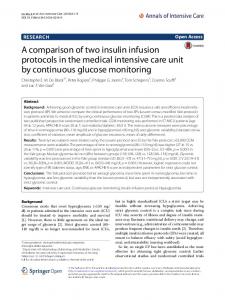
B. FLIPPER Overview FLIPPER * is a tool (whose development was funded by ESA [7]) aimed at evaluating Single Event Upset (SEU) and Multiple Bit Upset (MBU) effects in Xilinx SRAM-based FPGAs. Upsets are emulated by fault injection into the configuration memory. An earlier prototype of an SEU emulator by fault injection for SRAM-FPGAs was published in [21][16]. FLIPPER can be used to evaluate the SEU sensitivity of a design, for example, by collecting a probability distribution of the number of randomly injected faults in configuration memory necessary to cause a functional fault. This information can be also useful for defining the scrubbing rate of the configuration memory [22]. In another way, FLIPPER can be used to probe the configuration memory’s sensitive bits of implemented designs, by systematically upsetting each memory bit. The system comprises three main parts: A flexible FPGA-based board (Control Board) that rules the fault injection procedure A Device Under Test (DUT) Board that contains the FPGA to be tested, an XQ2VR6000 device A Personal Computer. A picture of FLIPPER showing the Control Board and the DUT board stacked on it is shown in Fig. 2.
Dependability Rules Circuit Description
Fig. 2. FLIPPER Control Board and superimposed DUT Board. Static Analyzer Layout Description Report of Violations
Fig. 1. The proposed approach. The Figure reports the developed Static Analyzer tool, the input information and the output results.
Given the Circuit and Layout Descriptions, the Static Analyzer verifies whether all the constraints described in the Dependability Rules are fulfilled. In case any violation is found an entry is stored in the Report of Violations file.
SEUs are injected by bitstream manipulation. Both single and multiple upsets can be injected. In case of an MBU, two adjacent bits in a frame are modified at one time. One single injection at a time is performed, after which the DUT is exercised at nominal speed for the whole set of test vectors. The stimuli are imported from simulation waveforms. The location in the bitstream of an injected upset can be random, sequential, or user defined. Sequential mode means that every bit of the bitstream addressing the configuration memory is accessed and modified in sequential order. In random mode, SEUs are accumulated until the first output error is observed. In user-defined mode, selected locations for injection are provided via a text file. FLIPPER reports all *
Patent pending
discrepancies for the expected behavior by a real time comparison of design outputs and gold vectors. Test results are collected in a text file, which can also be used to produce the distribution of probability to the first output error. For the circuit being investigated in the paper, the user defined and sequential injection strategies have been employed. As far as the sequential strategy is concerned, the flow diagram is illustrated in Fig. 2. Indeed, the user defined strategy performs as the sequential one, while acting on a subset of memory locations. The XQR2V6000 is initially configured with the circuit design. In order to check whether or not the device has been properly configured, a functional test is performed. If the check fails, the test ends; otherwise the test proceeds with the injection into the configuration memory and the successive functional test. After each injection the modified bit is restored. If all target locations of the configuration memory have been analyzed, the test ends. START
EXIT TEST1
The output of the 6x6 multiplier consists of 1-bit data output for each replica, representing the parity of multiplication result. The device resource usage for the above circuits when implemented in a Xilinx XQR2V6000 FPGA is illustrated in Table I, where for each X-TMR circuit the number of used Control Logic Blocks (CLBs), Input/Output Blocks (IOBs), Slices and Look-Up Tables (LUTs) and Flip-Flops (FFs) are reported. Concerning X-TMR, the entire circuits, the input signals (including power and ground), and output signals have been triplicate. For the outputs the triple voted scheme has been adopted. Table I CHARACTERISTICS OF THE IMPLEMENTED CIRCUITS
Device Configuration
NO
Results from both tools are finally compared and correlated. We have selected three benchmark applications: COUNT8: a counter with programmable step, working on 8-bit data input and 20-bit data output FIR: a FIR filter with 64 stages and working with 8-bit data input and output MULT6: a 6x6 bit multiplier, instanced by 100 replicas.
Resources CLB [#] IOBs [#] Slices [#] LUTs [#] FFs [#]
Functional test passed? YES Corrupt the bit
COUNT8 33 90 130 144 120
FIR 401 48 1,603 165 1,548
MULT6 2,742 345 10,970 15,033 3,600
The execution of the selected benchmark applications has been performed applying a sequence of input stimuli, starting from the all-zero input pattern, and increasing the pattern by one at each clock cycle.
Functional Test
Fix the bit
V. EXPERIMENTAL RESULTS AND ANALYSIS Injection over?
NO
YES
END 1A
malfunction has occurred, and the test cannot proceed.
Fig. 3. Sequential injection flow diagram.
IV. EXPERIMENTAL PROCEDURE This section describes the procedures that have been followed to compare FLIPPER and STAR approaches . We have started by producing hardened versions of selected designs according to the X-TMR technique [23][24]. These have then been analyzed by FLIPPER and STAR in order to identify possible critical bits, that is those bits that when altered by an SEU affect more than one redundant domain.
We have performed three different experimental campaigns in order to compare FLIPPER and STAR approaches. The purpose of these campaigns is focused on a detailed analysis of the results produced by FLIPPER and STAR respectively. The analysis we have provided includes a characterization of the identified criticalities induced by a single bit-flip, reporting the involved resources (i.e. logic or interconnection resources) as well as the circuit signal or module interested in the failure. A. COUNT8 A first experimental campaign has been performed considering the Counter benchmark application. In this case the STAR tool has been run first to generate the list of Violations according to the Dependability rules defined in [5]. Then a user-defined fault injection has been performed by FLIPPER, addressing memory bit locations revealed as
critical by the STAR analysis. The results show four bits identified as critical by STAR; among these, three bits have been identified as critical also by FLIPPER. The detailed results of this analysis are reported in the table II, where the first column indicates the linear address of the configuration bit in the bitstream, the second/third column indicates whether or not the bit was detected by STAR/FLIPPER, the fourth column indicates the involved resource, the fifth column indicates the resource coordinates, and finally the sixth column indicates the fault type. The first critical effect has been observed on an interconnection resource of the Switch Matrix (SM) In detail, this bit provokes a short effect between two interconnection points (OMUX14 and XQ0 Programmable Interconnection Points or PIPs), belonging to two feedback voter signals of different TMR domains. This effect has been observed by STAR since it does not satisfy the reliability rules the tool checks. In this case FLIPPER does not report any error on the circuits output, since the induced effect is masked by the adopted workload. The other observed critical effects are related to the logic resources embedded within a Configurable Logic Block (CLB). In detail, the resources affected include the first bit of a Look Up Table (LUT), a bit controlling the MUX Y component and a bit controlling the MUX OUT component. Each of these critical bits, due to the topology of the circuit signal, generates a common mode failure, affecting an internal power signal of the circuit that is generated by a LUT in the CLB at the coordinates R[17]C[61]. The power signal is then propagated to all the three domains of the TMR structure. Thus, a single modification of one of these resources generates a multiple failure in the TMR structure. This condition is demonstrated by the FLIPPER analysis that reports error in all the three cases. The considered resources are illustrated in Fig. 4.
The results of this analysis are summarized in Table III. The nomenclature is the same as the previous experiment. The analysis performed by STAR identifies four critical bits: one within an SM, one within the content of a LUT, and two within MUX resources inside a CLB. The same effects observed in the Counter circuit, is observed also in this case. The bit affecting the LUT modifies the logic function performed and the two bits affecting the MUXes change the control signal of the resource, while the bit affecting the routing resources provokes a short effect between two interconnection points (PIP S2BEG2 and Y1), that are belonging to two feedback voter signals of different TMR domains. This situation is reported in Fig. 5, where it is illustrated that the routing segment S2BEG2 Y1 gets active, because of the bit-flip. The two involved signals are related to the FIR stage computation of two different TMR domains, thus it does not satisfy the STAR reliability rules.
Fig. 5. Graphical representation by the FPGA Editor of the short between two nets of the FIR Filter circuit. The short is identified by a white interconnection segment circled by the oval.
Fig. 4. The logical resources involved by the three critical bits in Table II affecting the same logical nets, as derived by the STAR analysis. The components LUT, MUX Y, MUX OUT are identified by the ovals.
B. FIR Filter The second experimental campaign aims at evaluating a FIR Filter circuit. In this case FLIPPER and STAR have been run in parallel, using a sequential mode injection for the former. Faults have been injected into the entire device configuration memory, for a total of 21 106 injections.
The analysis performed by FLIPPER reveals four configuration memory bits that provoke errors in the circuit outputs. In particular three of these bits are also identified by STAR as critical; the fourth bit detected by FLIPPER is located in the Input Output interconnection block. The actual version of STAR does not allow to determine whether or not a bit is critical when the Input/Output blocks are considered. However, it is able to analyze a selected bit reporting the induced modifications. In detail, the bit in question, numbered 110,854, is in an Input Output Interconnection (IOI) block located in the block LIOIR96. This situation is illustrated in Fig. 6. We have exploited STAR in order to identify the induced critical effect. STAR reported a short between the E2END8 and IOIS_FAN_BX1 PIPs. Further analysis on the signal topology of the multiplier
circuit allows us to identify the affected interconnections. The involved signals are related to the internal ground signal of the TMR domain 2 and the parity checker of the TMR domain 1; this short provokes a multiple error that is propagated to the TMR architecture.
Fig. 6. Graphical representation by the FPGA Editor of the short between two nets of the FIR Filter circuit within an Input Output interconnection block. The short is identified by a white interconnection segment circled by the oval.
The bit identified by STAR as critical, while identified as not critical by FLIPPER, affects the SM and corresponds to an upset whose effect is masked by the adopted workload. C. MULT6 We have performed a last experimental campaign analyzing a Multiplier circuit. The analysis performed using STAR does not identify any critical bit. However, FLIPPER founds three bits, as reported in Table IV. For the first bit, the condition is similar to the one detected for the FIR Filter circuit above, that is a bit-flip provoking an unwanted short. As far as the last two bits are concerned, these have been found by FLIPPER as preventing the partial configuration of the device, causing a Busy error of the DUT. Nevertheless, further investigations are needed to fully diagnose these failures. D. Analysis Despite the fact the fact that the proposed approaches are completely different and the described tools were developed independently of each other, similar results have been obtained. The tool independency and result agreement constitute a first step towards mutual validation of the tools. To further confirm such a result, our analyses need to be extended to additional circuits. Concerning the reported critical failures, they are due to single bit-flip induced within the FPGA configuration memory, thus they demonstrate that standard TMR hardening approaches may fail in some particular cases when applied to SRAM-based FPGAs. In principle, STAR produces an upper bound to the number of critical configuration memory bits, since it is workload independent. In spite of that, the results show that there is one
bit that has not been identified as critical by STAR, while it has been detected by FLIPPER. This is due to the fact that the resource involved is not addressed by the actual release of the STAR tool. As far as FLIPPER is concerned, it is expected to miss some bits identified as critical by STAR, given its workload dependency. As shown by the results, in two of the presented circuits, there is one bit that has been masked by the workload, namely the one affecting the SM. What appears as a drawback, can be exploited to reduce the number of critical bits found by STAR, by taking into account the impact of the workload. Interestingly, the FLIPPER analysis reveals failures of the device programming ability, which directly impact the periodic scrubbing operation, and thus application reliability. Scrubbing is the well known SEU mitigation technique for SRAM based FPGAs, which consists of rewriting configuration bitstream at a certain rate.. If configuration fails, or the configuration logic is no longer able to accept commands, scrubbing has no effect in cleaning the configuration memory of possible bit-flips. Simulative approaches although highly optimized and supported by dedicated hardware, like FLIPPER, may fall short in providing results in a reduced amount of time. However, they are invaluable to assess the dependence of upset effects with the workload. To boost the performance of simulative approaches, a clever selection of where to inject faults is needed, and the output produced by STAR can be used for such purpose. From the point of view of the circuit analysis, STAR allows the accurate identification of the routing or logic failure induced by the injected bit-flips. To this purpose we have shown that STAR should be used to identify the routing signal or logic component involved, thus supporting the circuit debugging. The analysis we have performed on the TMR circuit allow us to identify particular configuration memory bit criticalities that the hardening technique adopted is not able to cope. We are investigating the adoption of reliability-oriented place and route [20] in order to completely protect circuits against multiple error.
VI. CONCLUSIONS In this paper we provided an accurate comparison of two complimentary approaches to analyze the SEUs sensitiveness of SRAM-based FPGAs. The experimental results, although preliminary, show the good agreement of the workload independent and workload dependant approaches investigated in the paper. STAR can be used as generator of the locations where to inject for FLIPPER and for the identification of the fault type, while FLIPPER can be used to assess how the workload affects the propagation of upset-induced circuit modification. From the scientific point of view, the presented work
describes in details the criticalities of X-TMR hardening techniques when adopted on Xilinx SRAM-based FPGAs. These critical effects need to be considered by space and avionics designers adopting Xilinx FPGAs in safety-critical
applications.
TABLE II COUNTER RESULTS
Bit Position
STAR
10,510,980 10,637,088 10,629,222 10,629,230
Yes Yes Yes Yes
FLIPPE R No Yes Yes Yes
Resource Type
CLB coordinates
Fault type
SM LUT MUX Y MUX OUT
R[15]C[60] R[17]C[61] R[17]C[61] R[17]C[61]
Short PIP OMUX14 ↔ XQ0 LUT first bit upset Control bit upset Control bit upset
TABLE III FIR FILTER RESULTS
Bit Position
STAR
110,854 14,047,967 13,582,456 13,574,590 13,574,598
N.A. Yes Yes Yes Yes
FLIPPE R Yes No Yes Yes Yes
Resource Type
CLB coordinates
Fault type
IOI SM LUT MUX Y MUX OUT
LIOIR96 R[63]C[16] R[32]C[78] R[32]C[78] R[32]C[78]
Short E2END8 ↔ IOIS_FAN_BX1 Short PIP S2BEG2 ↔ Y1 LUT first bit upset Control bit upset Control bit upset
TABLE IV MULTIPLIER RESULTS
Bit Position
STAR
110,854 323,380 409,973
N.A. N.A. N.A.
FLIPPE R Yes Yes Yes
Resource Type
CLB coordinates
Fault type
IOI IOI IOI
LIOIR96 BIOIC1 BIOIC1
Short E2END8 ↔ IOIS_FAN_BX1 Busy Error of the DUT Busy Error of the DUT
REFERENCES [1]
V. Asenek, C. Underwood, R. Velazco, S. Rezgui, M. Oldfield, Ph. Cheynet, R. Ecoffet, “SEU induced errors observed in microprocessor systems”, IEEE Trans. on Nuclear Science, Vol. 45, No. 6, 1998, pp. 2876-2883 [2] D.K. Pradhan, Fault-Tolerant Computer System Design, Prentice Hall [3] T.P. Ma, P.V. Dressendorfer, Ionizing Radiation Effects in MOS Devices and Circuits, Wiley-Interscience [4] F. Darracq, H. Lapuyade, N. Buard, F. Mounsi, B. Foucher, P. Fouillat, M. –C. Calvet, R. Dufayel, R., “Backside SEU laser testing for commercial off-the-shelf SRAMs”, IEEE. Trans. on Nuclear Science, 2002, Vol. 49, No. 6, Dec. 2002, pp. 2977-2983 [5] L. Sterpone, M. Violante, “A New Analytical Approach to Estimate the Effects of SEUs in TMR Architectures Implemented Through SRAMbased FPGAs”, IEEE Trans. on Nuclear Science, 2005, Vol. 52, No. 6, Dec. 2005, pp. 2217-2223 [6] http://www.xilinx.com/esp/mil_aero/collateral/tmrtool_sellsheet_wr.pdf [7] FLIPPER product sheet, http://microelectronics.esa.int/techno/Flipper_ProductSheet.pdf [8] D. González-Gutiérrez, “Single Event Upsets Simulation Tool Functional Description”, ESA ESTEC, July 2004 http://microelectronics.esa.int/asic/SST-FunctionalDescription1-3.pdf [9] H. Cha, E.M. Rudnick, J. Patel, R.K. Iyer, G.S Choi, “A gate-level simulation environment for alpha-particle-induced transient faults”, IEEE Trans. Comput., vol. 45, pp. 1248–1256, Nov. 1996. [10] M. Rebaudengo, M. Sonza Reorda, M. Violante, B. Nicolescu, R. Velazco, “ Coping With SEUs/SETs in Microprocessors by Means of Low-Cost Solutions: A Comparison Study”, IEEE Trans. on Nucl. Sci., Vol. 49, No. 3, June 2002. [11] L. Antoni, R. Leveugle, B. Fehér, “Using Run-Time Reconfiguration for Fault Injection in Hardware Prototypes”, in Proc. of the 2000 Int’l
[12]
[13] [14]
[15] [16]
[17]
[18] [19]
Symposium on Defect and Fault Tolerance in VLSI Systems, [Monte Yamanashi, October 25-27, 2000], pp. 405-413. M. Aguirre, J.N. Tombs, F. Muñoz, V. Baena, A. Torralba, A. Fernández-León, F. Tortosa, and D. González-Gutiérrez, “An FPGA based hardware emulator for the insertion and analysis of Single Event Upsets in VLSI Designs”, in Proc. Radiation Effects on Components and Systems Conf. (RADECS 2004), Madrid, Spain, Sept. 2004. P. Civera, L. Macchiarulo, M. Rebaudengo, M. Sonza Reorda, and M. Violante, “Exploiting Circuit Emulation for Fast Hardness Evaluation”, in IEEE Trans. on Nucl. Sci., vol. 48, n. 6, pp 2210-2216, Dec. 2001 C. López-Ongil, M. García-Valderas, M. Portela-García, and L. Entrena, “Autonomous Fault Emulation: A New FPGA-Based Acceleration System for Hardness Evaluation”, IEEE Trans. on Nucl. Sci., vol. 54, n. 1, pp 252-261, Feb. 2007. E. Johnson, M. Caffrey, P. Graham and M. Rollins, “Accelerator Validation of an FPGA SEU Simulator”, IEEE Trans. on Nucl. Sci., vol. 50, n. 6, pp 2147-2157, Dec. 2003. M. Alderighi, F. Casini, S. D'Angelo, M. Mancini, A. Marmo, S. Pastore, and G.R. Sechi, “A Tool for Injecting SEU-like Faults into the Configuration Control Mechanism of Xilinx Virtex FPGAs”, in Proc. of the 2003 Int’l Symposium on Defect and Fault Tolerance in VLSI Systems, [Cambridge, November 3 - 5, 2003, USA], pp. 71-78. M. Alderighi, A. Candelori, F. Casini, S. D'Angelo, M. Mancini, A. Paccagnella, S. Pastore and G.R. Sechi, “SEU Sensitivity of Virtex Configuration Logic”, in IEEE Trans. on Nucl. Sci., vol. 52, n. 6, pp 2462-2467, Dec. 2005. P. Sundararajan and B. Blodget, “Estimation of Mean Time Between Failure Caused by Single Event Upset”, Xilinx Application Notes, XAPP559, Jan. 2005. G. Asadi and M.B. Tahoori, “An analytical approach for soft error rate estimation of SRAM-based FPGAs”, presented at the MAPLD Conf., 2004.
[20] L. Sterpone, M. Violante, “A new reliability-oriented place and route algorithm for SRAM-based FPGAs”, IEEE Trans. on Computers, Vol. 55, No. 6, June 2006, pp. 732 – 744 [21] M. Alderighi, S. D’Angelo, M. Mancini, G.R. Sechi, “A Fault Injection Tool for SRAM-based FPGAs”, Proc. of the 9th IEEE Int. On-Line Testing Symposium, 2003, pp. 129-133. [22] M. Alderighi, F. Casini, S. D'Angelo, M. Mancini, S. Pastore, and R. Weigand, “"Evaluation of Single Event Upset Mitigation Schemes for SRAM based FPGAs using the FLIPPER Fault Injection Platform", accepted at the 22th IEEE Int. Symp. Defect and Fault Tolerance in VLSI Systems (DFT07). [23] “Triple Module Redundancy Design Techniques for Virtex FPGAs”, Xilinx Application Notes, XAPP197, 2001. [24] “TMRTool User Guide”, Xilinx User Guide UG156, 2004.