Software Architecture for Simultaneous Process Control and Software Development/Modification R. Lenarduzzi, ADSG, ORNL,
[email protected] M. Hileman, ADSG, ORNL,
[email protected] D. McMillan, ADSG, ORNL,
[email protected] W. Holmes Jr., RTSG, ORNL,
[email protected] Abstract – A software architecture is described that allows modification of some application code sections while the remainder of the application continues executing. This architecture facilitates long term testing and process control because the overall process need not be stopped and restarted to allow modifications or additions to the software. A working implementation using National Instruments LabVIEWTM sub-panel and shared variable features is described as an example. This architecture provides several benefits in both the program development and execution environments. The software is easier to maintain and it is not necessary to recompile the entire program after a modification.
M. Blankenship, USEC,
[email protected] T. Wilder, USEC, wilder @usec.com
and the related parameters to be stored in a database. Thus there was a need for the software controlling these systems and performing the data acquisition to be sufficiently flexible in allowing the capability of changing or adding these functions, algorithms, hardware controlling functions, etc. while the systems are running. The software architecture implemented at this facility is described within this paper.
II. I.
INTRODUCTION
Technology advances have made data acquisition and process control instrumentation more affordable and more accurate. As a result, more data is being collected and analyzed, and better decisions for process control are made. Furthermore, in several environments, testing is conducted on a long term basis, and stopping and restarting the testing process may invalidate some of the collected data or create some “in limbo” process control situations. This is particularly true in research environments where the number of sensors and the functionality of a system are based on the current assessment of the collected data. The advent of “hot swappable” hardware modules allows replacement and/or addition of functions without powering down the system. However, collecting and processing data from these hardware modules usually relies on application software which may not be as readily modified. A fully adaptable system minimizing down time requires a similar “hot swap” capability for software modules. This need became self evident in the project Oak Ridge National Laboratory personnel have been working with USEC since 2000. The research and development of the American Centrifuge machines at USEC Oak Ridge facilities under the DOE-approved Cooperative Research and Development Agreement involves several data acquisition and control systems that are networked together. The data analysis from this continuous monitoring and controlling of the test stands often requires the change or the addition of a new hardware sensor, a new algorithm function
SOFTWARE ARCHITECTURE
Modularity of the software is at the heart of the architecture to accomplish this flexibility of functionality. The architecture consists of three main components: A set of independent software modules, A shell program to manage the presence/absence of these modules, and A mechanism for data exchange among the modules.
A. Independent Modules The modules are developed as “standalone” programs performing well defined functions with a specified interface so that changes to a module do not require changes to the entire application. As an example of modular functional partitioning, a data acquisition module would collect data from the hardware and pass the data to a processing module for scaling or other operations. By clearly specifying each module’s function and interface, developers can refine and improve a module independent of other modules in the application. The modules are independent, i.e. they can be executed, terminated, modified and restarted without affecting the operation of any other modules. When a module uses data provided by another module via the data exchange mechanism, that module should continue to operate when the generating module has been temporarily terminated. Each module should provide a ‘watchdog” data variable to indicate to the managing shell its operational status.
Configuration parameters used by the module can be provided by text files that can be modified by the operator/developer and re-loaded while executing. B. Managing Shell The shell is a program whose functionality most likely will not change. The shell program’s main task is to manage the launch and termination of the individual modules and, provide a consistent framework in which the module GUI, if any, is displayed on the monitor for operator interaction. A text configuration file is used at start-up to determine which modules are included in this application and need to be started. This configuration file may contain information on other modules as well, if they are already defined, but are not currently needed.
III.
A WORKING IMPLEMENTATION
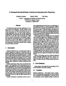
The following sections describe, as an example, a working implementation of this architecture using National Instruments LabVIEWTM programming environment. The system functional diagram is shown in Figure 1. In this case: the shell program manages the execution and display of three modules, the SubPanels contain the modules User Interface, and the configuration file, specific for this system, identifies which modules are to be used and other parameters.
Another task for the shell is the monitoring of the status of each module by checking the module watchdog variable so that if anything is failing an automated corrective action can be initiated and can be communicated to the operator. Also, depending on the functionality defined for the application, the shell can communicate to the modules when the shell is terminated so that all the modules can be gracefully terminated if so desired. Figure 1 System functional diagram
C. Data Exchange Mechanism In order for the modules to function properly, they need to exchange data in a seemingly transparent way that does not add unnecessary time overhead to the process so as to keep the “real time” nature of the application. This mechanism must be independent of module operation. Data, although possibly unchanging, must always be available for modules that use it regardless of whether the source module is executing or not. Data can be exchanged among the modules and between modules and the shell via a system memory area managed by either a system resource or by another program. Access to this area must be carefully managed so that, if there are multiple writers to the same data point, collisions can be avoided. Also, careful consideration needs to be given to some of these data points as to whether they should be initialized or not when the writing module starts. Similarly, when the module terminates, attention should be paid in setting the last data value. Depending upon how the data is used by other modules, the last data value maybe the last data or a default value.
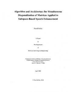
As it is shown in Figure 2, the system described is one of several systems, all operating with the same architecture.
Figure 2 Overall System
A. Module Definition This system shown in Figure 1 is based on a PXI Chassis with hardware modules for general data acquisition and motor control. The software modules defined for this particular system are:
a data acquisition module for a variety of sensors, a motor drive control module, and an information module collecting data from the chassis itself.
The Data Acquisition software module collects data from a variety of sensors connected to multiple hardware modules. The number and type of sensors is programmable. The module can perform preliminary data processing on a predefined set of sensor types and the output is an array of data. The sensor configuration is defined in a text file that can be re-loaded programmatically. Since the output is an unbounded array, adding a sensor of the predefined type can be easily accomplished by modifying the configuration file. If the additional sensor is of a different type, the additional type can be added by stopping, modifying and reloading this module without stopping the other modules. The output array is automatically increased by the appropriate number of elements. The Motor Drive software module controls a motor. It receives commands from the operator via its front panel or other systems. The module is developed such that the hardware is always executing the last command, even if the module is terminated. In this system the hardware may use more than one type of motor drive. Therefore, a separate software module for each drive type is developed and the correct module is selected by the shell program configuration file.
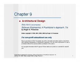
The configuration of the shell is determined by a text configuration file that identifies which module is to be loaded into which sub-panel. This file can be modified as the shell is running and can be re-read with the new information. The following is an excerpt of a configuration file (Figure 3). The shell has a tab control with up to 9 pages available. The first three pages are used; each tab definition line has the label for the tab and a reference to the module to be displayed.
Figure 3 Configuration file excerpt
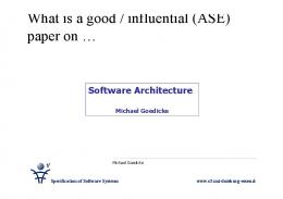
Another portion of the configuration file contains the information necessary to load the module (Figure 4): The module reference in brackets, the path to the module VI, and the path to the module specific configuration file if needed.
The Info software module collects information about the chassis controller such as the amount of disk space left and the temperature of some of its components. B. Shell Program The shell program uses the LabVIEW sub-panel control feature as a way to control the display of the individual module user interfaces. The sub-panel control is a window container used to display the front panel of another LabVIEW program (VI) within the front panel of the shell program. By using sub-panels, the developers provide a structural framework that facilitates consistency in both module software design and user interface appearance. The sub-panels controls are contained in pages of a ‘Tab” control that has a predefined number of pages, but only the one used are visible. The operator can select which page to view therefore having a consistent location for the software module displays. The functions of the shell consist of loading the module GUI into the sub-panel, removing it when the module is being terminated, a mechanism for reloading the module, detecting if the module is inactive by monitoring its watchdog.
Figure 4 Another excerpt from the configuration file
When the module is loaded (Figure 5) it executes as if it was running standalone, but its display is confined to always be in the same position giving consistency. When the module is terminated (Figure 6), via a control within the module, its front panel it removed and replaced by a button control used to re-load the module.
re-deployed without affecting the value of the unchanged variables. This implementation uses shared variables for both data exchange between modules in the same system, and data exchange between applications in different systems over the network.
IV.
ARCHITECTURE BENEFITS
This architecture provides several benefits in both the program development and the program execution environments. Figure 5 Module executing inside a sub-panel
Module development and testing is greatly facilitated as each module can be written and debugged independently from the others and outside the shell managing program. Testing is possibly simpler as it is confined to the inputs and outputs of only one module. Module maintenance is also facilitated as the module is a standalone program entity with its own source code management history. In a system where the application is executing and the LabVIEW development tools are installed, the individual module execution can be debugged as normally performed in a LabVIEW environment. If modifications need to be implemented, the module can be stopped, edited and restarted ‘in place’ without affecting the other modules.
Figure 6 Sub-panel with module terminated
C. Data Exchange LabVIEW has a built-in data exchange mechanism called the Network Shared Variables (Network SVs). Network Shared Variables are used to exchange data between LabVIEW programs executing within the same system or in different systems over a network. Access to these variables is managed by the National Instruments Shared Variable Engine that operates as a service in the Windows operating system environment. Shared Variables are defined and contained in libraries and deployed via the Shared Variable engine. One important feature of Shared Variables is that their values are retained regardless of the execution state of modules that may read or write to them as long as the library/process containing them is not removed from the engine. Also, a Shared Variable library can be modified and
In systems where the application is executing, but the LabVIEW development tools are not installed, only the shell program needs to be in an executable format. In this environment, program module execution cannot be debugged and the modules cannot be edited ‘in place’. They must be modified in a ‘development’ system and then transferred to the ‘executing’ system. However, modules do not need to be re-compiled and can be imported from the development system in source code format. Module re-start is a function of the running managing shell program.
V.
CONCLUSION
This document has described the feasibility of a flexible architecture that allows portions of the code to be modified while the rest of the application continues to execute. Hot pluggable software modules allow data resulting from system hardware modifications to be seamlessly incorporated in the data stream. Use of the described software architecture can greatly improve the long-term availability of the data system functions as well as allow for the addition of new measurements and control functions without disruption of the test in progress.