Software Architecture Modelling and Performance Analysis with Argo/MTE Yuhong Cai1, John Grundy1, 2, John Hosking1 and Xiaoling Dai1 Department of Computer Science1 and Department of Electrical and Computer Engineering2, University of Auckland, Private Bag 92019, Auckland, New Zealand {rainbow,john-g,john}@cs.auckland.ac.nz Abstract. We describe Argo/MTE, an extension of the open-source Argo/UML CASE tool that incorporates software architecture modelling facilities and performance test-bed code generation. We illustrate its application by example and explain the tool architecture and our experience using and evaluating it to date.
1. Introduction Software architecture design and evaluation have become crucial in large scale systems development [4],[6],[8]. Validation of non-functional requirements is particularly critical and one of the most challenging of these to validate is system performance [6], [16], [17]. Existing architecture modelling and performance analysis tools are limited. Many modelling approaches have been taken, from informal visual design environments to formal architecture style specification and verification [5],[8],[13]. Performance analysis approaches range from simulation and rapid prototyping to reference benchmarks [4],[6],[14],[16],[20],[21]. Most have limitations when used on large-scale projects, such as scalability, integration with other development tools, result accuracy, and flexibility. We describe an architecture design environment with performance analysis facilities which extends the Argo/UML open source CASE tool [18] to provide an integrated modelling environment. We added several architecture modelling support features plus extensions to the XMI UML representation to capture architecture attributes. Performance analysis is based on test bed code generation where test code is synthesised, and performance tests run on real hardware and network infrastructure to gain the performance measures. In the following, we provide a motivating example along with a survey of related research. We then overview and illustrate usage of the Argo/MTE architecture modelling and performance analysis environment. We briefly describe the tool’s architecture and implementation, and our experience with the tool. We conclude with a summary and future research.
2. Motivation Consider a complex architecture for internet micropayment allowing many customers to buy information on the WWW on a pay-as-you-go basis, with many
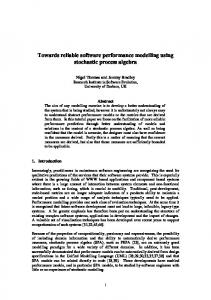
small value transactions [2]. Fig. 1(a) shows an example of such a micro-payment system (NetPay) built using a component-based architecture [3]. When developing such software, architects must be able to model architecture, including many abstractions and their properties: clients, servers, machines, networks, protocols, caching, databases, messages, user interfaces etc in various levels of detail, from overview, refining into successively more detailed designs. Our interest is in how to support architects to gauge likely design performance, even from early, high-level designs [8]. Our approach focuses on generating executable code from architecture specifications and deploying this code on real hardware, to capture realistic timing information supporting incremental design refinement. Many approaches have been used for performance estimation. Benchmarking [4],[6] uses reference architectures and load-testing simple implementations. Relative performances of different technologies used in reference implementations are compared. Benchmarks provide accurate measures for the benchmark application used, but are only a rough performance guide for related applications [6]. Rapid prototyping [11] develops partial software applications implementing performance-critical parts of the code e.g. network-centric and database-intensive. Much effort is often expended for even simple prototypes. If the architecture evolves prototypes must be modified and tests repeated, which is time-consuming and errorprone. Simulation approaches use models of distributed applications to estimate performance. Performance overhead estimates are based on architecture [1],[16] or middleware [12],[17] choices. As these approaches simulate performance, their accuracy varies widely and it is very difficult to obtain performance models for 3rd party applications such as databases.
3. Our Approach In earlier work we developed a custom architecture modelling tool, retrofitting support for performance testbed generation and analysis [7],[8]. Our new approach provides improved modelling and performance test-bed based analysis support within a standard CASE tool. This provides better integrated modelling and analysis support, uses existing model representation formats, and allows simpler refinement of architecture designs to OO
Broker
System Requirements
Customer HTTP Server
HTTPS
Staff PCs
Customer PCs
SQL
CORBA
Browser+EWallet
Bank Application Server
HTTP
EDI; CORBA; Custom
Authorisation
Vendor2
1. Create Domainspecific metamodel(s)
Web Container (JSPs) CORBA
SQL DB Server
6.Visualise test results/modify architecture designs
EJB container (EJBs)
Application SQL
SQL
J2EE Server
Extended XMI
4.Transform XML to test bed code, .BAT files etc
CORBA
socket
Server - C++
3.Generate XML (Extended XMI Format)
SQL DB Server
CORBA
HTTP Server Perl CGIs
Reusable Meta-models
SQL
HTTP
Vendor1
2. Model architecture designs (from requirements)
SQL DB Server
5.Run performance analysis tests
Results DB
.java, .cpp, .bat, .war, …
(b)
(a)
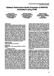
Fig. 1 (a)The NetPay micro-payment system architecture (b) Using the Argo/MTE Environment designs and vice-versa. We chose to extend the Argo/ UML CASE tool [18], [19] to develop Argo/MTE, but the approach is applicable to other modelling tools e.g. Rational Rose™, MS Visio™. Fig. 1(b) shows how our environment is used by architects. (1) Multiple Argo/MTE domain-specific meta-models can be defined, each providing different modelling abstractions and code generators e.g. for webbased or real-time systems, etc. (2) Architecture models are developed using one or more meta-models and multiple design views. System requirements and specifications guide and constrain architecture design choices. (3) An extended XMI model format is used. (4) The model is transformed into files and scripts for code, compilation, database initialisation and deployment. (5) The generated test-bed code is compiled and deployed to multiple host machines and performance tests run. (6) Results are queried and visualised using various graphs which architects use to refine architecture designs and re-generate and run further performance tests. Our approach thus automates the rapid prototyping approach to architecture performance analysis.
4. An Overview of Argo/MTE Usage We illustrate use of Argo/MTE using the NetPay architecture. This is a complex architecture and here we consider only part of its design and one aspect of its performance. Fig. 3(a) shows Argo/MTE modelling an architecture meta-model i.e. a set of modelling abstractions for a particular domain. This example is a web-based enterprise system meta-model, including client, database and, application servers, remote object abstractions, and others. Argo/MTE uses Argo/UML view layout: menu and tool bars (1,2), tree view of model elements (3), diagram editing pane (4), and tabbed property sheet pane (5). The architecture metamodel comprises element types (rectangular icons with
names, stereotypes and properties), element type associations (solid lines), hosting associations (dashed lines), and refinements (solid/dashed black line with one end point). Modelling elements define abstractions that can be composed in a model and their properties. An example of such types and properties is shown in Fig. 2. Associations specify how elements can be related, hosting associations specify how one element type relies on the existence of its host element, and refinements specify how one element type can be refined to a more detailed one. Element Type Client
Main Attributes ClientType (AP, TP) Threads(TP)
RemoteRequest
AppServer RemoteService DBRequest DBTable
RemoteServer (AP, TP) RemoteObject(AP, TP) RemoteMethod(AP, TP) RecordTime(TP) TimesToCall(TP) PauseBetweenCalls(TP) … … … …
Property Description Type of a client e.g. browser, CORBA client. Number of con-current clients run for tests. Name of remote server to call The name of remote object The name of remote service Record time for this? Repetitions Pause duration between calls
Fig. 2. Meta-model type and attribute examples. Architects choose one or more meta-models to use to create views of their architecture design. An Argo/MTE model view comprises elements (rectangles), element requests and services (labels), associations (solid black lines), message interactions (blue lines and highlights), hosting associations (dashed lines), and refinements (solid or dashed black line with one end point). Stereotypes indicate meta-model type correspondences. Each element has a property set derived from its metamodel abstraction. A high-level view for NetPay is shown in Fig. 3(a). NetPay comprises a customer PChosted browser and payment client (“E-wallet”) (1), a broker (2), and several vendor sites (3). The vendor here is a multi-tier architecture: the client browser accesses
Fig. 3. (a) A domain-specific meta-model in Argo/MTE; (b) example architecture model in Argo/MTE. web pages (4), which access application server components via CORBA (5), and a database (6). Each
abstraction links to other abstractions via relationships. Properties/parameters for Reader component
are at the bottom. Architectural parameters (AP in Fig. 2) support architecture modelling e.g. types and relationships. Testing parameters (TP in Fig. 2) support performance code generation, including number of client threads, timing information to record, number of request iterations, and pause between requests. We use a UML class icon-like architecture abstraction notation rather than UML deployment diagram shapes as we found the latter cumbersome and inflexible. Multiple model views are supported for complex specifications. Fig. 4 shows three views of NetPay. Collaboration relationships between client requests and server services (1) visualise/specify message-passing relationships between elements. (2) shows just the message passing relationships between elements. Refinement of higher-level abstractions is shown in (3), where CustomerRegistrationPage service “register Customer()” is refined to constituent operations (each realised by business logic and database operations).
captured in a database (4), which can be queried and graphed in various ways to compare results for different models and implementation parameters. X S LT C o de G en eration S crip ts
< Na m e t yp e =" Stri n g " >Ec o i n In te rf a c e < Ty pe ty p e= "S tr i ng ">J a va B e a n < Ho s t ty p e ="T o m c a t">B ro k e r < Arc h O p e ra ti o n > d oG e n er a te Ec o i n < /N a m e > R ec or d i n g Ti m e 20 < /R e pe ti ti o n> R e m o te Ec o i n M a n a g e rS er ve r R e m o te Ec o i n M a na g e r< /U si n g R e m O b j e c t> c or b a g e n e ra te E co i n< /U s i n g R e m M e th o d > R e m o te Ec o i n M a n a g e rS er ve r R e m o te Ec o i n M a na g e r< /U si n g R e m O b j e c t> c or b a g e n e ra te T an dI< /U si n g R e m M e th od > < /Arc h O p e ra ti o n > < Arc h O p e ra ti o n > d o R e g i ste r< /N a m e > tru e< /R ec or di n g Ti m e > 20 < /R e p e ti ti o n> R e m o te C u st o m e rM a n a g e r Se r v er R e m o te Cu s to m e rM a n a g e r c or b a i ns e rtC u s to m er
X S LT en gin e
1. E xten ded X M I S av e F orm at
A nalysis/ G raph s
pa c ka g e Bro k e r; im p or t j a va .u til. * ; im p or t j a va .io .*; im p or t o r g.o m g .Co sN a m ing .* ; im p or t o r g.o m g .Co sN a m ing .N am ni g C on te x tP a c ka g e .* ;
im p or t R em ote Ec o inM an a g er S er ve r .* ; im p or t R em o te Cu s tom er M a na g e rS e rv er .*; pu b lic cla ss Ec oi nI n et r fa ce e x ten d s Br o ke r._ Ec o in In ter fa c eI m p B l as e {
p riv a et N a m ing Co nte x t nc Re f; p riv a et v o id in itOr b( )
p riv a te R em o te Ec o inM an a g er _R em ote Ec o inM an a g er =n u l ; p riv a te R em o te Cu st om er M a na g e r _ Re m o et Cu s ot m e rM an a g e r=n u ll; p riv a te o rg .o m g .CO RB A.O RB or b ; p riv a te o r g.o m g .CO RB A.O b je ct o b jRe f;
{ try {
} c a tc h ( Ex ce p tio n e ) { e .p r in tS tac k Tra c e ();
o rb = or g .o m g .CO R BA .O R B.in it(); o bj Re f = o rb .re so lv e _in itial _ re fe re n ce s ("N am e S e rv ice " ); n cR ef = Na m in g Co n et x tH elp e r.n a rro w (o b jRe f) ;
}
} pr iv ate v oid g e tRe m o teE co in M a n ag e r( ) { if( _ Re m ote Ec o in M an a g e r!= nu ll) try {
re tu rn ;
if(o rb == nu ll)
C lient H osts
initO rb () ;
Na m e Co m p o n en t n c = ne w Na m e Co m po n e n (t "Re m o te Ec o ni M a n a ge r ", "" ); Na m e Co m p o n en t p a ht [ ] = { nc } ; _ Re m ote Ec o in M an a g e r = Re m o te Ec oin M a n ag e rS e rv e r.Re m o te Ec oin M a n a ge rH e lp er .na rr o w( nc Re f .re so lv e (p a ht ) );
2 . G enerated C o de & S crip ts }
ACT T ool
Jav a A pps
} c a tc h ( Ex ce p tion e ) { e .p rin tS ta c kTr ac e () ; }
D ep lo ym ent T oo l
R esu lts D atabase 4. T est R esults Q ueried and G raph ed
S erver H osts
W eb /J2E E /D atab ase S ervers DBs E JB s
JSP s
3. D eplo yed C om pon ents Initialised an d T ests R un
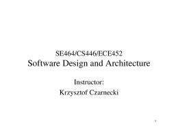
Fig. 5. Running, analysing and presenting results.
(1)
(3)
(2)
Fig. 4. Message associations in Argo/MTE designs and a simple refinement example. Once an architect wants to assess performance of the modelled architecture, Argo/MTE generates test-bed code and runs these tests. A basic assumption in our approach is that code in a component has minimal overhead, and hence performance is dominated by message passing etc through middleware and database access allowing a stub generation approach to still provide good performance data. Fig. 5 shows this process. An extended XMI format represents the design (1). XSLT scripts are run to generate Java, JSP, EJB, ASP and C# code files, and database initialisation, compilation and deployment script files (2). A deployment tool copies, installs, and runs these files on multiple client and server host machines (3). Either thick-client testing applications are generated or Microsoft™ Application Centre Test scripts, used to run thin-client (web) tests. Performance information is
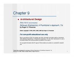
Fig. 6. Example performance analysis results. Fig. 6 shows performance result presentation. Elements have a small circle at left top as a “result available” indicator. Fig. 6(1) shows several such elements, including “Reader” which has evaluation results displayed as a table (2) and bar chart (3). The table shows that each instance of “Reader” issues 10 requests each of tasks doRegister and doGenerateEcoin, taking 510ms (1990ms) to finish the requests, so on average it takes 51ms (199ms) to finish an individual task. The same results as a bar chart are in (3)
5. Design and Implementation Fig. 7 shows key components of our extension of Argo/UML. A meta-modelling tool allows architects to define abstractions for different domains. The metamodel extends the existing Argo/UML XMI-based data representation. We chose to extend XMI as this was the approach used within Argo to represent models, but also to allow our saved architecture models to be partially read by other XMI-capable tools. Modelling tools were developed by specialising the Argo/UML class and collaboration diagramming tools. The Xalan XSLT engine generates code and scripts. We modified a previously developed deployment tool to upload generated files to remote hosts and provide test co-ordination. Generated code captures timing data and stores this in a Microsoft™ Access database. MS Access forms and reports support test database browsing and visualisation. These facilities can readily be extended without modifying Argo/MTE itself. For some tests we generate thick-client applications to act as server invocation and data capture components. For thin-client systems, we generate configuration scipts for Microsoft™ Application Centre Test (ACT), which is instructed to carry out the tests and provide basic result visualisation, useful for load testing web applications. Argo/UML CASE Tool XMI Model
Extended XMI XSLT Engine XMI File
XSLT Code Generation Scripts
Class, Collaboration Diagram Views Architecture Modeller
Architecture Meta-Model Deployment Tool Client
Results Display
Code, Scripts
Results DB
Remote Servers Remote Hosts
Fig. 7. The architecture of Argo/MTE.
6. Discussion and Conclusions We have used Argo/MTE to model and test several software architectures and have compared generated performance results against that of actual implemented applications for accuracy. Applications modelled
include several variants of thick and thin-client versions of an on-line video application [8], a Java Pet Shop application [15], substantial parts of NetPay [3], and several architectural approaches to an enterprise application integration (EAI) support system [9]. Argo/MTE successfully modelled these diverse architectures. The meta-modelling tool permitted us to define allowable modelling abstractions tailoring metamodels for thin-client and thick-client application modelling. We predominantly used the structural architecture modelling facilities to define clients and their requests, multi-tier servers, server objects, web components and relationships, and databases and tables. More complex architectures like the EAI and NetPay systems used multiple views with collaboration and substructural abstractions to manage the modelling complexity. Modelling abstractions of Argo/MTE were mostly sufficient. Exceptions included complex, multielement arguments to remote functions e.g. CORBA sequences and complex transactional logic e.g. multicheckpoint transactions. Collaboration diagrams were useful for specifying dynamic behaviour but UML-style sequence diagrams would be useful to better capture operation sequencing. We successfully generated for J2EE and .NET test bed code for each system. We performance tested these applications using one or more SQL Server 2000 database servers. Some applications had pre-existing implementations in both J2EE and .NET (video system and Pet Shop), others had implementations in Java, J2EE, Java Messaging Service and CORBA (NetPay and the EAI application). We ran the same generated performance tests on the original, hand-implemented applications as were run on the generated test-beds. Some hand modification of these generated tests was needed to add correct argument values to properly drive hand-implemented servers. In general, performance results obtained from the generated test-bed code are accurate, with detailed Argo/MTE models producing performance results within 20-40% of the handimplemented applications. Larger variances occurred with systems with complex business logic (conditional execution of substantial remote object and database services) and complex transaction processing logic as these violate our assumption of low overhead of such code. For some implementation technologies, including Java Messaging Service and .NET web services, we had only rudimentary code generators, resulting in inaccurate generated code. We also discovered implementation deficiencies in the hand-implemented video and micro-payment systems which needed correction to sensibly compare their performance to the test-beds (a useful result in its own right). Our performance test database proved useful to capture all
test results in one place and allow complex analysis and result visualisation. Implementing and modifying XSLT code generators proved relatively time-consuming and improved support for this is needed. We envisage a small IDE within the tool to specify XSLT constructs and corresponding Argo/MTE extended XMI data, with ability to run parts of the code generator over test cases. The performance visualisation support is basic and needs improving. The XMI extensions are arbitrary, although they are a significant improvement on the proprietary architecture model format our previous work used. The format used may require revision as standardisation occurs in the representation of architecture information in UML and XMI. One final area for improvement is to permit users to specify ranges of values for testing parameters e.g. number of concurrent users and server threads. Ranges of averaged performance values could then be collected rather than a single average performance measure. We have described extensions to a CASE tool for software architecture modelling and performance test bed generation. Argo/MTE provides graphical views for specifying performance test bed meta-models and architecture design diagrams stored as an extended XMI representation. This is used to generate a performance test bed, which, when run, produces relatively accurate performance results. We have demonstrated utility of the environment by modelling several architectures and favourably compared generated test-bed performance to that of hand-implemented versions of these systems.
References [1] Balsamo, S., Simeoni, M., Bernado, M. Combining Stochastic Process Algebras and Queuing Networks for Software Architecture analysis, Proc 3rd Intl Wkshp Software & Performance, 2002, ACM Press. [2] Dai, X. and Grundy, J.C. Customer perceptions of a thinclient micro-payment system: issues and experiences, J. End User Computing, 15, No. 4. [3] Dai, X. and Grundy, J.C. Architecture for a Componentbased, Plug-in Micro-payment System, Proc 5th AsiaPacific Web Conference, Sept 27-29 2003, Xi’an, China, LNCS 2642, pp. 251-262. [4] ECPerf Performance Benchmarks, August 2002, ecperf.theserverside.com/ecperf. [5] Gomaa, H., Menascé, D., and Kerschberg, L. A Software Architectural Design Method for Large-Scale Distributed Information Systems, Distributed Systems Engineering J., Sept. 1996, IEE/BCS. [6] Gorton, I. And Liu, A. Evaluating Enterprise Java Bean Technology, In Proc Software - Methods and Tools, Wollongong, Australia, Nov 6-9 2000, IEEE. [7] Grundy, J.C. and Hosking, J.G. SoftArch: Tool support for integrated software architecture development, IJSEKE, Vol. 13(2), 2003,. 125-152. [8] Grundy, J.C., Cai, Y. and Liu, A. Generation of Distributed System Test-beds from High-level Software
Architecture Descriptions, Proc 2001 IEEE Intl Conf on Automated Software Engineering, San Diego, CA, Nov 26-29 2001. [9] Grundy, J.C., Bai, J., Blackham, J., Hosking, J.G. and Amor, R. An Architecture for Efficient, Flexible Enterprise System Integration, Ptoc 2003 Intl Conf on Internet Computing, Las Vegas, June 23-26 2003, CSREA Press, pp. 350-356. [10] Grundy, J.C., Wei, Z., Nicolescu, R. and Cai, Y. An Environment for Automated Performance Evaluation of J2EE and ASP.NET Thin-client Architectures, Proc 2004 Australian Conference on Software Engineering, Melbourne, April 14-16 2004, IEEE CS Press. [11] Hu, L., Gorton, I. A performance prototyping approach to designing concurrent software architectures, In Proc of the 2nd International Workshop on Software Engineering for Parallel and Distributed Systems, IEEE, pp. 270 – 276. [12] Juiz, C., Puigjaner, R. Performance modelling of pools in soft real-time design architectures, Simulation Practice & Theory, 9, 2002, 215-40. [13] Kazman, R. Tool support for architecture analysis and design, In Proc 2nd International Workshop on Software Architectures, ACM Press, 94-97. [14] McCann, J.A., Manning, K.J. Tool to evaluate performance in distributed heterogeneous processing. Proc 6th Euromicro Wkshop Parallel & Distributed Processing, IEEE, 1998, 180-185. [15] MSDN, Using .NET to implement Sun Microsystem’s Java Pet Store J2EE BluePrint application, October 2002, http://msdn.microsoft.com/library/default.asp? url=/library/en-us/dnbda/html/psimp.asp. [16] Nimmagadda, S., Liyanaarachchi, C., Gopinath, A., Niehaus, D. and Kaushal, A. Performance patterns: automated scenario based ORB performance evaluation, Proc 5th USENIX Conf on OO Technologies & Systems, USENIX, 1999, 15-28. [17] Petriu, D., Amer, H., Majumdar, S., Abdull-Fatah, I. Using analytic models for predicting middleware performance. In Proc 2nd Intl Wkshop on Software and Performance, ACM 2000, pp.189-94. [18] Robbins, J.E. and Redmiles, D.F. Cognitive Support, UML Adherence, and XMI Interchange in Argo/UML, Proc CoSET’99, Los Angeles, May 1999, University of South Australia, pp. 61-70. [19] Robbins, J. Hilbert, D.M. and Redmiles, D.F. Extending design environments to software architecture design, Automated Software Engineering, vol. 5, No. 3, July 1998, 261-390. [20] Subraya, B.M., Subrahmanya, S.V. Object driven performance testing of Web applications, Proc 1st AsiaPacific Conf Quality Software, IEEE, 17-26 [21] Web Application Testing, WAPT Version 2.0, http://www.loadtestingtool.com/.