Page 1 of 9
IET Cyber-Physical Systems: Theory & Applications
This article has been accepted for publication in a future issue of this journal, but has not been fully edited. Content may change prior to final publication in an issue of the journal. To cite the paper please use the doi provided on the Digital Library page.
IET Research Journals
Submission Template for IET Research Journal Papers
Software Defined Dynamic QoS Provisioning for Smart Metering in Energy Internet Using Fog Computing and Network Calculus
ISSN 1751-8644 doi: 0000000000 www.ietdl.org
Lina Huang1 , Yi Liu2 , Jun Wu3∗ , Gaolei Li4 , Jianhua Li5 1 −5 School of Electronic Information and Electrical Engineering, Shanghai Jiao Tong University, 800 Dongchuan Rd., Shanghai, China * E-mail:
[email protected]
Abstract: Energy Internet (EI) is a revolution of power systems due to its flexible energy control. The smart meters are the key components in EI which perform real-time monitoring and require high demands on Quality of Services (QoS). Besides, due to the great performance on resolving device-interconnecting and realizing overall network control, Software Defined Networks (SDN) is considered as a trend for future EI. However, most existing software defined EI have all the data processed at SDN controller which makes it difficult to realize fine-grained and deep edge computation and control. Meanwhile, most existing QoS provisioning cannot provide satisfying service for EI because various metering data from smart meters require different time-variant QoS guarantees. To address above challenges, we propose a software defined dynamic QoS provisioning for smart metering in EI using fog computing and Network Calculus (NC). Firstly, a software defined EI architecture, where fogs are deployed on smart meters and base stations to realize edge services, is proposed to perform deep edge control in EI. Secondly, the software defined dynamic QoS provisioning based on NC theory is proposed to guarantee QoS. Simulations of latency as well as bandwidth utilization show the advantages of the proposed scheme.
1
Introduction
Recently, more and more researches have focused on Energy Internet (EI) which integrate various energy forms into communication systems and provide two-way real time communication between the grid and users[1-2]. As EI is still a new type of electronic technology, there still exists several challenges need to be solved like complexity, efficiency, reliability and security[1].To improve the efficiency in EI, Software Defined Networks (SDN) which have a great performance on resolving devices interconnecting, realizing monitoring and controlling for the overall network is considered as a trend for future EI. In [3], a SDN based EI architecture is proposed to realize local energy information monitoring. In [4], an energy-aware routing model is proposed combined with SDN to take the consideration of energy when deciding communication path. Besides, the implement of programmability of energy flows into EI is proposed in [5]. However, most existing software defined EI process all the data at SDN controller which is exerted all data processing and monitoring pressure, thus these schemes cannot realize fine-grained and deep edge computation and control. Besides, smart meters and sensors in EI which are deployed to monitor the real-time power consumption require totally different Quality of Services (QoS) due to various energy infrastructures they linked to[1, 6]. Although software defined EI has a great performance on energy routing, it ingores the concerning of increasing number of smart meters and sensors in EI which require high demands for dynamic Quality of Service (QoS). However, software defined EI are mostly focus on the energy router without the concerning of increasing number of smart meters and sensors in EI which require high demands for dynamic Quality of Service (QoS). Existing dynamic QoS provisioning methods in traditional networks cannot be directly used in software defined EI. These QoS policies mainly have two limitations. Firstly, most of them only change one abnormal QoS policy without global control [7, 8]. Secondly, only one QoS parameter is concerned in guaranteeing QoS such as latency or bandwidth [9, 10]. Therefore, the issue about dynamic QoS provisioning in software defined EI is still unresolved.
IET Research Journals, pp. 1–9 c The Institution of Engineering and Technology 2015
To address these challenges, we propose a hierarchical fog computing advanced software defined EI architecture. Based on this architecture, a network calculus based QoS anomaly prediction mechanism and dynamic software defined QoS provisioning scheme are proposed. The main contributions of this paper are as follows. Hierarchical fog computing advanced software defined EI architecture: We introduce fog computing into software defined EI architecture to realize locally information processing and reduce the latency. The fogs are deployed on two layers as base stations layer and smart meter layer. For the underlying energy infrastructures, they communicate with the nearest meter fogs. For meter fogs, they can manage the states of underlying infrastructures and handle some tasks which can be processed locally. Before sending the data to base station fogs, they will preprocess the data due to the content aware function of fog computing. For base station fogs, they can communicate with the nodes from same layer and adjacent layers. Base station fogs are responsible for data forwarding and QoS guarantees. Besides, the SDN controller is responsible for managing the overall network states, deciding the QoS provisioning policies and controlling of the whole network. Dynamic QoS anomaly prediction and provisioning: First of all, QoS policies are designed based on Network Calculus which makes it possible to predict the network anomalies such as latency and backlog and lets the base station fog initiatively requesting for QoS provisioning. Besides, dynamic QoS provisioning is realized by SDN controller and the request as well as response of QoS provisioning are in the form of FlowTables. For our proposed architecture, meter fog plays a role of content classification. The base station fog is responsible for QoS anomaly prediction and QoS guarantee. The SDN controller needs to generate QoS policies and provisioning and make an overall control. Therefore, this scheme can realize a two-way communication and aware of anomaly in time. The remainder of this paper is organized as follows. Section II introduces related works. Our proposed hierarchical fog computing advanced software defined EI architecture is described in Section III. Section IV describes the network calculus based QoS anomaly
IET Review Copy Only
1
IET Cyber-Physical Systems: Theory & Applications
Page 2 of 9
This article has been accepted for publication in a future issue of this journal, but has not been fully edited. Content may change prior to final publication in an issue of the journal. To cite the paper please use the doi provided on the Digital Library page.
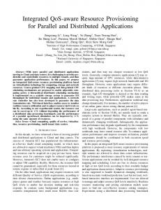
Fig. 1: The architecture of fog computing advanced software defined EI architecture prediction. The software defined QoS provisioning is presented in Section V. Section VI presents the design of fogs and SDN controller. Simulation and analysis are demonstrated in Section VII. Finally, Section VIII draws a conclusion.
advanced EI have not be proposed, the architecture of it and the specific structure of each component is blurry and need to be further explored. 2.3
2
Related work
2.1
Energy Internet and software defined Energy Internet
Energy Internet is the comprehensive use of advanced power electronics technology and information technology to achieve multiple way of energy sharing and information exchange [2]. In [11], a future renewable electric energy delivery and management system (FREEDM System) is proposed to integrate energy generating sources and storage with existing power systems. A distributed energy resources services platform is proposed to coordinate the distributed energy resources and renewable energy integration [12]. Besides, as it is complex to configure traditional networks, SDN is proposed to separate the control plane and data plane to achieve a flexible network traffic control [13]. It offers an chance to change the limitations of current network resources [14]. For example, the authors apply the SDN into WSNs to realize the network management in [15]. Therefore, SDN has also been widely used into EI to virtualize networks and leave the underlying sensors only data related functions [16-18]. In [5], the authors proposed the SDEI architecture which separates the control, data and energy planes to realize flexibility and efficiency. In [16], the network subsystem utilized SDN to connect all the devices together. In [17], SDN enable the dynamic network control in the consideration of specific communication requirements in power grid. As we can see, the SDN offer EI better network management and configuration. Although many researches focus on software defined smart grid or EI, the dynamic QoS provisioning problems for smart metering in EI have not been solved yet. 2.2
Fog computing
With the explosively increasing number of sensors and data, cloud computing is utilized on many traditional sensor networks [19- 21]. As sensors are heterogeneous and dynamically changing which contribute to numerous different types of data and cost massive time to process, cloud computing cannot well solve them and the sensor networks require a more flexible and compatible architecture [22]. To deal with this issue, many researches are focusing on fog computing, which is localized and extends the distant cloud to the edge of network [23]. In [24], edge computing is utilized to realize edge caching for mobile social networks. Furthermore, fog computing has a better performance on processing data and controlling underlying sensors as it is more efficient and easier to access compared with cloud computing. The fog layer is deployed between WSNs and cloud layer in architecture [25]. Besides, a data delivery mechanism is designed. In [26], the fog nodes are deployed above the WSNs and manage all the nodes inside a fog coverage area. As the researches on fog
2
QoS provisioning methods
Guaranteeing QoS for the numerous types of data is a important goal in network [1, 27-29]. Recently, researches are focusing on dynamic QoS mechanism as different data type requires different QoS requirements [30, 31]. A multi path routing protocol is proposed which can make different data choose different routing mechanisms but it is not suitable for real time applications [32]. Authors in [33] propose to consider QoS each time receiving a packet but this may cause data backlog when mass data arrive. Some consider to change QoS policies timely in [34] but it is not suitable for the network which covers several data types. In [35], a QoS provisioning based on energy aware is proposed. These QoS provisioning methods only care about each signal data packet without concerning of overall network states. As every packet will be influenced by other packets arrived at the same node, how to provision QoS still need future consideration. Moreover, as fog is content aware, it has the ability to distinguish the data into more types in a fine-grained way. Besides, these data may change their QoS requirements with the changes of network and application states. Therefore, the existing QoS mechanisms cannot be directly utilized in EI and make full advantages of SDN.
3 Proposed fog computing advanced software defined EI architecture In this part, the architecture of fog computing advanced software defined EI architecture and a brief introduction of QoS provisioning are proposed. This fog computing advanced software defined EI architecture includes the basic components as energy infrastructures, meter nodes, base stations and cloud center and attaches them new responsibilities. Fog computing is deploying on meter nodes and base stations. The cloud center also plays a role as SDN controller. This architecture contains four layers, as shown in Fig. 1, including energy infrastructures layer, meter fog layer, base station fog layer and SDN controller in cloud layer. The energy infrastructures layer contains numerous underlying energy infrastructures. The smart meters play a role in acquiring electricity information, monitoring electricity quality and managing energy. Therefore, sensors are running on different protocols to support different functions or applications and need the route information when sending data. However, in our proposed architecture, the underlying sensors do not need to care about the heterogeneous network convergence problems and route information and only need to send the energy related data to the local meter fog nodes. The first fog layer is deployed at meter fog nodes which are originally local based. As fog computing is content aware, the nodes complete the data preprocessing which helps classify data into different types based on content. Also, they monitor underlying sensors and upload these information. After
IET Review Copy Only
IET Research Journals, pp. 1–9 c The Institution of Engineering and Technology 2015
Page 3 of 9
IET Cyber-Physical Systems: Theory & Applications
This article has been accepted for publication in a future issue of this journal, but has not been fully edited. Content may change prior to final publication in an issue of the journal. To cite the paper please use the doi provided on the Digital Library page.
classifying, meter fog will attach a type ID for the upper fog to distinguish the type and do further processing. The second fog layer is deployed at base stations which have more flexible resources. The data forwarding and QoS guarantee are realized in this layer. The nodes inside this layer have the ability to communicate with each other among the same layer. The base station fogs service for data forwarding and QoS anomaly prediction. Different data types are allocated different amount of computing and communicating resources. The computing resources are represented as data processors, and the quantity of processors allocated data type equals to the allocated number of computing resource. Also, each data processor corresponds to a QoS anomaly prediction table which can detect network anomaly based on NC theory. Once anomaly occurs, the base station fog will initiatively request for QoS provisioning. The requested object is the SDN controller which is deployed at cloud center. It contacts to all the base station fogs and has a strong ability of computing and storage. Therefore, it regulates the whole network state and issues QoS policies generation and provisioning. It is clearly to see that the meter fogs are at the edge of underlying energy infrastructure sensors, the base station fogs are at the edge of meter fogs. They are localized relatively and preprocess part of local data, which is not limited to QoS provisioning, before sending to next layer. The detailed information about anomaly prediction, QoS provisioning and deployment systems of fogs and SDN controller will be introduced in the remaining parts.
4 QoS anomaly prediction based on network calculus Network Calculus theory is a network performance analysis tool which can be used to calculate the bounds of performance parameters based on arrival curve and service curve [36]. Therefore, with the upper bounds of latency, backlog and so on, systems can process network abnormal on time to guarantee the overall performance of the network [37, 38]. In our proposed QoS anomaly prediction mechanism, we utilized two main concepts from NC theory as arrival curve and service curve. The QoS policies are designed in the form of service curves. Along with arrival curves computed from each processor in base station fog, many parameters related to QoS can be easily computed and thus future predict QoS anomalies. 4.1
Data Shaping
Processor m is assigned a time slot ∂i to forward data type i in one time period T . Obviously, the most efficient way to send data packets is sending as many packets as possible during allocated time. For this idea, we forward data after shaping into same size packets in one processor. The time interval ∂i is set in the consideration of jitter in order to avoid packet loss. As we can see from Fig. 2.a, the data shaping in single processor allows the processor try its best to send packets in the allowed time ∂i . When all processors follow the data shaping rule, the bandwidth can be well utilized in one base station fog as shown in Fig. 2.b. To simplify our description, the size of packets of each data type i is defined as: Si = B ∗ (∂i − σi )/T (1) The Si represents the size of packets the processor i shaping the data into. B represents the bandwidth of the base station fog. T represent the time interval for all processors finishing sending one shaped packet. The ∂i represents the allocated time for processor i sending shaped packets in one period T . σi represents the jitter limit value. 4.2
Arrival curve and service curve in Network Calculus
The data flow inside base station fog is described in Fig. 3. When data flows arrived at the fog, they will be sorted and shaped based on the type label. Each processor has time interval ∂i to send the
IET Research Journals, pp. 1–9 c The Institution of Engineering and Technology 2015
Fig. 2: Data shaping packets in a time period T . Therefore, the queue delay can be concerned as time period T . During this process, each processor has the responsibility to record the arrival data amount from the packet analysis module as arrival curve ACi (t). The service curve SCi (t) is defined as: SCi (t) =
Zt
B ∗ (∂i − σi )/T dt
(2)
0
As we know, the QoS is guaranteed based on the allocated computing resources, bandwidth and so on. The allocated time to send packet for data i in time T is ∂i , the jitter limit value is σi , the allocated computing resource is represented as j, which means data i is allocated j processors to process it. Therefore, the QoS policies can be described as a set of each processor’s service curve along with the data type it processed. 4.3
QoS anomaly prediction
Network parameters concerned with QoS can be calculated by arrival curve and service curve. The QoS anomaly prediction and new QoS provisioned based on the computed QoS parameters are shown in Fig. 4. At the very beginning, several critical QoS parameters values are set such as backlog critical value BLcrit and latency critical value DLcrit . As we can see from Fig. 4, the current delay DLcompand and backlog BLcomp can be easily computed from arrival curve and service curve. When anyone of the computed value is larger than the critical one, the processor will predict it as QoS anomaly and request for new provisioning. These QoS policies includes the resources allocation and the service curves for different data types.
5 Software defined based dynamic QoS provisioning As is described above, base station fogs act as predictors for future QoS anomalies and the SDN controller acts as a solver providing the soluations, which means provisioning new QoS policies. 5.1
Modeling of resource configuration
As we know, the QoS provisioning includes two parts as resource configuration and forwarding policy provisioning. The configuration of resource will be discussed first. The latter part of QoS provisioning is mainly about forwarding policy. As we concerned, different data type should be configured different resources. Therefore, we consider a network of a set of N data types which is defined as: T y = [ty1 , ty2 , . . . , tyi , . . . , tyn ], 1 ≤ i ≤ n
(3)
Also, the resources in the fog node are divided into numerous processors. We consider a base station fog node with M processors
IET Review Copy Only
3
IET Cyber-Physical Systems: Theory & Applications
Page 4 of 9
This article has been accepted for publication in a future issue of this journal, but has not been fully edited. Content may change prior to final publication in an issue of the journal. To cite the paper please use the doi provided on the Digital Library page.
Fig. 3: Data flow inside the base station fog 5.2.1 Acquiring and processing classified data in base station fog: Acquisition module stores the table which describes the data type in corresponded processors. Once a data packet arrives, this module will extract the type label and then send to related processor according to it data type. Data processing includes three steps which are executed in the processors. Processors firstly will change the size of shaped data based on service curve. At the same time, each processor saves a QoS anomaly prediction table, in which the anomaly values are set by the SDN controller. Once the computed value of parameter is bigger than the critical one, the processor will send the anomaly message to configuration module. Then, each processor will send its arrival curve and QoS anomaly prediction table to configuration module once required by configuration module.
Fig. 4: QoS anomaly prediction as: P ro = [pro1 , pro2 , . . . , proj , . . . , prom ], 1 ≤ j ≤ m
(4)
Once the corresponding data type processing is allocated to each processor, for example whether the data type tyi is allocated to processor proj to process can be defined as: ( 1 proj is allocated to tyi f (x) = (5) 0 proj is not allocated to tyi Therefore, the overall allocated matrix Cor can be defined as: Cor11 · · · Cor1j · · · Cor1m .. .. .. . . . Cor = Cori1 · · · Corij · · · Corim (6) . .. .. .. . . Corn1 · · · Cornj · · · Cornm
The number of processors allocated to data type tyi is defined as: Sumi =
m X
Corij
(7)
i=1
The Sumi represents the amount of resources allocated to process that type of data. The more processors allocated to one data typer is equal to more resources configured to that data type. 5.2
Procedures and FlowTables design of QoS provisioning
For one data type, QoS policy includes the service curve which decides the network parameters for how to send it and the resource allocation which decides how much processors will be allocated to process it. For one processor, QoS policy means which data it needs to process and how to send the data. The main procedures and related FlowTables participate into the provisioning are described in Fig. 5. The detailed information about procedures and FlowTables related to QoS provisioning are described in the following part.
4
5.2.2 Configuring QoS policies in base station fog: As shown in Fig. 5, configuration module serves for receiving the anomaly messages from one processor and then ask all processors to send the arrival curve and QoS anomaly prediction table. After collecting all the information, it transfers these information together into the form of FlowTable and then send to the SDN controller. Once received the FlowTable of QoS provisioning, configuration module transfers the table into QoS anomaly prediction tables, service curves and sends them to corresponding data processors. Also the relationship between data types and processors will be sent to acquisition module. 5.2.3 Packet analyzing and QoS provisioning in SDN controller: When a packet arrived at the SDN controller, once packet analysis module find that is a request for QoS provisioning, this module will send this packet to QoS provisioning module. QoS provisioning module is the key part during the whole provisioning stage. The basic step is the transfer between the FlowTable and provisioning information. When the request table arrived, it will extract the data process information including arrival curves, QoS related parameters value. Then it will obtain pervious emplace of service curves and parameters set logs from the log database. Based on these information and the information from the FlowTable of QoS provisioning request, the QoS provisioning module computes the best combination of QoS policies which will then be sent in the form of the FlowTable of QoS provisioning to the fog nodes. 5.2.4 The table of QoS anomaly prediction: The table includes the critical values of QoS parameters such as latency, jitter and backlog. Once these parameters are computed abnormal by the service curve and arrival curve, the anomaly sign will be set to 1. This table will be sent to the SDN controller when there is exists QoS provisioning requesting. 5.2.5 The FlowTable of QoS provisioning response: The FlowTable includes three components as match, action and counter. Obviously, the action represents QoS provision requests and the counter is SDN controller. Besides, the match contains the information required for QoS provisioning. As SDN controller has saved the pervious policies, the flow table only need to contain the ID of fog and those that are currently calculated as arrival curve, QoS related parameters value.
IET Review Copy Only
IET Research Journals, pp. 1–9 c The Institution of Engineering and Technology 2015
Page 5 of 9
IET Cyber-Physical Systems: Theory & Applications
This article has been accepted for publication in a future issue of this journal, but has not been fully edited. Content may change prior to final publication in an issue of the journal. To cite the paper please use the doi provided on the Digital Library page.
Fig. 5: Dynamic software defined QoS provisioning 5.2.6 The FlowTable of QoS provisioning response: The action in this FlowTable is QoS provision and the counter is the ID of fog. The match part has to contain all sets of each processors as is shown in Fig. 5. The parts of processor ID and type ID allocate computing resources to each data type. The parts of time and jitter decide the service curve. The parts of jitter, latency and backlog decide the QoS anomaly prediction table. If both the type change and provision change are set to 0, it means this processor does not need to change the configuration.
Fig. 6: Dynamic QoS provisioning sequences
5.3
Dynamic QoS provisioning Sequences
In this part, the detailed QoS provisioning and data forwarding sequences will be described chronologically and are shown in Fig. 6. Step 1: The energy related data is sent to the nearest meter fog node with the information of source address and destination address. The underlying energy infrastructure sensors do not need to care about how to forward data any more.
IET Research Journals, pp. 1–9 c The Institution of Engineering and Technology 2015
Step 2: When the meter fog receives the data packets, as it is content aware, it classifies data type according to content and attaches a label which records the data type at the end of each packet. After classification, the meter fog sends packets to the nearest base station fog. Step 3: The base station fog starts to extract label from packets in the acquisition module which stores a table recording the relationship between processors and data types. Once obtained the label, the module sends data to the corresponding processor. As the sizes of packets are different, data shaping is the first step when the data arrives at processor. Different processors will shape the packets into different sizes according to the allocated bandwidth and jitter, therefore the service curve can be computed based on them. Each processor will record the arrival amount of packets as the arrival curve. Step 4: With the arrival curve and service curve, latency, buster and other parameters can be predicted. Different types of data will be set different abnormal values according to QoS policies. Once the parameters are close to the abnormal threshold, the processor will proactively send the QoS provisioning request. Then, the base station fog collects all processors’ states and sends as the form of FlowTable. The detail of FlowTable for requests of QoS provisioning is described in pervious part. Step 5: The SDN controller will reconfigure the QoS policies, resource allocations and anomaly values of each data type. These parameters will be transferred in the form of FlowTable. The FlowTable of QoS provisioning is described in the previous part. Step 6: When the FlowTable of QoS provisioning is sent to the nearest base station fog, the configuration module of base station fog will abstract the data process information including arrival curves, QoS anomaly prediction tables and the corresponding relationships between processors and data types. Then it resets the configuration of each processors and acquisition module. Step 7: When the destination sensor does not belong to the base station fog, the base station fog will request SDN controller for the route information. Step 8: As SDN controller has the overall sight, it can find out which base station fog the destination sensor it belongs to and then feedback the route information to it. Step 9: The base station fog will then forward this packet to another base station fog which covers the destination node.
IET Review Copy Only
5
IET Cyber-Physical Systems: Theory & Applications
Page 6 of 9
This article has been accepted for publication in a future issue of this journal, but has not been fully edited. Content may change prior to final publication in an issue of the journal. To cite the paper please use the doi provided on the Digital Library page.
6
Implement models of fogs and SDN controller
In this part, the detailed design of two kinds of fogs and SDN controller which are related to QoS provisioning are presented. 6.1
SDN controller involves dynamic QoS provisioning
SDN controller layer serves dynamic QoS provisioning, router information providing and the whole network monitoring and managing.
Fig. 8: Implement of base station fog the number of data types and one data type may be processed by different number of processors at different conditions according to the QoS polices provisioned by SDN controller. That is to say, each type of data will be processed under different compute resources, bandwidth to meet different QoS requirement according to dynamic QoS polices and QoS abnormal detection based on network calculus. The configuration of processors are completed by configuration module ˘ Z´ state are monitored by state management modand meter fogesâA ule. Besides communicating with underlying meter fogs and SDN controller, base station fogs also have the ability to communicate with other fogs in the same layer. Fig. 7: Implement of SDN controller 6.3 As is shown in Fig. 7, on one side, SDN controller is responsible for the QoS provisioning. With the QoS abnormal detection mechanism, SDN controller does not need to care about the data processing in base station fogs until the request of QoS provisioning comes. After receiving the request, the SDN controller will generate new QoS provision policy and then send to base station fogs in the form of FlowTable. Also, the request of QoS provisioning is sent in the form of FlowTable. Based on the local management idea, which means meter fogs are responsible for the management of underlying sensors and base station fogs are responsible for the management of meter fog nodes, SDN controller can only manage the states of base station fog nodes. On the other side, based on a global sight of the network, SDN controller can manage the whole network and provide route forwarding information. Also, base station fogs can ask SDN controller for route information. That is to say, more data can be forwarded by the base station fog instead of the central controller. 6.2
Base station fog involves QoS anomaly prediction
The base station fog is one of the most important components in the network and serves as QoS anomaly prediction and QoS provisioning requesting. As described in Fig. 8, the base station fog contains four main modules as storage module, acquisition module, data processor module and management. After the preprocessing of the data in meter fogs, the acquisition module in base station fogs can easily distinguish data types and process them according to types based on the labels attached on the data packets. Then, processes will process the data based on QoS policies. The storage module saves the QoS policies related data as QoS service curves, computing resources and QoS policies logs. The requesting of QoS provisioning, monitoring of processors’ states, managing of local network topology and sensors’ state are executed in managements. The software platform inside the base station fog has several processors. Each processor has same amount of resources and processes one data type at one time. The number of processors is more than
6
Meter fog involves content classification
In traditional EI, all the energy infrastructures send energy related data to the nearest meter node and then forward to core network. These sensors follow different transmission protocols and make it a problem for meter node to forward them. The meter fog is suitable to be deployed on the meter node and solve this issue. Besides, as fog nodes are content aware, they can classify data according to content. Therefore, the base station which manages numbers of meter nodes can reduce the time to process data. The heterogeneous network convergence module and fog smart gateway contact underlying energy infrastructures and meter nodes for receiving and forwarding data. The monitoring module collects sensors’ state includes power, resources, service and so on. Also, it monitors local network topology. As one base station fog may manage several meter fogs, this preprocessing can prevent large number of data waiting from being sorted and attached labels at the base station fog node and reduce the delay. Also, it makes full use of local resources. Besides the data classification role based on the fog’s ability of content aware, the meter fogs play another role to monitor the status of the underlying nodes including energy, position and so on. This information will finally be collected in the SDN controller.
7
Simulation and results
In this section, we simulate the proposed hierarchical fog computing advanced software defined EI and software defined dynamic QoS provisioning under the consideration of the scalability of network and fine-grained control. 7.1
Evaluations of scalability
In Energy Internet, new energy infrastructures will join into the network continuously depending on the change of time-domain. Therefore, to verify the scalable capability of the proposed hierarchical fog computing advanced EI architecture as well as the dynamic QoS provisioning scheme, bandwidth utilization simulations are done with different network scale. In this circumstance,
IET Review Copy Only
IET Research Journals, pp. 1–9 c The Institution of Engineering and Technology 2015
Page 7 of 9
IET Cyber-Physical Systems: Theory & Applications
This article has been accepted for publication in a future issue of this journal, but has not been fully edited. Content may change prior to final publication in an issue of the journal. To cite the paper please use the doi provided on the Digital Library page.
IET Review Copy Only
IET Cyber-Physical Systems: Theory & Applications
Page 8 of 9
This article has been accepted for publication in a future issue of this journal, but has not been fully edited. Content may change prior to final publication in an issue of the journal. To cite the paper please use the doi provided on the Digital Library page.
IET Review Copy Only
Page 9 of 9
IET Cyber-Physical Systems: Theory & Applications
This article has been accepted for publication in a future issue of this journal, but has not been fully edited. Content may change prior to final publication in an issue of the journal. To cite the paper please use the doi provided on the Digital Library page.
[21] Chatterjee, S., and Misra, S.: ’ Target tracking using sensorcloud: sensor-target mapping in presence of overlapping coverage’. IEEE Communication letter, Aug 2014, 18(8), pp. 1435–1438
[38] Al-Zubaidy, H., Liebeherr, J. and Burchard, A.: ’ Networklayer performance analysis of multihop fading channels’. IEEE/ ACM Transactions on Networking, Feb 2016, 24(1), pp. 204-217
[22] Ali, A.W., and Parmanand.: ’ Energy efficieny in routing protocol and data collection approaches for WSN: a survey’. 2015 International Conference on Computing, Communication and Automation, Noida, India, May, 2015, pp. 540–545 [23] Aazam, M. And Huh, E.N.: ’Fog computing: The CloudIoTIoE middleware paradigm’. IEEE Potentials, 2016, 35(3), pp. 30–44 [24] Su, Z., Xu, Q. Hou F., et al: ’Edge caching for layered video contents in mobile social networks’. IEEE Transactions on Multimedia, 2017, unpublished [25] Zeng, J., Wang, T., Lai, Y., et al.: ’Data delivery from WSNs to cloud based on a fog structure’. 2016 International Conference on Advanced Cloud and Big Data, Chengdu, China, 2016, pp. 104–109 [26] Naranjo, P.G.V., Shojafar, M., et al.: ’A new stable electionbased routing algorithm to preserve aliveness and energy in fogsupported Wireless Sensor Networks ’. 2016 IEEE International Conference on Systems, Man, and Cybernetics, Budapest, Hungary, Oct, 2016, pp. 2413–2418 [27] Balen, J., Zagar, D., Martinovic, G.: ’ Quality of Service in Wireless Sensor Networks: A Survey and Related Patents’. Recent Patents on Computer Science, 2011, 4(3), pp.:188–202 [28] Su, Z., Qi, Q., Xu, Q., et al: ’Incentive scheme for cyber physical social systems based on user behaviors’. IEEE Transactions on Emerging Topics in Computing, 2017, unpublished [29] Hui, Y., Su, Z. and Guo, G.,: ’Utility based data computing scheme to provide sensing service in Internet of Things’. IEEE Transactions on Emerging Topics in Computing, 2017, unpublished [30] Li, H., Zhang, J., Hong, Q., et al.: ’QoS-aware channelwidth adaptation in wireless mesh networks’. IEEE International Conference on Communications, Malaysia, 2016, pp:1–6 [31] Phakathi,T., Lugayizi, F., Isong, B., et al.: ’Quality of Service of Video Streaming in Vehicular Adhoc Networks’. International Conference on Computational Science and Computational Intelligence, Las Vegas, NV, United states, 2016, pp:886–891 [32] Long, Z. and Su, M.: ’Research on Quality of Service in Wireless Sensor Networks’. International Conference on Information Engineering and Computer Science, Beijing, China, 2011, pp. 312-315. [33] kader, M.E.E.D.A.E. Youssif, A.A.A. Ghalwash, A.Z.: ’ Energy aware and adaptive cross-layer scheme for video transmission over wireless sensor networks’. IEEE Sensors Journal, Nov 2016, 16(21), pp. 7792-7802 [34] Lemeshko, O.V., Yeremenko, O.S., Hailan, A.M.: ’Investigation of multipath QoS-routing dynamic tensor model’. IEEE International Conference on Electronics and Information Technology, Odessa, Ukraine, May 2016 [35] Alam, M.M., Razzaque, M. A., Mamun-Or-Rashid. M., et al.: ’ Energy-aware QoS provisioning for wireless sensor networks: Analysis and protocol’. Journal of Communications and Networks, Aug 2009, 11(11), pp 309-405 [36] Fidler, M., and Rizk, A.: ’A guide to the stochastic network calculus’. IEEE Communications Society, July 2014, 17(1), pp. 1553-887X [37] Bben, R., Fidler, M., and Liebehen, J.: ’ Stochastic bandwidth estimation in networks with random service’. IEEE/ ACM Transactions on Networking, Apr 2014, 22(2), pp. 484–487
IET Research Journals, pp. 1–9 c The Institution of Engineering and Technology 2015
IET Review Copy Only
9