Software Defined Radar: synchronization issues and practical implementation ∗ [Invited Paper]
†
G. Aloi
A. Borgia
S. Costanzo
G. Di Massa
DEIS-UNICAL Rende-ITALY
DEIS-UNICAL Rende-ITALY
DEIS-UNICAL Rende-ITALY
DEIS-UNICAL Rende-ITALY
[email protected]
[email protected]
[email protected] [email protected]
V. Loscrí
E. Natalizio
P. Pace
F. Spadafora
DEIS-UNICAL Rende-ITALY
INRIA Lille, FRANCE
DEIS-UNICAL Rende-ITALY
DEIS-UNICAL Rende-ITALY
[email protected]
[email protected]
[email protected]
ABSTRACT
[email protected]
In recent years, the research and industry world have focused on the concept of Software Defined Radio (SDR) The impetus of SDR research is the aim to shift the radio engineering problem from the hardware to the software domain. The main advantage of this problem-space transition is that the software domain provides a more flexible, repeatable, accessible solution space than that provided by the hardware domain. GNU Radio [2] is an open source software-defined radio project and the Universal Software Radio Peripheral (USRP)[7] is the hardware specifically designed to be used with the GNU Radio software. The combination of these two technologies has been considered to implement low cost and very sophisticated software defined radios. Software Defined Radio and Software Defined Radar are really one in the same technologies, it stands to reason that GNU Radio and Categories and Subject Descriptors the USRP can be utilized to form a low cost radar sensor. B.4.1 [Input/Output and Data Communications]: Data In practice, the Software-defined radar is a particular radar Communications Devices—transmitters, receivers ; system where the hardware is substituted with the software, D.2.6 [Software Engineering]: Programming Environments— by applying the same concepts of the SDR. Integrated environments, Graphical environments In Software Defined Radar, most signal detection and radar processing are performed by FPGA and/or DSP. Since the Keywords radar platform is completely software defined, it can adapSoftware Defined Radio, Software Defined Radar, GNU Ratively switch between different operation modes for radar dio, USRP. by modifying both transmit waveforms and receive signalprocessing tasks on the fly. Thus, depending on the application scenario, the radar firmware can be changed and 1. INTRODUCTION the radar transceiver can behave as linear/non-linear chirp ∗This work has been carried out under the framework of radar, traditional pulsed radar with phase encoded modSTEM-Net:“STEM” devices for self-organizing wireless Netulation or non-traditional-waveform radar. This approach works, National Italian Project ] 2009S7RLXY financed by considerably reduces the number of components, and hence the Italian Ministry of University and Research. the cost, size, weight, and power consumption. †All authors are listed in alphabetic order and they conThe Communication Engineering Lab (CEL) at the Karltributed equally to the writing of the manuscript. sruhe Institute of Technology (KIT) developed an open source software package within the Simulink-USRP project that enables owners of an Universal Software Radio Peripheral, also known as USRP, to build models in SimulinkTM that interface with the hardware in realtime. This latter has many functionalities with respect to GNU Radio and it allows an optimal functions elaboration, so that many applications can be realized. Moreover, the transmitted signal can be treated with different mathematical elaborations by considering MatlabTM and SimulinkTM tools (it is not possible to The present work is focused on Software Defined Radar (SDR) paradigm, which gives a more versatile solution when compared to classical radar systems. Thanks to this new system model, most of the fundamental operations, such as signal generation, filtering, up and down conversion, are easily implemented via software. The objective of this paper is to show the main issues related to the design of an effective Software Defined Radar device. Specifically, we will discuss and face the synchronization issues existing between a received and a transmitted signal when an open source hardware, namely the Universal Software Radio Peripheral (USRP), is considered.
make this through GNU Radio). For this reason in this work we considered Simulink in order to make our practical experience with USRP. The main advantage of software defined systems is related to the great flexibility and accessibility owned by this kind of systems with respect to hardware systems. As a matter of fact, a single SDR system can implement many radio (or radar) systems with different hardware, by only changing the software. Software requirements represent the main issue of this kind of systems. Specifically, in order to be useful as a radar sensor, the system must be capable of transmitting and receiving data such that the time between pulse transmission and reception could be known exactly. In order to characterize our system, we analyze in details time-coherence and time-synchronization. A stream of digital data samples is said to exhibit time-coherence if a time value can be assigned to each sample such that the difference in the time values assigned to any two samples is equal to the difference between the actual times at which the samples were converted either to, or from, an analog signal. In practice, a system is said to be time-coherent when the discrete data signal accurately represents its analog counterpart in time. Two streams of digital data are said to lack time-synchronization if each stream is time-coherent within itself, but the two streams are not time-coherent with respect to one another. In radar systems, time-synchronization must exist between the transmit and receive data streams and in this work we focus on this aspect. The remaining part of the paper is organized as follows: Section 2 presents a few recent works on the implementation of challenging Software Defined Radar systems; section 3 explains the issues related to the integration of USRP hardware and software SimulinkTM tools in order to implement an SDRadar architecture whilst the results obtained by the conducted tests and the related synchronization issues are presented in section 4. Finally, section 5 concludes the paper by proposing future research directions on this exciting field.
2.
RELATED WORKS
In the last years, the development of this new open software and hardware technology has gained a great impact. Many scientists and researchers are focusing on Software Defined Radio systems. In the follows, we consider some contributions of Software Defined Radio systems. Zhang et al. [5] propose a measurement system making use of a hybrid radar scheme with frequency modulation continuous wave and a pseudo-random code pulse techniques. Authors show the capability to obtain high level precise information concerning the velocity of a vehicle, the distance, the direction and other information useful to improve the security in the automotive field. In [4] authors consider an experiment based on the usage of a SDR to implement a basic radar system and then synthetic aperture radar. This experiment gives a next step closer to establishing the concept of a cognitive radar. It shows important results in order to highlight the issues and the limitations related to the combination of the SDR with radar systems. In [1] authors show the capability of the USRP technology of realizing a passive radar demonstrator by designing a low-cost DVB-T software defined passive radar system for costal ship detection; more recently, Garmatyuk et al. [3], design a multifunctional software-defined unit well suited for radar sensor networks, which can be used for range measurements, radar imaging and data communi-
cations. To the best of our knowledge, despite to the cited works, this is the first software defined radar implementation using the Simulink toolbox interface instead of the well known GNU Radio to configure the USRP device.
3.
SDRADAR IMPLEMENTATION
In this section we focus on specific aspects relative to the development of a Software Defined Radar by considering in particular the integration of USRP devices and Simulink tools. The synchronization problem between the received and the transmitted signal will be specifically faced.
3.1
Basic principles of a Radar system
It is worth to recall the basic principles of a radar system. The way a radar works is very simple: the transmitting antenna illuminates the scene with an electromagnetic wave impinging on any objects and undergoes a phenomenon of backscattering. The scattered field is partially collected from the same antenna, switched on the receive mode. The delay between the transmission and reception times allows an estimation of the distance (ranging) relative to the various objects, leading to locate targets in the direction of a range. In order to recognize echo signal, the transmission does not occur continuously, but with rectangular pulses of duration τ . Let us indicate as Rsr the slant range, that is the distance between the target and the radar. We have: Rsr = c ∗ t/2
(1)
where c is the free-space velocity and t is the time interval between the transmitting and the receiving instants of the pulsed signal.
3.2
The synchronization issue
In order to have a system that works correctly, it is needed a good level of synchronization. A stream of digital data samples is said to exhibit time-coherence if a time value can be assigned to each sample such that the difference in the time values assigned to any two samples is equal to the difference between the actual times at which the samples were converted either to, or from, an analog signal. In practice, a system is time-coherent when the discrete data signal accurately represents its analog counterpart in time. Two streams of digital data are said to lack time-synchronization if each stream is time-coherent within itself, but the two streams are not time-coherent with respect to one another. In our specific case, by considering a train of pulses, the synchronization is guaranteed whether the first pulse is detectable both in transmission and in receiving and the delays between the pulses are constant. In Figure 1 we show the main blocks of a Software Defined Radar system. The temporal synchronization is guaranteed whether the exact interval between the first pulse transmitted and the first pulse received are exactly determined. In order to guarantee the synchronization, we follow the Patton’s approach [8] and use a 50Ohm coaxial cable to connect T x and Rx doors of the daughter-boards 2.b. We transmit a known synchronization signal representing a preamble, then we transmit the radar waveform and we measure the fixed delay between the transmitted and the received signal.
4.
SYSTEM TESTING
Figure 3: Simulink model.
Figure 1: A block scheme of the Software Defined Radar [8]. Figure 4: AM-DSB modulation in the TRANSMISSION subsystem. implement the hardware functions whilst the software layer 1, programmed through Simulink tools, generates and stores the waveforms. (a)
(b)
Figure 2: a) Layers scheme of the system in synchronization phase [8] - b) USRP configuration for the synchronization procedure.
The synchronization procedure as considered in the previous section, requires the Software Defined Radar system to be able: • to generate a synchronization signal (preamble); • to generate a waveform to be transmitted; • to convert the preamble and the waveform from software to hardware; • to transmit the generated waveform; • to receive the preamble; • to receive the transmitted waveform; • to transform both the received signals from hardware to software; • to measure the delay due to hardware and software processing. It is worth to notice that the radar shows a structure very similar to the ISO/OSI stack protocol layer with only three levels as shown in Figure 2. The capability of this prototype to perform the considered task has been tested into the laboratory. Layers 2 and 3
4.1
The Simulink Model
Simulink allows to interface a personal computer with an USRP through the software model shown in Figure 3. The whole signal (preamble and waveform) is generated into the block T X, that is linked with the subsystem block called T RAN SM ISSION , where the signal modulation occurs. In our test we consider a simple AM-DSB modulation as depicted in Figure 4. The modulated signal is transferred to the block USRP SINK that allows the signal transmission. The block USRP SOURCE receives the transmitted signal that is delivered to the RECEP T ION block,where the signal is demodulated and successively stored into a vector implemented within the RX block.
4.2
Test
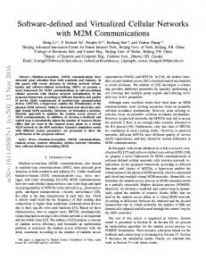
In order to evaluate our system performance, we conduct some tests by putting as input to the system pulses trains with different lengths. The RFX2400 2.4 GHz transceiver daughterboard is used in radar testing by following the tuning and the calibration procedure presented in [8]; the pulse duration time is set to 2sec., the amplitude, as quantization levels, is equal to 5 and the waveform is sampled with a frequency sampling f s = 125 KHz. In the follows, we show the results obtained by comparing the transmitted and the received signals. Specifically, we consider three case, relative to 2 pulses, 3 pulses and 12 pulses, respectively. As shown in the figures 5.a, 5.b and 5.c there is not synchronization between the transmitted and the received signal. Specifically, we can observe that the arrival instants of the waveforms are different; the durations of the received pulses are different in every considered cases; moreover, there is a lot of amplitude variation. We can observe as in Figure 5.c around the time of 20sec. (after 2.5 × 10⁶ samples) the receiving signal is more fitting with the transmitted signal. In particular,
(a)
(b) (a)
(b)
(c)
Figure 5: Temporal reconstruction of sent pulses: a) 2 pulses b) 3 pulses and c) 12 pulses.
the duration of the pulses is equal to the duration of the transmitted pulse and the amplitude shows a linear shape. This analysis reveals the presence of a transitional stage that deserves further investigation. As suggested from authors in [6] we add a preamble to the waveform. Specifically, we consider preambles with different durations, equal to 10, 30 and 60 sec. in order to evaluate whether the duration of the preamble has some influence on the system synchronization. In fact, the presented results show that both the preamble and the pulse sent as test, are correctly and completely received in each considered case, even if the received signal starts to be synchronized only in the final phase of the transmission. In practice, the bit duration of the transmitted and received signals are equal after some time of transmission as shown in Figures 6.a, 6.b and 6.c. This analysis validates the need for a preamble in order to obtain a satisfactory synchronization level; nevertheless, the use of a long preamble wastes a lot of bandwidth, so that SDRadar applications could be extremely inefficient. In order to overcome this drawback, we consider two potential solutions: a) the optimization of the preamble in terms of duration; b) the elimination of the preamble by considering interpolation and decimation factors to tune the input and output velocity of the buffer.
4.3
The preamble optimization
From the previous analysis and tests, we noted as the two signals (the transmitted and the received) start to be synchronized after about 20 seconds from the transmission starting point. For this reason we consider a preamble of 22 seconds and we test the results by considering different random waveforms (i.e. 01010110010 × 2 and 11001110110 × 2) in order to be sure that the synchronization is not influenced by a specific waveform. In Figures 7 and 8 we can observe as different shape of waveform do not influence the synchronization. Of course, we make many different tests not reported here for lack of space. Moreover, we can observe as the frame is correctly received after 22 seconds and the duration of the transmitted bits is exactly the same of the
(c)
Figure 6: Transmission and reception of a pulse preceded by a preamble of different lengths: a) 10 seconds b) 30 seconds and c) 60 seconds.
Figure 7: Preamble of 22 seconds (01010110010 × 2) followed by a single pulse.
duration of the received bits. Thanks to the use of Simulink and Matlab softwares, we easily compute the hardware delay when the synchronization is realized through the use of a a preamble, by obtaining a fixed value of tHW = 8.37589sec.
4.4
The preamble elimination
The FPGA module on board of the USRP can execute decimation and interpolation operations. In practice, the FPGA adapts the bit flow to the USB buffer. The interpolation consists in adding samples to the data flow from the computer to the USRP, and the decimation corresponds to the elimination of some samples within the data flow from the USRP to the computer. Those operations are calibrated through the interpolation and decimation factors (N and D respectively). The interpolation with a N factor consists into the addition of N null samples every two samples and it is translated with the increase of the sampling frequency. The decimation consists in the capture of 1 sample after D
(a)
(b)
Figure 8: Preamble of 22 seconds (11001110110 × 2) followed by a single pulse.
Figure 9: Reception of a train of pulses reducing the sample rate: a) 5 pulses b) 7 pulses.
samples, by decreasing the sampling frequency. We choose both the interpolation and the decimation factors to avoid both the “USRP under-run” and “USRP over-run” working conditions (respectively, there are not enough samples to be sent for the computer to the USRP board and viceversa). We choose an interpolation factor N of 256 corresponding to a sampling rate in input to the board equal to 500 Ksample/sec and a decimation factor D equal to 32 corresponding to a sampling rate of 2 Msample/sec at the computer input.
to configure the USRP open hardware; moreover, we investigated the synchronization issues related to the radar system that became more marked because of the delays introduced by different hardware and software levels within the SDRadar architecture. The obtained results validated the proposed system by showing different solutions (long random preamble or interpolation and decimation factors tuning) to measure and reduce the processing delay according to the desired accuracy level of the received signal. Future research will be focused on specific system testing within different frequency bands in order to further validate and make the system even more general, robust and attractive.
4.4.1 System Testing We apply as input to the system different pulses trains with different durations. The signals considered for this test are square waves with a period of 1 second and dutycicle of 50%. We consider different tests by sending a single pulse, 3, 5 and 7 pulses. In the follows (figures 9.a and 9.b), we only show the results for a number of 5 and 7 pulses. Results show that: • the received signal is complete; • the received pulse durations are the same as that relative to the transmitted pulse; • the amplitude value (expressed in terms of quantization levels) is constant; • the delay due to the hardware processing is smaller with respect to the case with a preamble. Specifically, we measure the hardware delay, equal to tHW = 0.50432sec., whilst the duration of the pulse is equal to τ = 0.50376sec. In practice, with respect to the transmitted pulse having a duration of 0.5sec., we have a very small percentage of error equal to 3%, always keeping constant the τ delay. For the sake of clarity, we would like to remark that this good synchronization level without using a preamble and after accounting the fixed processing and propagation delay, has to be paid in terms of reduced localization accuracy due to maximum sampling rate of 2 Msample/sec for the received signal.
5.
CONCLUSION
In this paper we presented the implementation of a Software Defined Radar system using a specific Simulink tool interface
6.
REFERENCES
[1] A. Capria, M. Conti, D. Petri, M. Martorella, F. Berizzi, E. Dalle Mese, R. Soleti, V. Carulli, “Ship Detection with DVB-T Software Defined Passive Radar.” IEEE Gold Remote Sensing Conference, 2010. [2] E. Blossom, “Gnu radio: Tool for exploring the radio frequency spectrum.” Linux Journal, 12(122), 2004. [3] K. Kauffman, D. Garmatyuk, J. Schuerger, “Multifunctional software-defined radar sensor and data communication system”. IEEE Sensors Journal, 11(1):99–106, 2011. [4] C. Prathyusha, S.N. Sowmiya, S. Ramanathan, R. Soman, K.P. Amrita, V. V. Deepthi, M. Chinnam, J. Nandhini, “Implementation of a low cost synthetic aperture radar using software defined radio.” International Conference on Computing Communication and Networking Technologies (ICCCNT), 2010. [5] Hui Zhang, Lin Li, Ke Wu “24ghz software-defined radar system for automotive applications.” European Conference on Wireless Technologies pages 138-141. Munich, Germany, December 2007. [6] M.R.Inggs, L. Williams, “Low cost networked radar and sonar using open source hardware and software.” IET International Conference on Radar Systems, pages 1-5, 2007. [7] Ettus Research LLC, “Universal software radio peripheral - usrp.” http://www.ettus.com/. [8] Lee K. Patton, “A GNU Radio Based Software-Defined Radar.” Master Thesis, http : //etd.ohiolink.edu/view.cgi?accn um = wright1176142845 2007.