IEEE CHILECON2015 - ISSN xxxx-xxxx, Pág. xxxx.xxx. Santiago de Chile, 28 al 30 de Octubre 2015
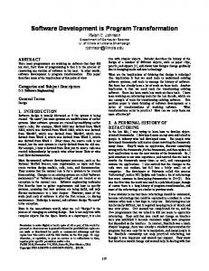
Software Development to program and operate a CRS A255 Robotic Handler (Desarrollo de Software para la Programación y Operación del Manipulador Robótico CRS A255) Douglas Casa, Danilo Coque, Darwin Alulema & Derlin Morocho Abstract— This project optimizes the performed operation on the Robotic CRS A255 handler. The robot uses electronic boards connected to the current controller through I2C communication to ensure its correct functioning. Moreover, the graphic interface software which includes a compiler allows the user to control the handler robot through commands. Furthermore, the control software has similar textual guides and online and offline programming features. Keywords—Robotic Handler CRS A255, I2C Communication, Serial Communication, Compiler and command interpreters, Simultaneous movement algorithm
the human body. It is built with five degrees of freedom or joints that are compound of a hip, shoulder elbow, wrist and its rotator. In addition, the robotic handler has a final effector or gripper, which allows it to manipulate different kinds of objects.
I. INTRODUCTION Currently, large-scale industrialized processes include robot handlers with more features. These processes have allowed the development of hardware and software applications to comply with all the requirements, which imply optimizing resources, reduced operating times, and quality improvement in the final product. Therefore, it is important to develop open source applications that can be innovated and complemented through time. The paper’s proposal is to put robotic handlers back into operation and not to depend on providers that use close sources. In addition, after a previous study and analysis, the project is divided into two stages. The first stage optimizes control and power boards, which allow the 5-joint motion at the same time. This operation is performed through motion algorithms. The second stage involves the design and development of open source software by selecting commands, which not include robot’s math. Furthermore, an interpreter compiler is incorporated to the software, which allows data transfer from the controller to the computer and vice versa. Consequently, the robotic handler will be provided with a great deal of functionalities.1 II. CRS A255 ROBOTIC HANDLER The robotic handler has an anthropomorphic configuration which means that it is anatomically similar to the upper limb of Douglas Casa was with the Electronic Engineering Department, Universidad de las Fuerzas Armadas - ESPE, Sangolquí, Ecuador (
[email protected]). Danilo Coque was with the Electronic Engineering Department, Universidad de las Fuerzas Armadas - ESPE, Sangolquí, Ecuador (
[email protected]). Darwin Alulema is with the Electronic Engineering Department, Universidad de las Fuerzas Armadas - ESPE, Sangolquí, Ecuador (
[email protected]).
Figure 1 CRS A255 Robotic Handler TABLE I.
CHARACTERISTIC CLASSES OF THE CRS A255
Structure Drive System Total weight
Five degrees of freedom Electro mechanic DC motors 19 Kilograms
brakes
One brake for each excepting the first joint. Electric-pneumatic driver 1 kilogram.
Final effector connection Useful nominal load
joint
The controller that actually governs the CRS A255 robotic handler is not from the factory, but it is from the first stage of the controller update. Therefore, a new controller named CAD was designed and implemented, and its study and analysis consist on three design stages: A. Feeding Stage Feeding Stage It is the stage in charge of supplying the required voltage and amperage for the proper system operation. It takes power from the mains and couples it to the system requirements. The implemented system has also two different power supplies.
Derlin Morocho is with the Electronic Engineering Department, Universidad de las Fuerzas Armadas - ESPE, Sangolquí, Ecuador (
[email protected]).
IEEE CHILECON2015 - ISSN xxxx-xxxx, Pág. xxxx.xxx. Santiago de Chile, 28 al 30 de Octubre 2015 B. Power Stage It is the stage in charge of signal conditioning and driving the motors and the solenoid from the controller. In addition, it provides the necessary power to handle a pneumatic gripper. Lastly, the electric requirements of each motor are 35 Volts DC and S Amperes.
Provide the software with the necessary capacity. Provide in and out put ports for the interaction of the robotic manipulator in its environment. A. Power Board Design The two remaining activation circuits belonging to the motors that were not working must be activated so that the robotic handler has a proper performance. It also must be considered that the five motors controlling the joints have to work simultaneously. In addition, each motor is protected with independent fuses from possible current variations or possible damages, which can be presented during their manipulation. Furthermore, it contains fuse holders in the frontal outside of the chassis for an easy replacement of deficient fuses. In the following block diagram it is described the changes that will be performed to the power board. FRENO 5
FRENO 4
Botón2 RELÉ
FRENO 3
FRENO 2
BUS DE CONTROL DE FRENOS Y SOLENOIDE SO LENO IDE
SEÑAL DIGITAL DE ACTIVACIÓN
Botón1 RELÉ
SOLENOIDE
Botón LCD
Botón FUSIBLES
FUSIBLE 1 FUSIBLE 2 FUSIBLE 3 FUSIBLE 4 FUSIBLE 5 FUSIBLE 6
BUS ACTIVACIÓN DE FUSIBLES
RELÉS 35 VDC
FUSIBLE 1
CIRCUITO Botón ACTIVACION MOTOR 1
FUSIBLE 6
CIRCUITO Botón Y FRENOS SOLENOIDE
FRENO MOTOR 2 FRENO MOTOR 3 FRENO MOTOR 4 FRENO MOTOR 5
CONTROL MOTOR 1
FUSBLE 2
CIRCUITO Botón ACTIVACION MOTOR 2
FUSIBLE 4
CIRCUITO Botón ACTIVACION MOTOR 4 GIRO MOTOR 1
CONTROL MOTOR 2
CONTROL MOTOR 4
GIRO MOTOR 2 GIRO MOTOR 3 GIRO MOTOR 4 GIRO MOTOR 5
Botón LCD
FUSBLE 3
CIRCUITO Botón ACTIVACION MOTOR 3
FUSBLE 5
CONTROL MOTOR 3
CIRCUITO Botón ACTIVACION MOTOR 5 CONTROL MOTOR 5
BUS DE CONTROL DE MOTORES
Figure 2: Operating diagram of the control board
It can be seen in Figure 2 that it will adapt a bus to allow the connection between the fuse holders in the outside of the case with the power board. The finished work of the implemented and assembled card in each class is shown in Figure 3.
SEÑAL DIGITAL DE ACTIVACIÓN
SERIAL (TX)
Circuito del Microcontrolador
Botón LCD 1
SERIAL (RX)
Botón
LCD’s
MAX 232
IN(1-4)
“MAESTRO”
TEACH PENDANT
OUT(1-4)
E/S DIGITALES
In order to accomplish with all the proposed expectations is necessary to make some modifications to the control and power stages. The system requires: The simultaneous 5 join performance of the robotic handler.
B. Control Board Design It is necessary that the different types of operating systems (manual and online mode) work together, meaning that the system receives orders from the “teach pendant” and other commands. The actual “master” microcontroller was replaced by a PIC 18f452. The main reason, for which it was decided to work with this component, was that its memory capacity quadruples the capacity of the current microcontroller. It also allows future implementation of new options and advanced control techniques. In addition, five “slaves” microcontrollers PIC 16f88 will be used. When working with a microcontroller per each joint, the resources and capacities can be taken advantage to the maximum. This consideration allows the implementation of new alternatives to control the motor. For instance, Figure 4 represents the block diagram that shows the new control board design.
I2C (SDA) I2C (SCL)
Circuito del Microcontrolador
Circuito del Microcontrolador
“ESCLAVO A”
“ESCLAVO B”
Botón
Botón
ENCODER 1
Circuito del Microcontrolador Botón
ENCODER 2
“ESCLAVO C”
Botón LCD 2
ENCODER 3 ENCODER 4
Circuito del Microcontrolador
Circuito del Microcontrolador
“ESCLAVO D”
“ESCLAVO E”
Botón
Botón
SEÑAL DE ENCODERS
III. HARDWARE IMPLEMENTATION AND DESIGN
Figure 3: New Power boardCDC2.
ENCODER 5
C. Control Stage The control system has a “master-slave” configuration. The Master starts a bidirectional communication with the computer, and manages the communication with slaves. In addition, slaves are in charge of providing the necessary signals for the circuit drive of each motor in the power board. The “master and slaves” are PIC’s 16f877A.
CONTROL MOTOR 4
CONTROL MOTOR 1
CONTROL MOTOR 3
CONTROL CONTROL MOTOR 5 MOTOR 3
BUS DE CONTROL DE MOTORES
FR ENO MOTOR 4
CONTRO L FR ENO FRENO FRENO SOLENOIDE MOTOR 5 MOTOR 2 MOTOR 3
BUS DE CONTROL DE FRENOS Y SOLENOIDE
Figure 4: Control Board Diagram
The microcontroller receives three input signals from the encoder. It should be emphasized that the integrated circuit 74LS14 was discarded to avoid having pulse losses like it used to happen with the older board. Three signals from the encoder (A, B, Z) are configured like follows: Channel A is connected to pin RA4. This pin has a counter module “Timer 0” that allows the independent carrying of the pulse counting to the main microcontroller program.
Channel B is connected to pin RB0. This pin has an interruption “INT0”, which is useful to know the direction of displacement of one joint.
Channel Z is connected to pin RA3. This pin is used when it is the necessity to know how many revolutions the motor has spun.
The finished work of the implemented and assembled board inside the case is shown in Figure 5.
IEEE CHILECON2015 - ISSN xxxx-xxxx, Pág. xxxx.xxx. Santiago de Chile, 28 al 30 de Octubre 2015
Figure 5: New CDC2 Control board
Figure 6 shows the performed changes of the controller case with new assembled components
RUN
HOME
NOLIMP
FINISH
PITCH
UNLOCK
PAUSE DELAY RUN WAIT INPUT OUTPUT
ROLL CPATH
Design of the algorithm of Motor Positioning An algorithm for the parallel displacement of motors of a localization point (angular coordinates) has been generated. Figure 8 shows the performance of the algorithm of a slave.
POSICIÓN DESEADA 1
POSICIÓN ACTUAL
Figure 6: Robotic Handler case
POSICIÓN DESEADA 2
IV. SOFTWARE IMPLEMENTATION AND DESIGN The developed software (User Graphic Interface), emulates the working environment and certain functionalities of the RobComm software. In addition, it is required to select the commands that do not involve robots’ kinematics and dynamics, and to structure their syntax to send and receive data. Furthermore, since it is a programming software, a compiler is required in order to execute properly the commands, by the robotic handler. Figure 7 presents a case diagram of general use of the system. Sistema de programación y operación Controlador y software Motor enegizado «extends»
«extends»
Mover las articulaciones
Paro de emergencia
Incializar el manipulador (HOME) Operar manualmente (TeachPendant)
Mover simultaneamente
Cerrar Gripper
*
Abrir Grripper *
Mover una articulación
Visualizar Mensajes «extends»
Ejecutar un programa
*
Modo Terminal Ubicar en una localización
* *
Denegar-aceptar envio
Seleccionar el puerto de comunicacion
operador
*
Trabajar en linea de comandos «uses» Abrir el software RobPro Programar archivos de comandos secuenciales
Compilar Comandos
Manipulador robótico
«extends»
Enviar codigos
«uses»
Abrir la ayuda del sistema
Figure 7: Case Diagram of general usage
In order to establish the commands that will be implemented in the software, it was considered those that not required a mathematic model. TABLE II.
COMMANDS OF THE ROBOTIC MANIPULATOR.
Program Control IF
Location
Movement
Operators
HERE
MOTOR
OPEN
WHILE INT VAR
DLOCN
MOVE JOINT READY
CLOSE LIMP LOCK
POSICIÓN DESEADA 3 POSICIÓN HOME
Figure 8: Command MOVE between two points.
In Figure 8 it is known how many pulses have been moved from POSITION HOME to ACTUAL POSITION (PoD) and its sense (Sen). PosD stores the DESIRED POSITION and data [0x01] the direction to which it will move. First case: The DESIRED POSITION 1 is located in the same quadrant as ACTUAL POSITION; therefore, the sense is the same. The displacement of the DESIRED POSITION is greater than ACTUAL POSITION, therefore the number of pulses to move (PosF2) will be the result of PosD minus PosF and the direction remains the same. Second case: DESIRED POSITION 2 is located in the same quadrant as ACTUAL POSITION; therefore, the sense is the same. The displacement of DESIRED POSITION is less than ACTUAL POSITION, so the number of pulses to move (PosF2) will be the result of PosD minus PosF and the sense will be contrary to the current. Third case: DESIRED POSITION 3 is located in the opposite quadrant of ACTUAL POSITION, so the displacement direction changes and the number of pulses to move (PosF2) will be the result of PosD plus PosF, also the sense will be the same as DESIRED POSITION. Figure 9 shows the block diagram of the internal software operation.
IEEE CHILECON2015 - ISSN xxxx-xxxx, Pág. xxxx.xxx. Santiago de Chile, 28 al 30 de Octubre 2015 V. TESTS AND RESULTS
USUARIO
FORMATO
Modo Botón Secuencial
Botón A (COMANDO MAYUSCULAS)
FORMATO
ModoBotón Terminal
Botón A (COMANDO MAYUSCULAS)
GENERACIÓN DE Botón LISTA
The reasons for which it was decided to redesign the control board, was due to pulse losses in the microcontroller counter , because of the inverter shot (LN7414). The evidence to determine these results were conducted with the motor of the first articulation with constant frequency, varying the percentage of duty, in clockwise and anti-clockwise.
VERIFICACIÓN DE SENTENCIAS Botón Y DECLARACIONES
COMPILADOR - INTERPRETE
ANALIZADOR Botón LÉXICO
ANALIZADOR SEMÁNTICO -Toma las 3 primeras letras delBotón comando.
ANALIZADOR Botón SINTÁCTICO
-Analiza la operación ha realizar. -Interpreta la lógica de la instrucción.
ETAPA DE SÍNTESIS -Une parámetros. Botón -Crea variables si es
necesario.
TABLE III.
-Codifica a la nomenclatura del microcontrolador.
EVENTO RECIBO SERIAL -Recibe dato del microcontrolador.
ENVÍO SERIAL
-Informa al usuario (errores, P. emergencia, F. rango).
-Envío de código al maestro.
Botón
Botón
-Guarda Coordenadas.
Microcontrolador Botón
“MAESTRO”
Recibe Estado de Entradas digitales. -Finalización de comandos.
Figure 9. Block diagram of deployed software
When the user interacts with the interface and performs actions such as open, create, edit and delete the admitted commands go to another format stage where they are converted to uppercase, with the objective of standardizing information and avoiding errors. If the terminal working mode is on, the information goes straight to a treatment stage; otherwise, if the sequential mode is on, before going to treatment stage, the commands are entered into a list, where an index is assigned to each one. Once in the list they go to recognition of control statements such as IF, WHILE, VAR, INT, PAUSE; and each command goes to the treatment stage. Following the design algorithm of a translator, it has been decided not to design a compact compiler; but, the union of a compile-interpreter, which will analyze the structure of each command, verify concordance and generate coded instructions for the "master" microcontroller to perform actions. Structure of compiler-interpreter: Lexical analyzer. Synthetic analyzer Semantic analyzer. Synthesis stage. Jlex generates the lexical analyzer of the compiler. Java Cup generates the synthetic analyzer of the compiler. This stage provides information about the operation that the users want to perform on the manipulator. In addition, it determines whether to send parameters or book memory spaces for return data from the microcontroller. Finally, it encodes the command and sends it. Enabling A255 CRS robotic manipulator, consist of components shown in Figure 10.
Freq: 20.2 KHz Duty 25% Duty 50% Duty 75% Duty 100%
Theoretical
Experimental CW (rise)
150 Pulses/ 10ms 300 Pulses/ 10ms 450 Pulses/ 10ms 600 Pulses/ 10ms
144 Pulses/ 10ms 207 Pulses/ 10ms 327 Pulses/10 ms 413 Pulses/ 10ms
Experimental CCW (desent) 166 Pulses/ 10ms 222 Pulses/ 10ms 339 Pulses/10 ms 440 Pulses/ 10ms
In the Table above, the higher percentage of duty, shows substantial loss of pulses avoiding the possibility of determining the proper position of the manipulator. TABLE IV.
Freq: 20.2 KHz Duty 25% Duty 50% Duty 75% Duty 100%
COUNT PULSES WITH CDC2 BOARD.
Theoretical
Experimental CW (raise)
150 Pulses/ 10ms 300 Pulses/ 10ms 450 Pulses/ 10ms 600 Pulses/ 10ms
148 Pulses/ 10ms 298 Pulses/ 10ms 445 Pulses/10 ms 592 Pulses/ 10ms
Experimental CCW (desent) 147 Pulses/ 10ms 297 Pulses/ 10ms 443 Pulses/10 ms 589 Pulses/ 10ms
The pulse loss at high percentages of duty aren`t as significant as was in previous which allows taking a correct count pulse when analyzing angular velocity. A. Pulse Count Testi at each Articulation For pressure testing the commands JOINT, MOTOR, PITCH AND ROLL will be used. It will allow knowing the error percentage in the movement of each motor.
TABLE V.
Theoretical Sentido CW Sentido CCW
Figure 10: Current components of the system.
COUNT PULSES WITH CAD BOARD
PULSE COUNT AND SHIFTED ANGLE ART.1.
Pulse Count 18000 18001 18001
% error 0.005 0.005
Angle Shifted 90º 91º 91º
% error 1.11 1.11
IEEE CHILECON2015 - ISSN xxxx-xxxx, Pág. xxxx.xxx. Santiago de Chile, 28 al 30 de Octubre 2015 TABLE VI.
Theoretical Sentido CW Sentido CCW
Pulse Count 9000 9001 9001
TABLE VII.
Theoretical Sentido CW Sentido CCW
Theoretical Sentido CW Sentido CCW
Angle Shifted 45º 46º 40º
% error 2.22 11.11
% error 0.005 0.005
Angle Shifted 90º 93º 91º
% error 3.33 1.11
that when consecutively transmitting data without delay time, these were lost and the controller performed wrong operations. When trying to send data from the command HERE to the PC, some motors lost its locations. To provide a solution to this problem it was decided to send data with an additional delay from the controller to the PC and vice versa. The sequential data from the PC should considered a time not less than 10 milliseconds, in addition, the minimum dispatch time from the controller must be not less than 250 milliseconds.
PULSE COUNT AND SHIFTED ANGLE ART.4.
Pulse Count 2430 2431 2431
TABLE IX.
% error 0.005 0.005
PULSE COUNT AND SHIFTED ANGLE ART.3.
Pulse Count 18000 18001 18001
TABLE VIII.
Theoretical Sentido CW Sentido CCW
PULSE COUNT AND SHIFTED ANGLE ART.2.
% error 0.005 0.005
Angle Shifted 45º 46º 40º
% error 2.22 11.11
Figure 11: Data reception with command HERE
PULSE COUNT AND SHIFTED ANGLE ART.5.
Pulse Count 18000 18001 18001
% error 0.005 0.005
Angle Shifted 90º 91º 91º
% error 1.11 1.11
The first and fifth articulation perform precise movements, with a small error, the third articulation has a percentage not greater than 5% but is significant when applying the concept of repeatability. The second and fourth articulations have a very high error rate, these errors appear because of perturbation factors such as articulations weight, gravity in the lowering movement, inertia by instant braking that is performed on them. B. Repeatability Tests To perform these tests the commands MOVE, READY and CPATH will be used, these commands allow to go back to scheduled locations the necessary times from a point in any location and move to another point interchangeably. Tests were carried out where all the articulations are moved with a specific angle, and return to the starting position. These repetitive movements simultaneously cause that the robotic manipulator loses its sense of direction of the initial position HOME. This is affected by disturbances that are added to the articulations two, three and four. The results show that the robot has the ability of repeatability, but the significant errors in certain articulations cause that every time that it returns to the item scheduled, the percentage of error increases. C. Data Transmission testing from PC to controller and from controller to PC By sending data using the command MOVE, it was found
Figure 12: Sending data with command MOVE.
VI. ECONOMIC ANALYSIS AND DESIGN The "CRS Robotics" company that designed and built the original controller CRS A255 robotic manipulator and RobCom software for handling, stopped producing more robots and provide maintenance to them, so time is limited technological life the same. As a solution to the rehabilitation and practical use of the robot (robotic manipulator A255) developing a new controller with local technology to replace the original contemplating certain guidelines of factory controller, in the same way that incorporates both software advantages of the original controller is implemented developed Robcom and software and thus not allowing the A255 manipulator becomes obsolete without operation. The design and construction of a controller for the robotic manipulator around the $ 500. To be developed in a free software allows no additional cost to obtain licenses for their operation; and scalable primarily allows for improvements in the functioning of the software at a later project. VII. CONCLUSIONS When performing the control with a single microcontroller the movement of the motor, it increases the resources and for a better system performance, because it does not share memory modules, timers, counters and ports with other motor. For the simultaneous movement of the five articulations of
IEEE CHILECON2015 - ISSN xxxx-xxxx, Pág. xxxx.xxx. Santiago de Chile, 28 al 30 de Octubre 2015 the robotic manipulator, it provides that each slave microcontroller make the decisions for the right operation of a motor, performs calculations for the movement and only depends on the master to receive and send data regardless of the actions that are doing the other slaves. To perform the movement of the manipulator to locations previously saved, it will be implemented an algorithm of simultaneous movements of the five articulations, without complex mathematical development, providing the system with the ability to move from one position to another without having to go through the position HOME, taking into account that it does not generate a specific trajectory. The use of tools and libraries offered by the java language, like Java Cup and JLex have allowed adapting the structure of the commands to a basic compiler. It allows independently of the source program finding out if there is an error in the commands grammar, in order to prevent possible errors, before information is sent to the controller and cause malfunction. To implement the semantic analyzer, it was decided to develop an algorithm to select the first three letters of the userwritten command, this allows optimizing resources of information processing by the PC, making the coding thereof is done in less time. Using thread type classes in software programming is very important because they allow doing threads that are of no consequence in the execution of the main program, so while the user is interacting with the interface, another operation keeps running, regardless of the end of the other operation to start a new action. REFERENCES [1]
Barrientos, A., Peñín, L., Balaguer, C., & Aracil, R. (1997). Fundamentos de Robótica (Firts ed.). Madrid, Spain: McGRAW-HILL. [2] Craig, J. (2006). Robótica (Tercera ed.). México Df: Pearson educación. [3] Gadgets, H. (13 de 12 de 2007). Hacked Gadgets. Obtenido de Toyota robotic musical: http://hackedgadgets.com/2007/12/13/toyota-roboticsmusical-robots/#section3 [4] Galvez, S., & Mora, M. (2005). Compiladores. Málaga: Universidad de Málaga. [5] Kuka. (2013). Kuka-robotics. Obtenido de Products: http://pdf.directindustry.es/pdf/kuka-roboter/nuevos-rapidos-precisoskuka-small-robots/17587-435871.html [6] Maldonado, D., & Sánchez, A. (2013). Estudio, Diseño e implementación de un controlador de tres grados de libertad para el manipulador robótico crs a255. Sangolquí: Escuela Politécnica del Ejército. [7] Mocencahua Mora, D. (2009). Facultad de ciencias electrónicas. Obtenido de Ftp Descargas: http://www.ece.buap.mx/ini/des.html. [8] Ollero Baturone, A. (2001). Robótica Manipuladores y Robots Móviles. Barcelona, España: Marcombo. [9] Platea, & Gonzalez F, V. (2013). Control y Robótica. Obtenido de Clase de robots: http://platea.pntic.mec.es/vgonzale/cyr_0708/archivos/_15/Tema_5.2.ht m. [10] Reyes Cortés, F. (2011). Robótica Control de Robots Manipuladores. México Df: Alfaomega.. [11] Sass, L. (25 de 07 de 2013). Introducción a la Robótica. Obtenido de Universidad de San Francisco de Quito: http://profesores.usfq.edu.ec/laurents/IME440/IME440_RobotManip.pdf [12] Williams, K. (2006). Thinkbotics. Obtenido de Products: http://www.thinkbotics.com/products.html