Proceedings of the 24th International Manufacturing Conference, IMC 24, 2007
SOFTWARE INTERFACE AND VISION SYSTEM FOR A SCARA ROBOT Sean G. McSweeney and William M. D. Wright Department of Electrical and Electronic Engineering, University College Cork, College Road, Cork, Ireland Email:
[email protected];
[email protected] ABSTRACT This work describes the development of a novel software interface for an AML-based IBM 7545 SCARA robotic arm to a host computer, and its subsequent integration into a vision system utilising cross-correlation and other object recognition techniques. The purpose of the work was the development of an ‘intelligent’ robot-centred manufacturing cell capable of recognition, classification and sorting of various randomly orientated components fed into the manufacturing cell. A pressure-sensing feedback controller for the SCARA gripper was also developed, with the gripping pressure controlled through a NI 6259 DAC incorporated into the overall software architecture. The gripper controller could not be implemented via AML, so various software languages were used for the development of the overall software interface including AML, Visual C++, MATLAB and LabVIEW. This upgrade of the original IBM 7545 AML DOS-based system to interface to Windows-based applications required a large degree of manipulation of the data packets on the host in order to make commands intelligible to the controller RS232 uplink. Future work includes the completion of a GUI for the system, the use of neural networks for online ‘pick and place’ decisions, and the optimisation of vision system recognition techniques through the minimisation of the processing required for Fourier Mellin methods using K-means clustering. KEYWORDS: Robotics; Machine Vision; Control 1.
INTRODUCTION
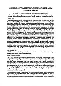
Robots, more specifically robotic arms are the workhorse of a number of the major industries of the world, two of the most well known being the automotive and electronics industries. A robotic arm is most often tailored to the task that it is required to perform, be that pick and place operations or more complex assembly operations. In spite of this level of customisation of robotic arms there are a number of standard configurations [1, 2] including gantry, Cartesian, cylindrical, SCARA and articulated. The link diagram of the SCARA configuration is illustrated in Figure 1. Significant advances have been made in recent years in the area of understanding the kinematics [3-5] and jacobians [6-8] of complex and simple linked structures and this work makes use of many of these advances. Analysis of an isolated robot arm on its own is insufficient to bring it into the context of a manufacturing environment. For the arm to be of any meaningful use it is essential that the supporting architecture for the arm be in place, namely the surrounding workcell.
Proceedings of the 24th International Manufacturing Conference, IMC 24, 2007
Figure 1: Link diagram of SCARA robot. There is a huge number of potential configurations of workcells. The standard workcell consists of a number of sensors and mechanisms to service the central machine, quite often a robotic arm, however in many circumstances the manipulator is not even the central machine in a workcell, but rather a loading mechanism for another machine. The fundamental architecture of a workcell involves a “master-slave” system, in which the intelligent host computer controls the simple sensing devices (through PLC’s (Programmable Logic Controller) if there are PLC’s in the cell or directly if there are not). The hierarchical communication architecture is shown in Figure 2 with a number of typical devices in a manufacturing cell:
Figure 2: Overview of cell architecture. In all manufacturing cells communication standards are extremely important to the continued transfer of data and some automated cell structures could not operate without the sharing of large amounts of data [9]. Control Systems also form an essential part of any work cell. The typical control methodologies employed are simple on/off control applied by the use of a plc (programmable logic controller), however for the purposes of manipulators such as the SCARA tool tip force sensing capabilities are also commonly found [10, 11]. The use of control and control systems is an essential part of the project and thus a section is dedicated to giving relevant background theory on both modelling and implementation.
Proceedings of the 24th International Manufacturing Conference, IMC 24, 2007
Shape recognition is an integral part of any computerised imaging system used in a manufacturing cell and is the thrust of much on-going research [12]. Shape recognition in 2-D space, although less complicated than using 3-D, is far from an easy problem and is a far greater challenge than the previously mentioned edge detection. One of the simplest methods of object recognition is through the use of a template mask matrix of an expected object and convoluting this matrix with the image greyscale matrix to determine the location of the mask within the image matrix. However this method does not account for orientation and scaling of the template matrix, i.e. rotation of the expected object and image size of the expected object due to distance from the camera and homogenous manipulation of the image plane required for robust recognition. 2.
BACKGROUND THEORY
The method of template matching used in this work was simple cross correlation. This method is typically utilised where a background is in motion but the object dimensions remain the same and is ideally suited to optimising speed of recognition. The 2D cross correlation discrete equation is given by: Ma −1 Na −1
C (i, j ) =
∑∑ A(m, n).conj(B(m + i, n + j)) m =0 n =0
(1) ⎧0 ≤ i < Ma + Mb − 1 where ⎨ ⎩0 ≤ j < Na + Nb − 1 which is derived from the estimate of the true cross correlation formula given by the discrete sequence:
⎧ N −m−1 x + y* ⎪ Rˆ xy (m) = ⎨ n=0 n m n ⎪ Rˆ * (− m) ⎩ yx
∑
m≥0
(2)
m