1.5 TECHNOLOGIES TO BE USED . ... 1.5.5 MICROSOFT SPEECH API . ...... So in order to install this IDE two other software will be required, which are Android.
Software Requirements Specification For
DAVID- The personal assistant Mr. Paruraj
Version No. 1.0
Prepared by Amit Sharma
PPIMT
Computer Science & Engineering
22 November, 2016
1
Revision History Date
Version
Description
Author
2
Table of Contents INTRODUCTION ............................................................................................................................................. 5 1.1
PURPOSE ....................................................................................................................................... 5
1.2
SCOPE ............................................................................................................................................ 5
1.3
DEFINITION, ACRONYMS, AND ABBREVIATIONS .......................................................................... 5
1.4
REFRENCES .................................................................................................................................... 6
1.5
TECHNOLOGIES TO BE USED ......................................................................................................... 7
1.5.1
IIS ........................................................................................................................................... 7
1.5.2
ESP8266 Wi-Fi Chip ............................................................................................................... 7
1.5.3
ARDUINO ............................................................................................................................... 7
1.5.4
RASPBERRY PI ........................................................................................................................ 8
1.5.5 MICROSOFT SPEECH API .............................................................................................................. 9 1.6
OVERVIEW ................................................................................................................................... 10
OVERALL DESCRIPTION ............................................................................................................................... 11 2.1 PRODUCT PERSPECTIVE .................................................................................................................... 11 2.2
PRODUCT FUNCTION .................................................................................................................. 11
2.3
USER CHARACTERSTICS ............................................................................................................... 12
2.4
CONSTRAINTS.............................................................................................................................. 12
2.5
ARCHITECTURE DESIGN.............................................................................................................. 13
2.6
USE CASE MODEL DESCRIPTION ................................................................................................. 14
2.7
DATA FLOW DIAGRAMS .............................................................................................................. 15
EXTERNAL INTERFACE REQUIREMENTS ...................................................................................................... 16 3.1 USER INTERFACE ............................................................................................................................... 16 3.1.1 MICROPHONE ............................................................................................................................ 16 3.1.2 SPEAKERS ................................................................................................................................... 16 3.2 HARDWARE INTERFACE .................................................................................................................... 17 3.2.1 WHEELS ...................................................................................................................................... 17 3.2.2 WHEEL BASE ............................................................................................................................... 17 3.2.3 POWER ....................................................................................................................................... 17 3.2.4 SUPPORTING BEAMS.................................................................................................................. 17
3
3.2.5 CHEST ......................................................................................................................................... 17 3.2.6 HEAD .......................................................................................................................................... 17 3.2.7 ARMS .......................................................................................................................................... 18 3.2.8 SENSORS..................................................................................................................................... 18 3.2.9 SERVO MOTORS ......................................................................................................................... 19 3.9.10 MOTOR DRIVER ........................................................................................................................ 19 3.3 SOFTWARE INTERFACE...................................................................................................................... 20 3.3.1 Arduino IDE 1.6.12 ..................................................................................................................... 20 3.3.2 WINDOWS 10 IOT CORE ............................................................................................................. 21 3.3.3 IIS ............................................................................................................................................... 21
4
CHAPTER 1
INTRODUCTION 1.1 PURPOSE The purpose of this project is to build a program that will be able to service to humans like a personal assistant. This is an interesting concept and many people around the globe are working it. Today, time and security are the two main things to which people are more sensitive, no one has the time to spoil; nobody would like their security breach, and this project is mainly for those kinds of people.
1.2 SCOPE The scope of this project is to reduce the dependency of the home appliances on humans. The concept is to make every electrical component independent; only the main program has the privileges to access them. This might enhance the functional capacity of electrical appliances and reduce the overhead to humans. The another scope of this project, I would like to mention is that, since this project handles the control of electrical appliances, there would be the great chance of saving electrical power which eventually would affect our nation power supply system.
1.3 DEFINITION, ACRONYMS, AND ABBREVIATIONS
IIS: Internet Information Service API: Application Programming Interface CMD: Command(s) UI: User Interface SAPI: Speech Application Programming Interface VCC/GND: power (5 to 9 v)/Ground COM: Communication GUI : Graphical User Interface OPEN SOURCE : Software for which the code is freely available for use and research IIS: Internet Information Service IoT: Internet of things
5
1.4 REFRENCES https://en.wikipedia.org/wiki/Internet_Information_Services https://en.wikipedia.org/wiki/Raspberry_Pi https://en.wikipedia.org/wiki/ESP8266 https://en.wikipedia.org/wiki/Arduino https://en.wikipedia.org/wiki/Microsoft_Speech_API http://whatis.techtarget.com/definition/sensor www.azosensors.com/article.aspx?ArticleID=339 http://wiki.seeed.cc/Grove-Sound_Sensor/ https://www.vexrobotics.com/wiki/Ultrasonic_Range_Finder https://www.adafruit.com/product/386 http://www.futureelectronics.com/en/drivers/motor-driver.aspx
6
1.5 TECHNOLOGIES TO BE USED 1.5.1 IIS Internet Information Services (IIS, formerly Internet Information Server) is an extensible web server created by Microsoft for use with Windows NT family. IIS supports HTTP, HTTPS, FTP, FTPS, SMTP and NNTP. It has been an integral part of the Windows NT family since Windows NT 4.0, though it may be absent from some editions (e.g. Windows XP Home edition), and is not active by default. It is portable, stores its configuration on a per-user basis, does not require administrative privileges and attempts to avoid conflicting with existing web servers on the same machine. In Visual Studio 2010 and earlier, web developers developing ASP.NET apps used ASP.NET Development Server, codenamed "Cassini". By default, IIS Express only serves local traffic.
1.5.2 ESP8266 Wi-Fi Chip The ESP8266 is a low-cost Wi-Fi chip with full TCP/IP stack and MCU (Micro Controller Unit) capability produced by Shanghai-based Chinese manufacturer, Espressif Systems. The chip first came to the attention of western makers in August 2014 with the ESP-01 module, made by a third-party manufacturer, AI-Thinker. This small module allows microcontrollers to connect to a Wi-Fi network and make simple TCP/IP connections using Hayes-style commands. However, at the time there was almost no Englishlanguage documentation on the chip and the commands it accepted. The very low price and the fact that there were very few external components on the module which suggests that it could eventually be very inexpensive in volume, attracted many hackers to explore the module, chip, and the software on it, as well as to translate the Chinese documentation. The ESP8285 is an ESP8266 with 1 MB of built-in flash, allowing for single-chip devices capable of connecting to Wi-Fi. The successor to these modules is ESP32.
1.5.3 ARDUINO Arduino is an open source hardware and software project, created with a simple aim in mind, to be as simple as possible. Arduino is not some hardware you should be afraid of. Arduino comes in a variety of flavors and sizes. It is used by artists, hackers, hobbyists, and professionals to easily design, prototype and experiment with electronics. Use it as brains for your robot, to build a new digital music instrument, or to make your house plant tweet you when it's dry. An Arduino contains a microchip, which is a very small computer that you can program. You can attach sensors to it so that it can measure 7
conditions (like how much light there is in the room). It can control how other objects react to those conditions (room gets dark. LED turns on). The project is based on microcontroller board designs, produced by several vendors, using various microcontrollers. Microcontrollers use inputs and outputs like any computer. Inputs capture information from the user or the environment while outputs do something with the information that has been captured. A switch and a sensor could be a digital and an analog input respectively into the Arduino. Any object we want to turn on and off and control could be an output. It could be a motor or even a computer. These systems provide sets of digital and analog input/output (I/O) pins that can interface to various expansion boards (termed shields) and other circuits. The boards feature serial communication interfaces, including Universal Serial Bus (USB) on some models, for loading programs from personal computers. For programming the microcontrollers, the Arduino project provides an integrated development environment (IDE) based on a programming language named Processing, which also supports the languages C and C++. The Arduino language is very similar to C. It's almost the same language but Arduino provides us with several libraries to make things a bit easier. The first Arduino was introduced in 2005, based on 8-bit Atmel AVR, aiming to provide a low cost, easy way for novices and professionals to create devices that interact with their environment using sensors and actuators. Common examples of such devices intended for beginner hobbyists include simple robots, thermostats, and motion detectors. Arduino comes in a variety of different boards. Arduino boards are available commercially in pre-assembled form, or as do-it-yourself kits. The hardware design specifications are openly available, allowing the Arduino boards to be produced by anyone. In mid-2011, it was estimated that over 300,000 official Arduinos had been commercially produced,[2]and in 2013 that 700,000 official boards were in users' hands.
1.5.4 RASPBERRY PI The Raspberry Pi is a series of credit card-sized single-board computers developed in the United Kingdom by the Raspberry Pi Foundation to promote the teaching of basic computer science in schools and developing countries. Several generations of Raspberry Pi’s have been released. The first generation (Raspberry Pi 1 Model B) was released in February 2012. It was followed by a simpler and inexpensive model Model A. In 2014 the foundation released a board with an improved design in Raspberry Pi 1 Model B+. The model laid the current "mainline" form-factor. Improved A+ and B+ models were released a year later. A cut down "compute" model was released in April 2014, and a Raspberry Pi Zero with smaller size and limited input/output (I/O) and general-purpose input/output (GPIO) abilities was released in November 2015 for US$5. 8
All models feature a Broadcom system on a chip (SoC), which includes an ARM compatible central processing unit (CPU) and an on chip graphics processing unit (GPU, a Video Core IV). CPU speed ranges from 700 MHz to 1.2 GHz for the Pi 3 and on board memory range from 256 MB to 1 GB RAM. Secure Digital (SD) cards are used to store the operating system and program memory in either the SDHC or MicroSD sizes. Most boards have between one and four USB slots, HDMI and composite video output, and a 3.5 mm phone jack for audio. Lower level output is provided by a number of GPIO pins which support common protocols like I²C. The B-models have an 8P8C Ethernet port and the Pi 3 has on board Wi-Fi 802.11n and Bluetooth. The Foundation provides Raspbian, a Debian-based Linux distribution for download, as well as third party Ubuntu, Windows 10 IOT Core, RISC OS, and specialised media centerdistributions. It promotes Python and Scratch as the main programming language, with support for many other languages. The default firmware is closed source, while an unofficial open source is available. In February 2016, the Raspberry Pi Foundation announced that they had sold eight million devices, making it the best-selling UK personal computer, ahead of the Amstrad PCW. Sales reached ten million in September 2016.
1.5.5 MICROSOFT SPEECH API The Speech Application Programming Interface or SAPI is an API developed by Microsoft to allow the use of speech recognition and speech synthesis within Windows applications. To date, a number of versions of the API have been released, which have shipped either as part of a Speech SDK, or as part of the Windows OS itself. Applications that use SAPI include Microsoft Office, Microsoft Agent and Microsoft Speech Server. In general all versions of the API have been designed such that a software developer can write an application to perform speech recognition and synthesis by using a standard set of interfaces, accessible from a variety of programming languages. In addition, it is possible for a 3rd-party company to produce their own Speech Recognition and Text-ToSpeech engines or adapt existing engines to work with SAPI. In principle, as long as these engines conform to the defined interfaces they can be used instead of the Microsoftsupplied engines. In general the Speech API is a freely redistributable component which can be shipped with any Windows application that wishes to use speech technology. Many versions (although not all) of the speech recognition and synthesis engines are also freely redistributable. There have been two main 'families' of the Microsoft Speech API. SAPI versions 1 through 4 are all similar to each other, with extra features in each newer version. SAPI 5 however was a completely new interface, released in 2000. Since then several sub-versions of this API have been released. 9
1.6 OVERVIEW From now, the purpose of the project, its scope and the technologies that will be used in building of this project has been described. The rest of the SRS examines the specifications of the project in detail. Section 2 of the SRS presents the overall description and requirements, such as user characteristics, project constraints, architecture design, design etc. Section 3 outlines the detailed, specific functional, performance, system and other related requirements of the project.
10
CHAPTER 2
OVERALL DESCRIPTION 2.1 PRODUCT PERSPECTIVE As we know researches on AI system vastly increase since the last decade. Everyday new AI model/prototype has been introduced by the people around the globe. By following the same flow this project comes into play. This project is only one of its kinds since various features of different categories will be installed. We have seen that these types of system are dedicated to a specific task, but this system also function other tasks too. Below are some tasks on which this system shall function:
Chat-bot Home appliances controller Providing answers to user about his/her queries from search engine over the internet Personal assistant
Above are the main features on which this system will function. Additional features could also be installed during the build
2.2 PRODUCT FUNCTION Functioning of the system is described below in a step by step flow:
This system will take speech commands as input. Input will then send serially to the application running on raspberry pi. Application will then process the command and generate a code. Since raspberry pi has 40 GPIO connected to specific electrical component, the generated code will be used for making the pin high or low. Also the application will update the changes made by the user through ESP8266. This update can be received by the user anywhere in the world.
Specifically, the application running on raspberry pi should account as the main/master application. This application will be responsible for any kind of functioning/event happen during the execution. Other slave programs control rest of the component like sensors, motor-drivers etc. The detailed description will be found in section 3.
11
2.3 USER CHARACTERSTICS Since this project function by getting commands from the user, so it’s necessary that user should be able to pronounce English commands to make system function. Except this, no special skills are required. Efforts shall be made in the direction of recognising commands and synthesising feedback in Hindi language, so that Indians (especially people from rural areas) can interact with the system easily. Help book will be provided in case if user faces any trouble or any kind of system malfunctioning. The same can be found in the root folder of the app in pdf format.
2.4 CONSTRAINTS Since AC power will be supplied to power up the system (it will be converted into DC) through a wire, functioning area will be short or limited. This system should be able to operate in a one room area which is the main constraint. Another issue with this system would be the operating time. As we know there is no battery backup for power supply, system will power up with AC, so as soon as AC goes off, system will stop working. Clearly, system will function until the power goes off.
12
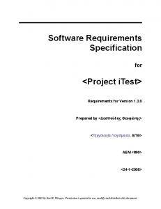
2.5 ARCHITECTURE DESIGN
LOCAL
MACHINE INTERFACE
MAIN PROG
CROSSPONDING COMPONENT
VERIFY ACTION USER
APPLY UPDATE REMOTE
WEB INTERFACE
FEEDBACK
13
2.6 USE CASE MODEL DESCRIPTION
INPUT
SUPPORT
MODIFY COMMANDS
MANAGEMENT AND UPDATE
USER
FEEDBACK
14
2.7 DATA FLOW DIAGRAMS LEVEL 1
CMD VARIFICATION CHECK
MAIN PROGRAM
LEVEL 0
LOCAL
LEVEL 2
CMD SERIAL COM
LEVEL 3
EXECUTE
LEVEL 4
APPLY ACTION
VERIFY ACTION
LEVEL 1’
REMOTE
SERVER
LEVEL 2’
EXECUTE
ESP8266
LEVEL 5
DIGITAL BIT
LEVEL 3’
UPDATE ACTION
FEEDBACK
15
CHAPTER 3
EXTERNAL INTERFACE REQUIREMENTS 3.1 USER INTERFACE No special kind of user interface shell provide in this project. User can interact only through his/her voice. A microphone will be set on the top front part of the body, which I called ‘head’. This portion is chosen because its lot easier to detect user’s voice clearly and much accurately at the top front instead of any other portion. Two speakers on the left and right side of the ‘head’ will also be provided to provide the response/feedback. This will help user to get to know that his/her command has successfully been executed or not. So these two components will interact with the user vice versa. No other interface tool like graphical, LCD, LED screens/display are provided. Below a detailed description of these two UI components are provided:
3.1.1 MICROPHONE Every system requires input to work on. This system needs the same but slightly of different format. Actually, this system is purely voice operational and function on a simple concept; provide speech input and get voice response. But as we know that speech commands are analog in nature and we must first convert them into digital form to do some computation, so we need some sort of equipment/component/device which can do this conversion (the conversion of analog signals to digital signals). As we know that a microphone, colloquially nicknamed mic or mike is a transducer that converts sound into an electrical signal. These electrical signals then feed to the program as input. Now, within the program itself, there are some predefined signals and as soon as the input signal matches the stored signal crossponding action will be taken. So, microphone is the main foundation of the system and it is one of the two user interface unit.
3.1.2 SPEAKERS Two 8 ohm speakers are used to provide the output to the user. These speakers will be placed on the both side of the head (right and left side). These speakers will operate at 0.5 W power and 40mm miniature.
16
3.2 HARDWARE INTERFACE Hardware Interface may include the following main components:
3.2.1 WHEELS There will be four wheels at the bottom of the body to provide the ability to move itself here and there. High density light weight foam wheels will be used.
3.2.2 WHEEL BASE A rectangular flat surfaced box will be used to provide the base to the wheels. Four motors will be mounted on the each corner of base. Wheel base also contains the power supply system inside it, the power to the whole system will be provided from here.
3.2.3 POWER As we have a large number of electronics components (servos, sensors, microcontrollers etc.) the power supply to the system becomes a complex task. The batteries cost too much, which is way greater than the total estimated cost of the project. So In order to make this project work, AC power will be supplied to the system and with the help of certain circuits it will be converted from AC to DC @12V. Now this power will then be feed to the rest of the components. Also the power can be pull up or down crossponding to the component.
3.2.4 SUPPORTING BEAMS 8 supporting beams will be used to provide the support to the structure. 4 beams will be used to support the chest and 4 beams will be used to provide the support to the head. The upper portion of the body from the wheel base will be supported by these beams. Aluminium beam shall be used in the body.
3.2.5 CHEST It is the middle portion of the body and is like a rectangular box inside which equipment like sensors, microcontroller etc. will be mounted. This portion of the body shall be made up of aluminium or plastic and provide a cover to the sensitive electronic components.
3.2.6 HEAD It is the upper portion of the body. It shall be made up of plastic and contains the some electronics components like sound sensor, microphone etc. providing a protective layer to them. It also form a structure of human body. Informally, this portion of the body can rotate itself in the direction of the source of the sound coming from. Servo motor will be used to provide the movement to it.
17
3.2.7 ARMS Two mechanical arms will be mounted on the both side of the chest (right and left) like humans do. One of the two arms will be in the form of a grappler which will be able to grip the real world objects. The specifications of the grappler is that it can rotate at 360° axis and also can move up and down, right and left. Another will be somewhat like a human possess. It will have four fingers and one thumb. This shell be made up polymer and supporting beam of steel or aluminium. Servo motors will be used to provide the necessary movement to the arm. Minimum 8 servo could be used in the build.
3.2.8 SENSORS As we know that a sensor is a device that detects and responds to some type of input from the physical environment. The specific input could be light, heat, motion, moisture, pressure, or any one of a great number of other environmental phenomena. Well, in this project, some sensors will be used which are as follows: 3.2.8.1 IR SENSOR As we know an infrared sensor is an electronic instrument which is used to sense certain characteristics of its surroundings by either emitting and/or detecting infrared radiation. Infrared sensors are also capable of measuring the heat being emitted by an object and detecting motion. Here in this project IR Sensor will be used to measure whether any obstacle is present in the path or not. If present then the machine should have to turn from a safe distance from the obstacle. Informally this sensor will be mounted on the bottom portion of the body i.e. the wheel base so that the working efficiency and functional capacity could be enhanced. 3.2.8.2 SOUND SENSOR Grove - Sound Sensor can detect the sound strength of the environment. The main component of the module is a simple microphone, which is based on the LM358 amplifier and an electret microphone. This module’s output is analog and can be easily sampled. The main use of this sensor is to detect the source of the sound so that it can move itself and could check what’s going on. 3.2.8.3 ULTRASONIC RANGE FINDER An ultrasonic range finder sensor enables a robot to detect obstacles in its path by utilizing the propagation of high-frequency sound waves. The sensor emits a 40 kHz sound wave, which bounces off a reflective surface and returns to the sensor. Then, using the amount of time it takes for the wave to return to the sensor, the distance to the object can be computed. 18
This sensor will be mounted on the top of the body i.e. head so that it could easily detect the obstacles that are out of range of the lower one. 3.2.8.4 TEMPERATURE AND HUMIDITY SENSOR The DHT11 is a basic, ultra-low-cost digital temperature and humidity sensor. It uses a capacitive humidity sensor and a thermistor to measure the surrounding air, and spits out a digital signal on the data pin (no analog input pins needed). It’s fairly simple to use, but requires careful timing to grab data. The only real downside of this sensor is you can only get new data from it once every 2 seconds, so when using our library, sensor readings can be up to 2 seconds old. This sensor will be mounted inside the chest. Main purpose of this sensor is to grab temperature and humidity data from the surrounding. Internal circuitry temperature will be measured by an electrical resistor called thermistor. Actions will be taken according to the temperature measured.
3.2.9 SERVO MOTORS Servo Motors will be used to provide the rotation and movement to the structure. Like arms, wheels, head etc. Basically 8 servos will be used in the right arm which is a general human hand. 5 servos for 5 fingers 1 for wrist, 1 for elbow and 1 for shoulder. Similarly, 6 servos will be used in the left arm which is a grappler.3 servo for grapping module, 1 for wrist, 1 for elbow and 1 for shoulder. 1 servo will be used to provide the rotational mechanism to the head. After all 4 geared dc motor will be used to rotate the wheels and will be responsible for the movement for the entire body structure. These dc motors will be operated @12V.
3.9.10 MOTOR DRIVER A motor driver is a little current amplifier; the function of motor drivers is to take a lowcurrent control signal and then turn it into a higher-current signal that can drive a motor. Since one motor driver can operate two motors so two motor drivers will be enough for four motors. These motor drivers will work under the supervision of microcontroller. They accept the commands direct from the microcontroller and do the crossponding action.
19
3.3 SOFTWARE INTERFACE Since this project uses various components, so in order to control these component some sort of controlling part must exist which will be responsible for the communication and functioning of these components. In our scenario, different program code will handle their crossponding electrical component (I’ll call them slave programs) and they will report to the main program (master program). Hence everything should be smooth and controlled. Below are some tools which will be used to write the code:
3.3.1 Arduino IDE 1.6.12 The Arduino project provides the Arduino integrated development environment (IDE), which is a cross-platform application written in the programming language Java. It originated from the IDE for the languages Processing and Wiring. It was created for people with no profound knowledge of electronics. It includes a code editor with features such as syntax highlighting, brace matching, cutting/pasting text, searching/replacing text and automatic indentation, and provides simple one-click mechanism to compile and upload programs to an Arduino board. A program written with the IDE for Arduino is called a "sketch". Sketches are saved on the development computer as files with the file extension .ino. Arduino Software (IDE) prior to 1.0 saved sketches with the extension .pde. The Arduino IDE supports the languages C and C++ using special rules to organize code. The Arduino IDE supplies a software library called Wiring from the Wiring project, which provides many common input and output procedures. A typical Arduino C/C++ sketch consists of two functions that are compiled and linked with a program stub main() into an executable cyclic executive program: setup(): this function is called once when a sketch starts after power-up or reset. It is used to initialize variables, pin modes, start using libraries, etc. loop(): after setup() is called, this function is called repeatedly until the board powers off. It actively controls the Arduino board and allows the program to change or respond. After compiling and linking with the GNU toolchain, also included with the IDE distribution, the Arduino IDE employs the program avrdude to convert the executable code into a text file in hexadecimal coding that is loaded into the Arduino board by a loader program in the board's firmware. So, these are the software interfaces that are used in the development of the project. The application will be created using a development kit which provides an environment to create android applications. Informally, android studio is used for this reason. This IDE is very simple and easy to use. 20
So in order to install this IDE two other software will be required, which are Android SDK and JDK. After installing both these kits we will be ready to install the IDE. After installing, we will create the required application. The Arduino IDE will be used to program the Module. This is also very simple and easy to use IDE and support C/C++ rules. Some more rules are added to make it more effective and user oriented. This will help to program the module. This will be used to program the Arduino microcontroller and ESP8266 chip.
3.3.2 WINDOWS 10 IOT CORE Windows 10 IoT Core is a version of Windows 10 that is optimized for smaller devices with or without a display, and that runs on the Raspberry Pi 2 and 3, Arrow Dragon Board 410c & Minnow Board MAX. Windows 10 IoT Core utilizes the rich, extensible Universal Windows Platform (UWP) API for building great solutions. This will be installed on raspberry pi to run our window application. The main program will run within this system and control other slave programs. 3.3.3 IIS IIS is a web server which is used to run web applications locally as well as globally. The web application will be developed using MS ASP.net. The main use of this service is to run the web application which can get the request from the ESP8266 address and also send the request to the same. This will let us control the system anywhere in the world.
The flow control is described below:
User must visit the specified web site. UI is fairly easy to use. Various components are provided in order to control the system. When user generates a request, a connection will be established between the web application and the web address provided by the ESP8266 module. The request will then send to the specified web address. Necessary actions will be taken crossponding to the request and those actions will then transfer to the hardware module. That hardware module (ESP8266) then sends binary digit (either 0 or 1) to the controller. Microcontroller then takes action crossponding to the received digit. Similar happens when feedback is required to the end node of the system.
Thus in this way, user would be able to access and control his/her assistant anywhere, anytime!
21