Software Stability: Timeless Architectures and System of Patterns - ProceedingsAICCSA 2005 Workshop # 3 http://www.engr.sjsu.edu/~fayad/workshops/AICCSA-05
or http://www.activeframworks.com/publications/workshops/AICCSA-05
In Association with the 3 ACS/IEEE International Conference on Computer Systems and Applications rd
AICCSA05
American University in Cairo (AUC), Cairo, Egypt January 3-6, 2005 http://engr.smu.edu/cse/AICCSA-05/
Mohamed E. Fayad, PhD, San José State University, U.S.A. Haitham S. Hamza, University of Nebraska-Lincoln, U.S.A
University of Nebraska-Lincoln Computer Science & Engineering Department Technical Report No. 04-12-03 December 2004
Preface This proceedings contains the contributions to the 1st Workshop on Software Stability: Timeless Architectures and Systems of Patterns, held in conjunction with the 3rd ACS/IEEE International Conference on Computer Systems and Applications, American University in Cairo, Cairo, Egypt January 3, 2005. The increasing complexity of software systems coupled with the time-to-market constraints and condensed development budgets all have imposed a real challenge on the future of software development. It becomes a matter of survivability for a business to be able to deliver a highquality and cost-effective software product in a timely manner. This goal can be greatly precluded by the rapid advances in technology as well as the increasing pace of changes in market needs and customer requirements. Such changes while cannot be avoided; their impact on the system development should be alleviated. A system that requires a major redesign effort in order to adapt to new requirements and emerging technologies is considered to be unstable. A stable system, on the other hand, can handle changes to the system with minimal cost by avoiding unnecessarily changes when redesigning the system. However, developing systems that can evolve gracefully to accommodate necessarily changes without inducing unnecessarily cost is still a challenge in software community. The motivation of this workshop is to investigate both theoretical and practical aspects of accomplishing stability in the different levels of software development. In this workshop, we have 11 original contributions that highlight the state-of-the-art and practice in developing stable software systems. Contributions span the different phases of software development from requirements and business domain analysis to design and deployment. Some papers address the theoretical aspects of developing stable systems, while some contributions investigate the development of stable patterns, and the use of patterns to architect stable systems. The web page of the workshop may be found at URL: http://www.engr.sjsu.edu/~fayad/workshops/AICCSA05 http://www.activeframworks.com/publications/workshops/AICCSA05 We would like to thank the conference organizers for their support as well as the authors and participants for their high-quality submissions and engaged contributions during the workshop.
Sincerely, The Workshop Organizers Mohamed E. Fayad and Haitham S. Hamza
II
Organization
Dr. Mohamed E. Fayad –Chair Professor of Computer Engineering Computer Engineering Dept., College of Engineering San José State University One Washington Square, San José, CA 95192-0180 Ph: (408) 924-7364, Fax: (408) 924-4153 E-mail:
[email protected] http://www.engr.sjsu.edu/fayad
MOHAMED E. FAYAD is a Full Professor of Computer Engineering at San Jose State University. He was a J.D. Edwards Professor, Computer Science & Engineering, at the University of Nebraska, Lincoln and an associate professor at the computer science and computer engineering faculty at the University of Nevada, from 1995 - 1999. He has 15+ years of industrial experience. He has been actively involved in over 60 Object-Oriented projects in several companies using Shlaer-Mellor, Colbert, OMT, Use Case Approach, UML, Design Patterns, Frameworks, Software Process Improvement, Systems & Software Engineering, Internet and Web Applications using Java, OO Distributed Computing using CORBA, and others. Dr. Fayad is a Senior Member of the IEEE, a Senior Member of the IEEE Computer Society, a Member of the ACM, an IEEE Distinguished Speaker, an Associate Editor, Editorial Advisor, and a Columnist for The Communications of the ACM and his column is Thinking Objectively, and a columnist for Al-Ahram Egyptians Newspaper (12 million subscribers), an Editor-In-Chief for IEEE Computer Society Press Computer Science and Engineering Practice Press (1995-1997), IASTED Technical Committee member on Software Engineering (2001-2004), and a general chair of IEEE/Arab Computer Society International Conference on Computer Systems and Applications (AICCSA 2001), Beirut, Lebanon, June 26-29, 2001 Dr. Fayad was a guest editor on nine theme issues: CACM's OO Experiences, Oct. 1995, IEEE Computer's Managing OO Software Development Projects, Sept. 1996, CACM's Software Patterns, Oct. 1996, CACM's OO Application Frameworks, Oct. 1997, ACM Computing Surveys – OO Application Frameworks, March 2000, IEEE Software - Software Engineering in-the-small, Sept./Oct. 2000, and International Journal on Software Practice and Experiences, July 2001, IEEE Transaction on Robotics and Automation -- Object-Oriented Methods for Distributed Control Architecture, October 2002, and Annals of Software Engineering Journal – OO Web-Based Software Engineering, October 2002. He has published articles in many journals and magazines, such as IEEE Software, IEEE Computer, JOOP, ACM Computing Surveys and CACM on OO software engineering methods, experiences, aspect-oriented programming, internet & web applications, enterprise and application frameworks, design patterns, and management. He has given tutorials and seminars on OO Technologies and Experiences at many conferences and he has presented various seminars in several countries: Hong Kong (April 96), Canada (10 times), Bahrain, Saudi Arabia, Egypt (12 times), Portugal (Oct. 96, July 99), Finland (July 99), Mexico (Oct. 98), Argentina (3 times), Chile (00), Peru (02), and Spain (02). Dr. Fayad received an MS and a Ph.D. in computer science, from the University of Minnesota at Minneapolis. His research topic was OO Software Engineering: Problems & Perspectives. He is the
III
lead author of several Wiley books: Transition to OO Software Development, August 1998, Building Application Frameworks, Sept., 1999, Implementing Application Frameworks, Sept., 1999, DomainSpecific Application Frameworks, Oct., 1999, and a new book in Progress: Stable Software Patterns: Analysis, Design, and Applications. Haitham S. Hamza – Co-Chair Computer Science & Engineering Dept University of Nebraska, Lincoln 256 Avery Hall, P.O. Box 880115, Lincoln, NE 68588-0115 Ph: (402) 472-3485 E-mail:
[email protected] HAITHAM S. HAMZA received an MS in computer science, from the University of Nebraska-Lincoln, August 2002 and an MS in Electronics & Communication Engineering from Cairo University, December 2000. His research topic was A Foundation For Building Stable Analysis Patterns. He is a co- author of a new book on “Stable Software Patterns” with Dr. M.E. Fayad and Dr. M. Cline, Wiley 2005. He has published articles in many conferences and magazines, such as PLoP, ECOOP and CACM on stable model-based architectures, design patterns, stable analysis and design patterns, software stability.
IV
Table of Contents Architecture Pattern for a Generic Explanation Component...………………...………….........................1
Susanne Jäger (Universität Klagenfurt, Austria) and Roland T. Mittermeir (Universität Klagenfurt, Austria ) Stability of Reusable Learning Objects.....................................................................................................6 Imran A. Zualkernan (University of Nebraska-Lincoln, UAE), Reverse Engineering of Framework Design using a Meta-Patterns-based Approach..……..............10
Nuno Flores (Porto, Portugal) and Ademar Aguiar (Porto, Portugal) Making Efficient Logging a Common Practice in Software Development………................................17
Osama M. Khaled (American University in Cairo, Egypt) and Hoda M. Hosny (American University in Cairo, Egypt) A Novel Approach for Managing Business Rules Evolution and Reuse in Business Architectures.…....………………………………………………………………………....…...........22
Haitham Hamza (University of Nebraska-Lincoln, USA), Mohamed E. Fayad (San José State University, USA) Architectural Modelling to Understand System Evolution…..…………………………..........................29
Galal H. Galal-Edeen (Cairo University, Egypt) Software Stability : A Rewriting Formal Specification Approach………………………...……...............38 Mohamed L. Rebaiaia (University of Batna, Algeria ) Planning Stable Software Applications using Goal Driven Requirements Analysis..........................46 Islam A. M. El-Maddah (Ain Shams University, Egypt) Performance Modeling and Analysis of Object Oriented Distributed Software Systems: A Necessary Step Toward Software Performance Stability………........................................................52 Reda Ammar (Univ. of Connecticut , USA), Amal Abdel-raouf (Univ. of Connecticut , USA) and Tahany A. Fergany (Univ. of New Haven , USA) A Stable Architectural Model for Networks with Trajectory-Dependent QoS………….......................57
Ahmed M. Mahdy (University of Nebraska-Lincoln, USA) and Mohamed E. Fayad (San José State University, USA) Monitoring and Reuse Software Patterns Analysis in Maude…...…………..........................................61 Mohamed L. Rebaiaia (University of Batna, Algeria )
V
Architecture Pattern for a Generic Explanation Component Susanne Jäger, Roland T. Mittermeir Institut für Informatik-Systeme Universität Klagenfurt AUSTRIA {susi, roland}@isys.uni-klu.ac.at Abstract The paper reports on the architecture of an explanation component for an educational simulation system. This architecture assures tolerance against modifications of the model driving the simulation. Architectural stability is achieved by extending the principle of state-dismemberment to aspects of application processing. Querying aspects of the model and relating it to aspects of the state of the simulation yields information to construct another query into model aspects and state aspects. Relating the respective information allows providing users with focused feedback, while the software driving this process has just to follow general principles.
1. Motivation The architecture described in this paper has been developed for AMEISE1, a system that allows students to practice managing software development projects [1, 2]. AMEISE consists of a generic simulator, SESAM [3], which has been wrapped and extended by various tools to allow instructors to tune the difficulty of a simulation task. Such extensions comprise a consultant, which can be asked how to proceed at certain critical points, and a friendly peer which intervenes when noticing that students are progressing into a fundamentally wrong direction. Architecture, in general, defines the evolution interface of systems. Systems are subject to evolution drivers of different sort [4]. A standard strategy to deal with unforeseen change is modularity. In specific situations, though, more powerful approaches can be used. Treating software as data [5] is one of them. At the expense of run-time efficiency, it allows to hard-code only the most
fundamental parts of a system in the classical way. This yields a generic framework which is completed to an executable system by parameters, read as data and properly interpreted. Shaw has formalized this under the term interpreter pattern [6]. In SESAM this principle is followed as so far as the system consists of a simulator which loads the model of a particular software development scenario. This scenario is expressed in a rule-based language. It describes developers and their qualifications to produce various artefacts by pursuing specific activities. Modelled are: the time needed to produce a specification or to perform a test; the budget consumed during these activities; errors introduced, detected, or corrected during an activity. Performance depends on the task, the person’s qualification, and the quality of the base used for performing this task. In SESAM, the results of such a simulation need to be interpreted by the instructor. To relieve instructors from some of the time consuming interpretation of results and to give students intermediate feedback and support, AMEISE has to interpret final as well as intermediate results of the simulation. This requirement motivated us to extend the simulation system towards an expert system with an explanation component. The challenge of this requirement is that such an interpretation has not only to be aware of the model but also of the interactions between the model and the user’s state space. Both are highly complex if the task is to realistically describe software development. A further challenge is to make this component resistant against future changes of the model. In the remainder of this paper the interpreter pattern is briefly reviewed. It is shown how this pattern can be applied to the task at hand. Then, the specific architecture, which has to cope with rules of different complexity, is described. To make this approach even more change resistant, a special rule insertion tool has been developed.
1
) Development of AMEISE, A Media Education Initiative for Software Engineering, has been supported by bm:bwk, the Austrian Federal Ministry of Science, under grant NML-1/77 .
1
2. Interpreter Pattern, interpreted
3. Prototypical Realization of this Strategy
2.1. Point of Departure
3.1. Principles of Evaluation Rules
The key principle behind the interpreter pattern [6] is to split the semantics of a software solution into domain specific problem semantics and system specific solution semantics. Providing this separation on the same level of abstraction will lead to a conventional modularised system. With the interpreter pattern, the solution is raised to a higher, more abstract level. The resulting generic solution is parameterised by an interpretable description of the specific category of the problem domain for which the fully developed system is finally to be used. In a nutshell one might think about a Universal Turing Machine with the UTM being the interpreter, the domain description being the program for the UTM, and the actual user data and system-state being whatever rests on UTM’s tape. The UTM, of course, is an extreme case. When developing stable application systems, the designer’s qualifications will ensure that a good trade-off is found between the complexity of the actual interpreter and the one of the domain description. A balanced solution will result in a stable situation, involving as little maintenance effort as possible.
The information needed to analyse a project’s progress is stored in a database. In SESAM, knowledge how to analyse this data rests with the instructor. Observing an experienced instructor’s reasoning and interpretation led to a list of assessment criteria [7]. “Project cost” is an important criterion which is easy to analyse. It centres on the question “Has the student exceeded the limit of € 225.000 for project cost?” The answer will be either YES or NO. Though simple, this example shows the recurring elements of AMEISE evaluation rules. Every assessment criterion consists of one or more attribute(s) to be analysed and for each attribute an associated reference point. Relating the reference point of an attribute to the respective state of the simulation by a comparison operator yields either YES or NO as intermediate result. According to this answer, different evaluation texts are emitted. Therefore, every assessment criterion is represented as a set of so-called specific aids. Each specific aid handles one of these cases. E.g., the assessment criterion “project cost” can be analysed by answering the question “Has the player exceeded the project costs limit of € 225.000?”. To account for each possible answer, it is represented by two different specific aids. 1) “total_cost is greater than € 225.000”, and 2) “total_cost is less or equal € 225.000”. Unfortunately, only a few assessment criteria can be described in this simple form. For more complex criteria elementary rules must be combined to chains of rules by logical operators. E.g., “AFP_ for_the_specification > 199 AND errors_in_specification < 30” should yield “Your specification is complete and quite correct!”. An example dealing with task assignment to developers is “author_specification == Diana AND qualified_for_writing_specifications == Diana”. It might yield “Diana was the right choice for writing the specification.” This shows that it is also possible to use text as reference point. Each chain of rules consists of a set of single rules which are called instances. For successful execution of the whole rule, the order in which terms representing elementary rule-instances are combined must be retained. The evaluation of an assessment criterion is carried out by a rule interpreter. Its task is to get the relevant information (i.e., all specific aids which belong to the selected assessment criterion) from the database and to formulate an automatically generated SQL-query which finally yields the explanations to be given to the student as shown in Fig. 1. All project attributes relevant for the
2.2. Recursive Use With explanation components as needed in AMEISE or in similar complex reasoning systems, direct use of the interpreter pattern would be too weak. Both, the program to be simulated as well as the (intermediate) state of a simulation would be too complex to allow a clear decision where to separate between the general solution (interpreter), problem description (program) and data (user state). To be efficient, the user state has to be addressed repeatedly and in a highly focused manner. As additional requirement, the AMEISE solution should be robust against changes of the model. To cope with this, the interpreter pattern is applied recursively, till a message can be constructed which can be finally emitted to the user. As described in the following section, this requires repeatedly accessing the state space and comparing the results obtained with partial descriptions derived from the model. Based on the results of this comparison and its relation to parameters of the target space (also depending on the particular model used in the simulation), either another query is formulated against the state space, the model description, and result description, or a message to the HCI-component is emitted.
2
evaluation of the project are stored in the database and can be obtained by an SQL-statement which gets the value of an attribute for a given simulation run from the database.
TRUE. To execute a specific aid implies the rule interpreter to execute an SQL-statement to load the actual value of the attribute “cost” from the database. Assuming the actual attribute value is 216.000, it combines this value, the operator (assume “>”) and the reference point (allocated budget of € 225.000) to a new predicate. In the example, this predicate is: “216.000 > 225.000”. Its evaluation yields FALSE. Thus, the rule interpreter aborts evaluation of this alternative and tries the next specific aid. In this case, this will be composed to the predicate “216.000 225.000 “You have exceeded the limit!”
specific aid 2 cost R1= negotiation. items AnyAgreement.items
1..*
AnyAccount
=
LineItem
1 has 1..*
AnyEntry 1..*
AnyLog
1..* has 1..*
Receipt
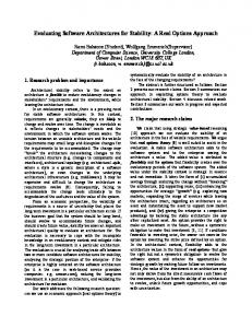
Figure 5. Renting business architecture annotated with different types of rules.
Organization Representative
Renting
1..* desires
1..*
AnyParty
Negotiation
Renter
signs
initiates results in
AnyAgreement 1..*
> R3= Renter.ID = {OK}
1..* specifies
opens
1..*
LineItem
1
pays
Car
AnyAccount receives has 1 1..*
> R4= Receipt.ammount = Payment.ammount
AnyEntry 1..*
AnyLog
1..*
1..*
Receipt
Payment
has
Process rule
Check
Cash
Credit Card
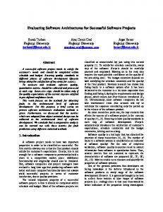
Figure 6. Car renting business architecture annotated with different types of rules.
27
28
Architectural Modelling to Understand System Evolution Galal H. Galal-Edeen Faculty of Computers and Informatics, Cairo University, Orman, Giza 12613 - Egypt
Email:
[email protected]
Abstract This report outlines the research carried out with the support of a grant by the EPSRC (Engineering and Physical Sciences Research Council) of England, United Kingdom, under the Systems Integration initiative within EPSRC. We have analysed a problem domain using a qualitative research methodology to model its main architectural features. Our model formed an input to an associated EPSRC grant under the same initiative. Links between the results of systematic qualitative analysis and architectural software analysis have been shown, demonstrating the feasibility of further research into the idea of architectonic isomorphisms between a problem domain and the adaptability of associated software artefacts. We point out the technical developments resulting from this investigation, and point a way forward.
Background/ Context The issues for devising software and systems architecture that are adaptable in the long term has come to the fore of the interests of the software and information systems communities [11]. A main issue is how to bring an understanding of some problem domain to bear on the technical architecture in a way that fosters the emergence of desired non-functional properties such as adaptability and robustness. This grant together with the associated grant GR/R11919/01 (at the University of Portsmouth) formed an integrated programme of research that sought to explore the relationships between a software artefact and the original problem domain 3 that required it in the first place. Our research collaborators in UoP concentrated on the analysis and modelling of number of extant software artefacts, and we concentrated on the exploration, modelling and analysis of one of the
relevant host domains. Our working hypothesis was that a relationship, at the architectural level4, could eventually be discerned between the problem domain and its related software artefact. The nature of the architectural link is what we previously used the concept of Architectonic isomorphism to characterise [1]. The use of the term architectonic to describe a certain architectural view of software systems [6, 8, 10, 16] is based on a certain use in architecture [4] which refers to the differentiation of constructional elements according to their relative stability. This view is also borne out by the concept of shearing layers [2], which relates the adaptability of a building to the degree to which layers of its constructional elements are de-coupled in a way that accommodates, in relative terms, new or unforeseen requirements. The reasoning being that constructional layers can slip past each other: changes to one layer do not necessitate changes to others. Note here that the low coupling is not at the level of individual constructional elements (such as bricks for instance), rather, the decoupling referred to is at the level of categories of such elements. The constructional elements are categorised according to the degree of susceptibility to, or speed of, change that they share. Figure 1 below illustrates this view.
3
We use the term “Domain” in the sense that features in Jackson’s usage (Jackson 2001), to refer to the specific application domain, rather than a generic activity domain such as air traffic control.
4
We strongly demarcate the architectural level from the structural one. See (Galal 1998) for an elaboration.
29
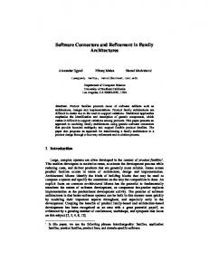
Figure 1. Shearing Layers of Change (Courtesy of Phoenix Illustrated)
Since this view is fundamentally normative, i.e. it is based on a study of the types of changes that typically affect buildings, we must ground any such analysis in the cultures that give rise to any specific architectonic profile. The fundamental question of this research is whether revealing the relative embeddedness of domain concepts can help in structuring software (or indeed another technical artefact) in a way that makes it more adaptable and in tune with the dynamics of the change profiles of the original problem domain.
Investigating architectonic isomorphisms
D a t a co lle ct io n D A T A P R E P A R A T I O N
D a t a s t or a g e
O p e n c o d in g (s e le c t a n d n a m e c a t e g o r ie s )
I N I T I A L A N A L Y S I S
C O R E A N A L Y S I S
S e le c t a n d e la b o r a t e c o r e ca t e g or y (S e le c t iv e c o d in g )
R e la t e c a t e g o r ie s (A x ia l c o d in g )
2.1 Applying GSEM to modelling the problem domain We applied our qualitative analysis-based framework, the Grounded Systems Engineering Methodology (GSEM)[8, 7] to try to identify the architectonic profile of the problem domain for which certain software artefacts have been developed. One of the fundamental ingredients of GSEM is the rigorous qualitative analysis of a problem domain, typically using the Grounded Theory method from the social sciences [18]. We have built GSEM around procedures to operationalise Grounded Theory to describe a problem domain, define its core requirements and arrive at a system architectural design [9]. Figure 2 below describes the core procedure upon which GSEM domain analysis and modelling was based:
D o m a in
t h e o r ie s
O b je c t iv e s
O U T C O M E S
R is k s C o n s t r a in t s S t r a t e g ic a n d I n t e r p r e t iv e S ce n a r io s G r a p h ics M o d e ls
Figure 2. Core steps in Grounded Theory analysis (adapted from [17].
GSEM increases the fidelity of domain analysis and structuring activity by bringing the subjectivity of the analyst under greater discipline, through applying the principle of giving rigorous consideration to the data, all the data and nothing but the data. The selection process that is a fundamental part of any analysis activity is brought into the open and under improved visibility and control. The process of exploring, understanding and modeling a problem domain can be a lengthy process and so we chose just one example, SUEZ, to investigate in detail. SUEZ was written for Ship Analytics to model sea fluid cargo dynamics and is the largest and most complex project of the four Fortran programs (which were analysed by our research collaborators in UoP). It is also the newest of the ones provided, written around 1997.
2.2 A GSEM Analysis of the domain. In the course of investigating the Ship Analytics domain, we interviewed a number of key individuals (domain experts, software architects, chief programmers and technical managers) who knew about the domain, its environment and history. Table 1 gives a summary of the main persons interviewed.
30
Name Edgar Ernstbrunner
Function Organisation Main programmer Ship Analytics Warsash Lecturer Alan Whitcher (Petrochemical Division) Warsash Mike Barnet Lecturer (Petrochemical Division) Ray Gillett Program Manager Ship Analytics George Angus Ex-Warsash Warsash Director Mike Turner Ex-Ferranti project Ferranti manager Jack Ponton Prof. Of Chemical Edinburgh Engineering Table 1. Roles, function and affiliation of persons interviewed
After approximately seven iterations of the analysis, supported by the Atlas.ti qualitative analysis software, we reached the model of the domain illustrated in Figure 3.
2.3 Matching architectonic 5 levels Our initial analysis is simply numeric, based on counts of the concept occurrences and similar ones in the software artefact. The early stages of the analysis revealed the following domain concepts in order of relative weight or dominance: • Tanker • Cargo • Plan • Compound • Risk The frequency order of the two top concepts (Tanker and Cargo) occupied high relative positions that corresponded to the relative size of the keystone groups revealed by our colleagues in UoP. Further analysis of both the domain (this time focusing on the density of structural associations) and the related software confirmed this observation as explained below. We provided our research collaborators at UoP (Grant GR/R11919/01), with a detailed analysis of one of the projects’ problem domains. This analysis was provided in the form of a diagram with various relationships between the conceptual units revealed, along with numerical counts expressing the density of inter-associations between concepts. Our research collaborators normalised and reduced the model into a form that was more comparable with the results of their analysis. The result of this normalisation process is shown in Figure 4.
Figure 3 (A8 Overview): A qualitative model of the ship simulation domain.
To render the model in Figure 3 above comparable to the ones our colleagues in Portsmouth University have produced for the software, it was necessary to normalise it. One of the key advances of this project is the way in which the qualitative model has had to be normalised to render it comparable to the outcome of the keystone analyses carried out at Portsmouth on the corresponding software.
Figure 4. Normalised graphs of problem domain concepts and relationships.
The architectonic structure of the associated software artefact extracted by the analysis tool is shown in Figure 5, which shows four major keystone groups at the root context of the artefact. Relating these groups to the structure as given in Figure 4 (resulting from the problem domain analysis) reveals immediately a match 5
Architectonics is used to indicate the differentiation into levels of flexibility or likelihood of change. See (Galal & Paul 1999) .
31
between the two largest (or heaviest) groups with specific concepts in Figure 5 as indicated by the wide arrows in both figures. The other groups in the root context of the context tree are also related to the artefact domain, but with a lower degree of substantiality to the domain. The significance of the isomorphic match can best be explained in terms of the propagation of behavioural change. This can only travel up an arrow, towards the dependent and never down and as a result of this, knowing the conceptual match between both the problem domain and artefact domain indicates which changes in the problem domain could be mirrored to the artefact domain. This is a significant result from the point of view of the designer who would need to determine the base architectural layer for the software artefact in a way that fosters greater adaptability.
Figure 5. Pruned context tree of related software artifact.
However, the exact nature of these interface-links (wide arrows in Figures 4&5), their mechanisms and what kind of influence they have on a given variety of desired changes are still unknown. This, we believe, needs analyses of various snapshots for the same software artefact through a few adaptation cycles. It is unlikely there will be just a single mechanism that applies to all cases. Since the isomorphic match is only between few (but relatively more significant) concepts, the original idea of a full match between the program structure and problem domain was evolved into the idea of an interface between the two. This interface has the unique property that it resembles parts of the architecture of both the artefact- and problem-domain. At this interface level, we expect a good program to have the same architectonic levels as the problem domain and vice versa. Indications for this can be seen in Figure 4 and Figure 5 where the concepts of the isomorphic groups in the artefact match
(i.e., are semantically close to) concepts in the problem domain.
2.4 Applying configurational space analysis techniques to conceptual models. To get to the architectonic profile of the domain, we conducted further analyses in which we used methods and tools from the set of spatial analysis techniques known as Space Syntax. Space Syntax refers to a collection of inter-related representational tools and analytic techniques, supported by software tools and by a philosophy as to how spatial configurations operate through influencing societies and vice versa [12, 13, 14]. Space syntax has been successfully used to explain the emergence of a number of pedestrian and land use phenomena in the built environment, such as footfall, crime and other anti-social behaviour as well as the location of retail activity. The philosophical foundation of Space Syntax is that of Structuralism [3] and its fundamental principle that it is the relationships between elements of the language that constitute the meaning of the signs that it contains. We consider that the same principle applies when reasoning about problem domains too, thus we can base domain modelling on similar structural principles. Reflecting the resulting structural models into the software or other technical artefact has always been one of the aims of software and systems engineering activities. We add to this that adaptable artefacts need to reflect domain structures that address adaptability (to us this means likelihood of change) as a core value. However, to us the nature of language in general, and by implication languages to describe specific domains in particular, also embodies architectonic principles. This is the sense that there are concepts that are core to a domain in that they have a high impact on rendering it cognisable. Following Frampton’s [4] use of the term stereotomic, we say that such core concepts play a stereotomic (or heavy, or solid) role in constituting a given domain. Our analyses show that both the problem domain architecture and artefact architecture will have concepts such as Tanker (or Vessel) and Cargo as core, both are stereotomic concepts towards which the model will tend to gravitate. We used configurational analysis to get to the conceptual elements that more fundamental to understanding the domain: these are concepts that are simply the most referenced by other concepts, and thus they provide a higher relative privilege in understanding the domain in question. The results of configuration analysis can be depicted as a serious of coloured lines (Figures 6&7). Each line represents a concept uncovered through the qualitative analysis conducted. The colours represent the degree of integration that the line has within the constellation of concepts connected to it. The
32
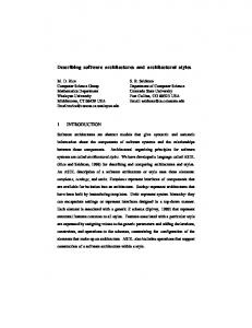
closer the colour is to red, the more integrated it is; red being the most integrated, relative to other lines. Figure 6 shows the results of carrying out configuration analysis on the normalised conceptual diagram of the problem domain. The corresponding integration values are given in Table 2. Figure 7 shows the results of carrying out configuration analysis on the software artefact related to the same domain, whilst the corresponding integration values are shown in Table 3. In both figures (6&7) the core concepts of the domain, these that closer to the colour red (or the darkest shade on a grey scale print), have a strong integrative influence on the remaining concepts within the same analysis. The closeness of the various colours to red is borne out by the values in tables 2 & 3. Highly integrative concepts are those that are more fundamental to understanding the domain; in other words these are more critical to understanding (or interpreting) the constellation of the remaining concepts in the qualitative domain model that we offer. This is a novel application of the concept of integration from urban morphology [12] to domain and software analyses. In both figures, it can be seen that the most integrated lines6 have remained more or less the same (we ignore the vertical red line (no. 1) in Figure 7 since it simply stands for the root module for the whole diagram, a purely synthetic and artefact-bound concept). The line no. 1, representing the “Program” node is actually not the most integrating one, but the line representing the “Vessel” concept is. Table 3 gives the global integration measures for the context tree diagram of the software. Line identification numbers are printed next to each line to facilitate linking them to the Line ID columns in the associated tables. Dark arrows point to the “heaviest” concepts.
1.2242
4 0.4840
10
7
Measure =2
1 3 2 5
9
6 11
8
12 13
14
Figure 6. Integration (Rad n) map of the normalised domain model7
Line ID Order Concept name
Integ Rad=n
6
1
TANKER
1.2241853
8
2
CARGO
1.0953236
5
3
TANKER_SEA
0.9910071
7
4
CARGO_ENVIRONMENT
0.9048326 0.9048326
11
5
tanker_equipment
2
6
SEA
0.832446
4
7
ENVIRONMENT (sea, air, temp)
0.7707833
9
8
cargo_type
0.7176259
12
9
e.f.t. [equipment flow type]
0.6713274
3
10
ENVIRONMENT (natural & social) 0.5946043
1
11
AIR
10
12
Cargo Processing Types
0.5624635 0.507589
13
13
equipment
0.4839802
14
14
process_equip
0.4839802
Table 2. Global Integration (Rad n) values for the problem domain model
7
6
In urban morphology, the most integrated lines are the most key lines to navigating and understanding the urban grid.
Rad n abbreviates Radius n, or Global Integration, in which the integration of a line is calculated with respect to all other lines in the system by travelling to all other lines in every possible direction. Integration can be also calculated for various radii. For example Radius 3 is calculated by travelling up to only three lines away from each line in every possible direction.
33
1.5888
weight that was mirrored in the software artefact. But we note that the said artefact has been subject to adaptation and evolution for some time. In a sense we have been looking into the structure that resulted from the artefact’s adaptation to accommodate evolving requirements. This work reveals the feasibility of the qualitative/ structural analysis of the domain with the aim of relating it to a corresponding technical artefact.
2 3
0.5202 Measure =2
9 13 8
11 16 18 15
Difficulties encountered
20
17
21 22 23 19
24
25 26
Figure 7. Global Integration (Rad n) map of the context tree diagram of the SUEZ software
Line ID
Order
5 1
Concept name
Integ Rad=n
1
SUEZMAIN:VESSLS
1.5887512
2
PROGRAM
1.5072768
19
3
SUEZCRG:VESCRG
1.250719
4
4
SUEZMAIN:FLOWST
1.1526234
3
5
RUNSIM:STARTUP
0.9963355
14
6
SUEZSTAB:STABILTY
0.9636687
15
7
SUEZIG:VESIG
0.9636687
16
8
SUEZGMONF:GSDETFLO
0.9636687
17
9
SUEZMAIN:FLONET
0.9636687
18
10
SUEZSTNK:GENTNK
0.9636687
2
11
SUEZINCTK:INITIAL
0.9330761
23
12
SUEZTANK:SUEZTNK
0.9043661
20
13
SUEZCONN:MANPEXT
0.8773701
10
14
SUEZSTEAM:FLOSTEAM
0.8052574
12
15
SUEZCRG:FLOCRG
0.8052574
8
16
SUEZIG:FLOIG
0.7837839
9
17
SUEZCONN:CONMANIF
0.7837839
6
18
INSUEZTAB:INIPROP
0.7257259
24
19
SUEZTANK:OILTANK
0.691574
21
20
SUEZCONN:CONNEXTP
0.6604921
11
21
SUEZSTEAM:STHEAT
0.6060184
13
22
SUEZCPMP:PUMPEDCT
0.6060184
7
23
INSUEZTAB:INCOEF
0.5598457
25
24
SUEZTLIQ:OILTLIQ
0.5393009
26
25
SUEZTIO:OILTIO
0.5393009
22
26
SUEZEXTP:CHKEXTP
0.5202106
Table 3. Global Integration (Rad n) values for the software artifact context tree.
The core elements of the domain have evidently been propagated into the technical artefact, and more importantly, remained recognisable after the software has undergone various adaptations, and with a relative
The original plan allocates three months to the work involving using GSEM to analyse the domain. The work involved considerably longer due to the following factors: a) A considerable period of training and orientation for the research fellow appointed to carry out the qualitative domain analysis, both in architectural thinking in general and the particulars of Grounded Theory analysis on which GSEM is based, was needed. This consumed a substantial amount of time and leading to the interview transcription and analysis period taking eight months instead of the originally anticipated three. On reflection, three months would have probably been too short anyway and six months would have been a more realistic estimate to cater for the difficulty of actually carrying out interviews and pre-processing their content. b) Although the collaborators were willing to provide access, actually setting up access for the necessary interviews took a considerable time (about three additional months) to discuss the nature of data needed and to sign the necessary confidentiality agreements in a form that satisfied the organisation that owned the software and employed the domain experts. Interviews with the domain experts started only after these preparations were complete.
Research impact This research project was for a one-year feasibility study into the extent to which the concepts of architectonics and architectonic matches apply to problem domains and a corresponding software artefact; investigating the existence of a link between what we termed “domain architectonics” and “software architectonics”. This grant, along with the associated grant GR/R11919/01, held by our research collaborators at the University of Portsmouth developed research tools and concepts that can be applied to revealing the core architectonic isomorphisms between artefacts and corresponding domains. The two grants, taken together, have revealed
34
the feasibility of investigating the concept of architectonic correspondences between domains and artefacts. A set of appropriate analytic tools have also been developed, and a development cycle that clearly links the domain investigation and software architecting cycles has been proposed (see the final report for the linked grant GR/R11919/01 at UoP). We have established that further research into this area is both feasible and promising. We outline this in the further research section below.
Modelling to Understand System Evolution European Conference on Information Systems, 2001, June 27-29, Bled, Slovenia.\ 2. Brand, S. (1994). How buildings learn: What happens after they're built. London, Phoenix Illustrated. 3. Sassure, F. (1966 (1915)). Course in General Lingusitics, McGraw Hill. 4. Frampton, K. and J. e. Cava (1995). Studies in Tectonic Culture - The Poetics of Construction in Nineteenth and Twentieth Century Architecture. Cambridge, Massachusetts, The MIT Press. 5. Galal, G. H. (1998). Software architecting: from Further research or dissemination activities requirements to building blocks within an To build on the work already done, we believe that architectural style. 12th European Conference on further work is needed in the following areas: Object-Oriented Programming: ECOOP'98, 2024 July , 1998. Workshop W2: Techniques, a) Investigate successive versions of the same Tools and Formalisms for capturing and software, preferably using additional examples assessing Architectural Quality in Objectfrom other domains, in various stages of its Oriented Software, Brussels, Belgium, evolution, to see the degree of stability of the http://www.emn.fr/borne/. architectonic layers that we predict would be 6. Galal, G. H. (1999). “On the Architectonics of stable. The crystallisation of these notions would Requirements.” Requirements Engineering aid designers in designing software (or other) Journal 4(3): 165-167. artefacts that reflect the architectonic profile of 7. Galal, G. H. (2001). “From Contexts to Constructs: original problem domains, into software and the use of Grounded Theory in Operationalising systems artefacts. Contingent Process Models.” European Journal b) Developing measures of software artefact of Information Systems 10(1): 2-14. adaptability that can be compared to degrees of 8. Galal, G. H. and R. J. Paul (1999). “A Qualitative architectonic matches. If we are able to show that Scenario Approach to Managing Evolving flexible software has a high degree of architectural Requirements.” Requirements Engineering correspondence to a model of the domain, then this Journal 4: 92-102. is again will prove a substantial aid in designing 9. Galal, G. H. and R. J. Paul (1999). Systems adaptable systems and software. Architectonics. Fifth Americas Conference on c) Refining our domain modelling methods to Information Systems (AMCIS'99), University of facilitate comparison with artefact architectural Wisconsin-Milwaukee. Milwaukee, WI. August models. 13-15, 1999., Association for Information d) Developing a measure of closure for the process of Systems. qualitative/ structural domain modelling. 10. Galal-Edeen, G. H. (2002) Reverse Architecting: Acknowledgements seeking the architectonic. Invited Keynote paper We would like to thank the EPSRC (Grant in Proceedings of the Ninth Working Conference GR/R11919/01, GR/R12152/01) for their support in this on Reverse Engineering (WCRE 2002) 29th feasibility study under the Systems Integration st October – 1 November, 2002, Richmond, programme. We are grateful for Prof Bob Malcom, the Virginia, USA. IEEE Computer Society Press. Systems Integration programme co-ordinator for Pp.141- 148. spotting the link between the two research ideas and 11. Galal-Edeen, G. H. (2003) Systems architecting: the very brokering their integration. We have also had idea, Logistics Information Management, volume 16, considerable help from Ship Analytics and in particular no. 2. Pp. 101-105. Dr Edgar Ernstbrunner who has spent much time in 12. Hillier, B. (1996). Space is the machine - A describing the problem domain and the associated configurational theory of architecture. programs. We are also grateful for RelQ for providing Cambridge, Cambridge University Press. valuable feedback on our results. 13. Hillier, B. and J. Hanson (1984). The Social Logic of Space. Cambridge, Cambridge University References Press. 1. Addis, T. R., and G. Galal, (2001) Using Problem14. Hillier, B. and A. Penn (1994). “Virtuous Circles, Domain and Artefact-Domain Architectural Building Sciences and the Science of Buildings:
35
using computers to integrate product and process in the built environment.” The International Journal of Construction Information Technology 1(4): 69-92. 15. Jackson, M. (2001). Problem Frames: Analysing and structuring software development problems. New York, Addison-Wesley. 16. Maccari, A. and G. H. Galal (2002). Introducing the Software Architectonic Viewpoint. WICSA 3:
The Working IEEE/ IFIP Conference on Software Architecture 2002, Montreal, Canada. 17. Pidgeon, N. F., B. A. Turner and D.I. Blockley (1991). “The use of Grounded Theory for conceptual analysis in knowledge elicitation.” International Journal of Man-machine Studies 35(2): 151-173. 18. Strauss, A. and J. Corbin (1998). Basics of Qualitative Research, Techniques and Procedures for developing Grounded Theory. California, Sage.
36
37
Software Stability : A Rewriting Formal Specification Approach Mohamed Larbi Rebaiaia Computer Science Department, University of Batna, Algeria E-mail:
[email protected] Abstract The software patterns are new software engineering concepts used to give a description solution to the software design problem, which occurs continuously in our immediate environment (industries, services, banking etc.) Such techniques remain general, not well defined, ambiguous and hard to be apprehended by software design practitioner’s. This paper is a simple endeavor, and at this stage, the content try to orientate software patterns researchers towards the association of formal methods especially algebraic specification within Stability Software Systems. To illustrate our proposition, the formal models derived from specifications are written using abstract data-type and the algebraic Rewriting Logic materialized in the style of Maude language according to UML Statecharts and Sequences diagrams. 1. Introduction It is widely accepted by the software engineering community that almost software code contains portion of programs or informal sub-problems previously written or designed in previous projects. In such case, this fact is called a recurring problem. Developing new software embedding recurring portion of designs or codes is unnecessary and it is a costly and a time consuming process. To avoid such unpleasant situations in conjunction to the software reengineering, we need to use flexible design architectures, handing procedures and strategies to organize system patterns according to the notion of Software Stability Model (SSM) as introduced by Fayad et al. in [1],[2] ,[3]. In the SSM, the model of the system is composed by three particular classes of objects— the basic level, is the principal, timeless and is a stable core which represents the concepts of a representation in term of oriented objects; it is called the Enduring Business Themes (EBTs) class. The middle level, called the Business Objects (BOs) class, it is a semi-concrete part of the model, according to Fayad [1], the objects are externally stable and internally adaptable. The last one is the metalevel core, it contains what we call the Industrial Objects (IOs) class; they are a more concrete objects, which can be removed, added and replaced without affecting the systems. Such type of objects represents the interface of
the SSM model and depends directly according to the specialization of the application. Despite the positive aspects of the software patterns and in particular software stability models to describe meticulously complex systems [4], [5] and [6], using informal phrases or graphical notations like UML language, certainly, they are very useful to trace up all the aspects of the problem. Meanwhile, they lack in capturing the fundamental and mathematical identity of the object system specialization, the model execution to simulate its behavior and in some cases to avoid error designs using formal verification techniques, plus, the absence of a proved strategy to organize the model into the three parts (EBTs, BOs and IOs objects classes). To be more precise, software patterns need to be explained using rigorous static semantics (e.g. UML and SDL Statechart diagrams [16], abstract data types), plus, a well founded dynamic semantics to express the behavior of the model (rewriting logic, temporal logic, automata …), and, an executable of specifications tool like Maude, CafeObj, or Elan, without to push for the moment the expectation until to demonstrate the foundation of the theoretical aspects of the SSM. The paper is organized as follows : section 2 presents the theory of rewriting. In section 3, Maude language is briefly described using the notion of functional and object theories. Section 4 outlines the algebraic specification theory as an approach to formalize the SSM models. Finally, section 5 presents some concluding remarks and the work in progress contents. 2. The Theory of Rewriting Logic The Rewriting logic is a unified and reflexive logic based on both rewriting theory and equational logic [8]. A signature in this logic is a pair (∑, E) with ∑ a ranked alphabet of function symbols and E a set of ∑-axioms (equations). The sentences are rules of the forms [t1]E→[t2]E with t1 and t2 are ∑-terms and a theory is a rewrite system S = (∑, E, L, R) where L is a set of labels and R is a collection of labelled and possibly conditional rules. This generalises the usual notion of theory, which is typically defined as a pair consisting of a signature and a set of sentences. The semantics of the rewriting
38
logic has been defined by Meseguer et al. in [8] as an inference system producing some well-known mathematical axioms (reflexivity, symmetry, transitivity and others.). In rewriting logic, if we suppose that S is a rewrite theory, we say that S entails a sequent [t1]→r[t2] and write S |- [t1]→r[t2] if and only if [t1]→[t2] can be obtained by finite application of the deduction rules as defined in [8], and thus in that sense we can define sequential or concurrent steps. We note that the parameter r behind the arrow means the label (name) associated with the rule. Rewriting logic support membership equational logic which is a Horn logic whose atomic sentences are equalities t = t’ and membership assertions of the form t : S, stating that a term has sort S. Such logic extends order-sorted equational logic and supports sorts, subsort relations, subsort polymorphic, overloading of operators, and definitions of partial functions with equationally defined domains [9]. 3. Maude Language Maude language [10] is an object-oriented and executable specification based on the rewriting logic, it is a flexible and expressive abstraction in which different models and concurrent systems can naturally be specified. In Maude, distributed object-oriented systems can be defined using three kinds of modules: (1) a functional module introduced by the key-word f-mod (2) a system module introduced by the key-word mod (3) and an object-oriented module introduced by the keyword omod. A module contains sort and subsort stating that different data-types could be manipulated by the module and their functional relationships. Maude's type of structure is order-sorted [9]. The natural law of Maude as a language in the expressiveness of the concurrent and dynamic systems interpreting (specifying) the configuration (state) as a collection and messages using the A.C.I (Additive, Commutative and Identity) operator and the neutral element . The relationship between an object and its own input and output messages is represented by the following rule: M1, ... , Mn Mn1, .. , Mnm The object in Maude is a term with O as object name, C as object class, ai as the name of the attribute number i and vi the value of the attribute i. The system evolve by a parallel and conditional rewriting rules which take the following form:
crl [r] : M1, ... , Mn ... ⇒ ... ... M’1, ... , M’q if Cond. The above rule expresses a communication event in which n messages and m distinct objects participate, where r is the rule label. In a computing phase the messages M1, ... , Mn are then consumed and new messages M’1, ... , M’q may be created by the system and sent to the referred objects or modules. The objects O1,…Om occurring only on the left-hand side are deleted, objects Q 1 ... Qp occurring only on the right side are created and those on both sides change their local states. The conditional Cond is an optional rule condition or a guard controlling the application of the rule. When several objects or messages appear in the left-hand side of a rule, they need to synchronize. Thus, such rules are called synchronous, while rules involving just one object and one message in their left-hand side are called asynchronous rules. Maude functional modules are executed by interpreting the equations of a specification as a left-to-right term rewriting system as a reduction process. This fundamental operation terminates when a term is reached to which no reduction is possible and it is called normal form associated to the term algebra modulo the congruence generated by the deduction rules. As in object oriented philosophy, class inheritance is directly supported by the notion of order-sorted type structure [9]. A subclass declaration C < C’ is a particular case by which all attributes, messages, and rules of the superclasses characterize its structure and behavior and multiple inheritance is supported. For instance the following functional module (Figure 1) declares the abstract data-type of a bank account :
fmod bank_operation is protecting Int . sort Int, Nat, Account, Msg subsort Nat < Int class Account . att solde : Account → Nat . msgs credit, debit : Account Nat → Msg . msg transfer_from_ to _ :Nat Account Account → Msg vars C1 C2 : Account, var mont :Nat . endfm Figure 1. Algebraic specification of a bank account
39
The example (Figure 1) presents bank operations in term of balancing from credit to debit and viceversa of two accounts say Custum1 (C1) and Custum2 (C2). To be more accurate, the information contained in such example could be manipulated using two kinds of rules -- synchronous and asynchronous rules where (transfer Mont From C1 to C2) , credit(C1, Mont) and debit(C2, Mont) are messages. 4. Formalizing State Stability Model Description The state stability model as defined previously, seems to be a well-formed model and can be approached as a concurrent system which possesses a number of elements used to identify its structure by means of static abstract data-type (ADTs). In such case, the ADT is identified formally as an algebraic specification. Our formal development is based on the ideas of the ordersorted algebraic specification as developed by meseguer et al. in [9]. Such formalism is a well-founded mathematical and has been proved sound and complete using category theory, plus its facility to be computationally interpreted. The other side of the state stability model not introduced until now by the SSM community is capable to give a certain tonicity to the SSM, and then to take it away from its structural rigidity to beneficiate from formal theories. This renewal stage can be performed using the dynamic part of the ADTs which is performed using equations and axioms and the reduction operations of the rewriting logic. The SSM representation (static part) of a system could be substantially described using David Harel’s Statecharts [15] extended with object oriented capabilities. A statechart diagram can be defined formally as a rewriting specification theory, whose configuration are particular states, a state can be simple or composite. A composite state consists of either concurrent substates or disjoint substates, commonly called as the AND and the OR composite states. The following example describes graphically such elements what we call the Crossing Train-Gate system (Figure 2).
Figure 2. Some Harel’s Statecharts States
The formal meaning of Harel’s Statecharts diagrams, an object that remain in a state may be performing some activities and thus an action is an abstraction of a computational procedure by means of sending a message or modifying a value of an attribute and its signature is a label written as the name of a transition expressing for instance the name of an event and its relative parameters, a guard condition or some activation actions. The following section will help in understanding some basic notions regarding the formalism used here in this paper as for example the definition of polymorphism and the modules encapsulation used in the Object Oriented paradigm and UML notations [12], [13], [14] and [15]. We may understand by the notion of sort and subsort defined in the Abstract data type theory exactly as the notion of type and subtype. For example an integer number is declared as “sort Int .” Given a sort set S, an S-sorted set A is just a family of sets As, and for each sort s∈S we write {As| s∈S}. We define an S-sorted function as the relation between two s-sorted sets A and B and an S-sorted family is written f = {fs: As à Bs | s ∈ }. In the order-sorted theory, S is a partially ordered set, or poset, i.e., there is a binary relation ≤ on S that is reflexive, transitive and antisymmetric. If we consider the extension of the ordering on S to strings of equal length in S* by s1 … sn ≤ s’1 … s’n iff si ≤ s’I for 1 ≤ i ≤n. Similarly, ≤ extends to pairs in S* x S by ≤ iff w ≤ w’ and s ≤ s’ and we may write σ : w à s to emphasize that σ denotes a symbol function with arity w and sort s. If w is the empty string, σ denotes the constant of sort s. Definition 1. A many-sorted signature is a pair (S,∑), where S is called the sort set and ∑ is an S* x S-sorted family {∑w,s | w∈S* and s∈S}. Elements of ∑ are called operation (or functions) symbols. Definition 2. An order-sorted signature is a triple (S, ≤, ∑) such that (S, ∑) is a many-sorted signature partially ordered set of sorts. Each sort denotes a collection of distinguished and homogenous data items and the operations satisfay the following monotonicity condition, σ ∈ ∑w1,s1 ∩ ∑w2,s2 and w1 ≤ w2 imply s1 ≤ s2. Exemple : The following code (Figure 3) is a part of a Maude functional module, it presents a formal description of the lists of Integers data structure. The subsort NeList defines the nonempty lists and Int is predefined Module. Nil is the constant of type List, head and tail define the first and the last element of the list. The poset operator is written < for typographic convenience.
40
sorts NeList List . subsorts Int < NeList < List . op nil : à List . op _ _ : List List à List . op _ _ : NeList à Int . op head : NeList à Int . op tail : NeList à List .
Figure 3. An order-sorted specification code Definition 3. An order-sorted algebra A is a family {A s | s∈S} of sets called the carriers of A, together with a function A, together with a function A σ: Aw à As for each σ in ∑w,s where Aw = As1 x … x Asn when w = s1 … sn and where Aw is one point set when w = λ and such that: 1. s ≤ s’ in S implies As ⊆ As’ and 2. σ ∈ ∑w1,s1 ∩ ∑w1,s1 and w1 ≤ w2 imply Aσ: Aw1 à As1 equal Aσ : Aw2 à As2 on Aw1. In other words, we can define an order-sorted algebraic specification as a pair (∑,E) where ∑ is an order-sorted signature and E is a set of equations. For example head(B L) = B is an equation axiom of the algebraic specification of the last code (Figure 3), which specify the head of the concatenation of an integer and a list, and is declared as : eq head(B L) = B . We can also define the tail of the concatenation by the equation tail(B L) = L. We note that L is a variable of type List and B is an integer or a Boolean value.
model are the vertex (nodes) and the relations between classes are performed as transitions (edges). Proposition 2. The nodes of the digraph are equivalent to a special case of states called configurations, which admit substates and where each substate represents an object of a class. Proposition 3. The hierarchal architecture of an SSM model could be represented in the style of Maude decomposition formal modules, as depicted in the Figure 5 and formally written exhaustively in the style of the code of the Figure 6 .
Figure 5. Architecture of the global specification of the SSM metamodel
Definition 4. (formal SSM) A formal SSM model is defined as a network of configurations connected by labelled transitions, which formally is a rewrite theory, whose configurations are terms (formulae) plus equations, which are deductive and simplified relations between terms, and, transitions are represented as rewriting rule sequents (see Figure 4).
Figure 4. Formalization of the SSM metamodel Proposition 1. Given an SSM model called S representing a system composed by three classes of objects (EBTs, BOs and IOs). The model S could be formally defined as a digraph, whose classes of the SSM
41
Figure 7. An automation SSM Diagram The problem as depicted in the figure represents the automation analysis pattern Software Stability Model (see [6] and [7] for more details). It is composed by the following parts configurations : EBT Configuration : • Automation class. Represents the automation process itself. This class contains the behavior and properties that define and regulate the levels of automation across the system functional areas. It also specifies the mission or goals of the automation task.
Figure 6. The SSM model described as an Exhaustive Maude code The formalization of the SSM metamodel is performed in a specification form using the notion of order-sorted implemented in Maude (Figure 6) as the concurrency of three class of objects—the EBTs, the BOs and the IOs classes. Suppose that Ebt is an object belonging to the class EBT, Bo is an object belonging to the class BO and finally the object Io is the object belonging to the class IO. The concurrent relation is declared as the initial and the final configuration is as follows :
We can remark from such configuration that the communication relations could be performed bidirectionally between the EBTs objects and the BOs objects from one side, and from the Bos and the IOs objects from the other side. For example, consider the following SSM graphic (Figure 7)
BO Configuration : • Monitoring. Provides access to system state. It is represented through some media to the parties involved in controlling the automation process • Controlling. Is the interface to the mechanism(s) being automated. It regulates and operates on the processes of control in the system. It serves as a proxy to the actual entities being affected. • AnyMechanism. Encompasses a broad representation of any type of process, mechanism, operation or activity that can be automated. It has no restrictions on the types and location of the entities involved. IO Configuration : • AnyParty. Represents all the parties that are involved in the automation process. • AnyMedia. Represents the media through which monitoring takes place The functional relations between the objects of the three configurations (classes) are detailed as the initial configuration, which become after executing all the parts of the system really the final configuration. We use the following specification to give the form of the concurrency of such objects : General form : We use here a simplified notation to describe the object name by declaring its first alphabetic letter, for example : Controlling object name is C. The others are :
42
C : Controlling, A : Automation, M : Monitoring, A_M : AnyMechanism, A_Med : AnyMedia, A_P : AnyParts.
.
Individual form according to the SSM description: First relation : between basic level and the middle level,
Second relation : between the middle level and the metalevel (third one), .
These types of rule authorize the communication only between the objects belonging to the basic level with those belonging to the middle level, and, the middle level object will be authorized to communicate with those of the metalevel. The following code gives an overview of the sequence diagram written in Maude as a rewriting rules system. è (specifyLevel A to A) . (specifyLevel A to A) è . è (over_ride A to C) .
5. Conclusion It is well known that Pattern Software engineering is a recent field not well explored by the software engineering community. Among such new ideas, Stability Software models, are a promised concepts. The main objective of this paper is to show that SSM models could be approached mathematically using formal algebraic specification theories. The idea explored here, is to describe SSM model objects classes using what we call the order-sorted algebra and thus to make them executable. The executability has been provided using an automatic deductive system based on the rewriting logic, a well known formal tool called Maude. Perspective and future works according to the formal description of the SSM model is to show that some properties as a graphical signification could be verified using temporal logics as for example Linear Temporal Logic [11], [12] which is broadly related within Maude capabilities. 6. References [1] M.E Fayad, and A. Altman, "An Introduction to Software Stability," Communications of the ACM (44:9) 2001, pp 95-98. [2] M.E Fayad, and S. Wu, "Merging Multiple Conventional Models in One Stable Model," communications of the ACM (45:9) 2002, pp 102-106. [3] M.E. Fayad, “Accomplishing Software Stability”, Communications of the ACM, Vo. 45, No. 1, January 2001, pp 95-98.
(over_ride A to C) è . è (proceed C to A_M) . (proceed C to A_M) (A_M : BO | A_Mi : wait> è . è (hold A_M to A_M) . (hold A_M to A_M) è . è (operate A_M to C) . (operate A_M to C) è . è (defineRole C to A_P) . (defineRole C to A_P) è .
[4] A. Mahdy and M.E. Fayad, “A Software Stability Model Pattern”, Proc. of the 9 th Conference on Pattern Language of Programs (PLoP02), Illinois, USA, Sept. 2002. [5] A. Mahdy, H. Hamza, M.E. Fayad, and Marshall Cline, “Identifying Domain Patterns Using Software Stability Paradigm,” International Conference on Information Reuse and Integration (IRI), Nevada, USA, 2003. [6] M.E. Fayad, G. R. Cangiano, and H. A. Sanchez, “The Automaton Analysis Patterns”, Technical Report No. 04-03-02, University of Nebraska-Lincolnn, March, 2004. [7] M.E. Fayad, V. Stanton, and Hamza, H. “A New Look At the CRC Cards.” http://www.activeframeworks.com
43
[8] J. Meseguer, “A Rewriting Logic as a Unified Model of Concurrency”, Springer LNCS 458-1990. [9] J. Meseguer and J.A. Goguen, “Order-Sorted Algebra I: Equational Deduction for Multiple Inheritence, Overloading, Exceptions and Partial Operation”, Technical Report, SRI-CSL-89-10, July, 1989. [10] M. Clavel, F. Duran, S. Eker, P. Lincoln, N. MartiOliet, J. Meseguer, and J. F. Quesada. A, “Maude Tutorial, March 2000”, http://maude.csl.sri.com/tutorial. [11] K. Havelund, G. Rosu. Testing Linear Temporal Logic Formulae on Finite Execution Traces. RIACS Technical report, http://ase.arc.nasa.gov/pax, November 2000. [12] M.L. Rebaiaia and J. M. Jaam, “VALID-2: A Practical Modeling, Simulation and Verification Software for Distributed Systems”, in the proceeding of the IEEE-IPDPS 2004, Santa Fee, New Mexico, ISBN 0-7695-2132-0, April 2004. [13] G. Booch, J. Rumbaugh ,and I. Jacobson. Unified Modelling Language User Guide .AddisonWesley,1999. [14] Object Management Group, Unified Modelling Language Specification, version 1.3, June 1999, http://omg.org. [15] D. Harel, “Statecharts: a Visual Formalism for Complex Systems”, Science of Computer Programming, vol. 8, pp. 231-274,1987. [16] M. Broy, “Towards a Formal Foundation of the Specification and Description Language SDL”, Formal Aspects of Compting, vol.3, pp. 21-57, 1991.
44
45
Planning Stable Software Applications using Goal Driven Requirements Analysis Islam A. M. El-Maddah Ain Shams University, Faculty of Engineering, Computer and Systems Engineering Dept. 1 Saryat St, Abdo Basha Square, 11517 Cairo, Egypt Email: [email protected] Abstract The ever-increasing user needs entail constantly modifying/extending existing software applications. However, the effort and cost required to satisfy the new user- needs usually control the decisions made in software industry. Thus, the need for developing stable software applications has emerged. These stable applications should be less expensive to extend and require less effort and time to develop/test. Since the new demanded user needs make the existing application unstable, the stability treatment should start at the requirements level. Thus, a goal driven requirements analysis method (GOPCSD) has been adopted to develop stable applications. This goal driven requirements analysis method has a well defined path for correcting the requirements and tracing the user needs to the formal specification and implementation levels. This controls the effort required to maintain the applications. Furthermore, the requirements reuse and automatic code-generation concepts used in the GOPCSD method support developing stable software applications Keywords: Goal driven Requirements Analysis, Traceability, Stability, Requirements Validation
1. Introduction After more than five decades, the software has reached a considerable mature level in satisfying the initial user needs. However, the user requirements are constantly increasing and changing. This restricts the speed and ease in which the software producer can modify the existing applications to meet the new user needs. Thus, the process of making the extension or modification decisions is mainly controlled by cost and effort feasibility studies. A practical solution is to plan stable [12, 13, 14] software applications that are clientsagreed, as well as can be easily extended/slightlychanged to meet the possible future needs. Although software engineering differs from other engineering disciplines, software products can be termed stable when it is neither difficult nor expensive to perform some minor changes on them. On the other hand, existing software applications can become unstable when a bug is discovered in the application and decided to be removed or when a function is planned to be added to the application.
The effort required to modify a software application does not depend only on the new functions to be added or bugs to be removed, but it is also affected, to big extent, by the structuredness and organizedness [6] of the existing application. Some software programs can be easily altered or extended than others. For example, a little function, such as manipulating one more output variable may result in making the whole program unreliable and even require reengineering the whole application from scratch. This depends on how well the application was initially developed, how much effort has been devoted to prepare the stage for extending the application in the future, and whether it is possible to trace the implementation back to the user needs, as well as to produce implementation corresponding to some abstract requirement. The cost paid for obtaining a well-structured and organized software application is not directly paid back, but at later stages, such as when evolving the software application, adding a new function to it, or when removing a bug (discovered either by the user or the implementer) from the software application after possibly producing an implementation. This means a cost- feasibility study should be carried out to invest in long-term software applications (that usually need to be maintained over long period of time) [4, 5]. Although the production cost [15] at the early stages will be high, the overall cost required to develop and maintain the application will be less. Developing stable software applications does not come without a price. Such a price mainly depends on the components, architecture, design patterns used to develop the stable applications. The relationship between the application’s architecture and its stability has been studied in many literatures, such as [3, 16, 17, 19]. Thus, we were motivated to plan developing stable software application, as early as at the requirements analysis stages and ensuring the user needs are traced to the implementation level, and vise versa. This guided us to adopt the goal-driven concepts of the KAOS method [20] and adapt it for the process control systems. The developed method (GOPCSD [7] (goal oriented process control systems design)) refines the user needs into formal specifications that can be easily mapped to implementation code. We supported this method by
46
developing an integrated environment (GOPCSD) [8] that refines, reuses [10], debugs, reasons about and validates the requirements. In addition, the corrected requirements will be translated into corresponding formal specifications in B [1] and usecases. In this section, we have introduced the research area. The paper consists of three more sections. In section two, we discuss some issues about developing stable software applications starting from the user needs and system requirements stages. In section three, we describe the software stability support in GOPCSD. Finally, in section four, we provide some conclusions and suggestions for future work.
2. Developing Stable Software Applications The software stability term indicates how much (quality and quantity) changes are required to satisfy a new user need to be added to the software or possibly to remove a detected bug after developing the application (which is practically probable because the image of the software application does not become complete until it has been developed/tested and possibly used over a period of time). Thus, it is not uncommon to start tracing the stability at the requirements level. The development of stable applications can be considered as a process that has two main activities. The first is to develop software applications free of bugs and user-agreed (thus less probable to be changed in future); whereas, the second is to prepare the developed applications to be easily extended and enhanced according to the future user needs. Although these two activities are related, we discuss each of them in the following sub-sections.
should be undertaken to reduce the effort and cost required to extend/ evolve the software applications or remove the discovered bugs from them. These decisions can include structuring the requirements/specification/implementation, achieving a level of independence between the design elements and their inter-relationships, relying on software reuse and automatic code generation/translation from one stage to another. Grouping the related software applications’ constructs will reduce the effort and cost required to extend/evolve the software applications. Thus, a well structured application would need less effort to extend [6] because it will be partially changed not entirely in order to meet the new user needs. Achieving a considerable level of independence between the design elements and their inter-relationships can reduce the effort required to extend the application. For instance developing the applications out of pre-fabricated components, objects and design patterns [23] are examples of achieving this independence. Moreover, adopting the software-reuse [18] and automatic code-generation concepts should result in more stable applications. The automatic generated software applications should be more reliable and having less bugs because of the checks and tests they already passed during the early development stages. But, the generated code may be less understandable if it is expected that a human element is still required in the development lifecycle. Moreover, software reuse decreases the risks that the developer faces when developing or extending a part of the system from scratch.
2.1. Planning Stable Software Applications Software instability sources can be diminished before implementing the application by avoiding developing unchecked or user-disagreed applications. Such situations could happen because of agreeing to ambiguous requirements/user needs, formalizing unchecked requirements, or delaying the user-feedback to the late implementation stages. When the software producer avoids all of these situations, the chances for developing stable applications would be higher.
2.2. Maintaining Software Stability Since the changes in user needs cannot be totally avoided neither expected in advance, other decisions
47
The Components. Components represent the physical parts of the applications, such as valves, robots, and deposit belts. The detailed specifications of each component, including its variables, agents and goalmodels, are stored in the GOPCSD library.
The Variables. Variables are considered as the essential part of formalizing the user requirements. In the GOPCSD tool, the application’s global state is described by a set of variables. The variables are associated with the high-level goal-model templates or the components, each of which the user can import from the library.
The Agents. Agents are software, hardware or human that control the application’s output variables and possibly the local environment. Some of the agents can be part of the application to be built, or, alternatively, they can be software programs or hardware devices that will be responsible for accomplishing pre-defined goals to fulfil the overall application operation.
Fig. 1, the goal model of the gas burner system
3. Software Stability Support in GOPCSD 3.1. Introduction to GOPCSD The GOPCSD method [7] has been developed to manage rationally the gap between the process control systems engineer’s perspective, as the client, and the formal specification level, supplied normally by a software engineer. To accomplish this; we have developed an integrated requirements development environment [8], where the process control requirements can be constructed using a provided library, structured in terms of hierarchies of goals, and then checked, corrected, validated and finally automatically translated to a B formal specification. GOPCSD uses the following elements to construct process control requirements model:
The Goal-models. Goal-models are tree-like structures where requirements reside; they represent the requirements in a hierarchy of goals. Each goal-model starts with a main goal that traces one aspect [9] and has general scope; this main goal is usually refined to a number of sub-goals describing sub-parts, or operationmodes of the application. The GOPCSD tool supports informal descriptions of goals as well as formal descriptions based on temporal logic [22]. Fig. 1 shows an example of a goal model for a gas burner system; the high-level goals, such as G2, G6, G7, G8 and G4 accommodate the user needs and are traced (using different goal-refinement patterns [7]) to terminal functional goals, such as G5, G10, G11, G14, G15 and G19. These terminal goals form a basis for the formal specification, and hence the implementation of the application.
3.2. Developing Stable Applications The construction of process control applications in GOPCSD covers the early development lifecycle stages including requirements elicitation, formalizing requirements, user needs validation, and specification generation. These development processes are accomplished in three consecutive phases.
48
In phase one, the abstract user needs are refined and formalized in a tree-like that starts with the abstract goals and ends with fully specified and formalized requirements specifications. In phase two, various checks and tests are applied on the constructed model to provide a feedback to the user to draw his/her full agreement as well as provide a means for correcting the wrong requirements decisions; thus phase two early removes the software bugs before it is too expensive and tiring to discover them. After the requirements are fully checked, corrected and user-agreed, the tool automatically translates them into a B formal specification that can be used within Btoolkit environment [2] in the readiness of a software engineer to complete the development of the process control applications. The goal-driven requirements analysis of GOPCSD can contribute to the development of stable software applications in two different ways: reducing the chances for producing user-dissatisfied applications and producing a traced user needs [9, 11] that can be mapped into formal specification constructs (so that any future modifications can be easily added to the application). The consistency, completeness and reachability checks offered in the GOPCSD tool [8] provide a strong analysis stage to capture the hidden bugs that can be transmitted from informal requirements to the specification stages. As shown in fig. 2, the tool provides an early feedback path for the user to check whether the application will satisfy his/her main needs or not, rather than leaving these chances to the postimplementation and test stages, where it will be difficult and expensive to correct the wrong requirements decisions. This increases the separation between the requirements and specification concerns. And put the client in a charge of correcting the requirements as early as possible. Thus, the possibility that the client will disagree about the implemented applications would dramatically decrease. The GOPCSD tool guides its user to develop a software requirements model, which can be extended in future to accommodate new user needs and/or enhance the existing ones. It makes it possible to automatically translate the checked and corrected requirements into formal specifications and hence an implementation in the B toolkit [2] environment or similar environments. The structure of the requirements within the GOPCSD tool can be arranged in aspect-based fashion
[9], in which the requirements related to one aspect will be grouped together. This can be useful for separating the treatment for each aspect, such as safety, operation, productivity. Thus, for example, when the user demands a change in the safety aspect of the developed application, it would be much easier to modify a single aspect view without altering the rest of the requirements model.
4. Conclusions Having realized the importance of the requirements stage [21] and its effect on the stability of the developed software applications, the GOPCSD method focuses on requirements analysis. The software development in GOPCSD is based on some stability-support concepts. These concepts include refining user needs, tracing them to the implementation level and grouping the system requirements in a fashion very similar to the expected way, in which they would be possibly extended or altered in future. The GOPCSD method structures the requirements in a hierarchy of goals, each of which concerns a local requirement, as shown in fig. 1. This makes the possibility of altering or changing the whole model decreases. The checks that can be performed to make the model consistent, complete and validated are already supported by an automatic tool that can perform the goal-conflict, completeness and reachability analyses. Some research should focus on adopting the concepts of defining stability meters and integrating such meters into the early stages of the software development lifecycle. Thus, it would be possible to judge how much stability is provided by some specific development tool or method and whether one software program is more stable than another program. The effort paid towards having a stable software application should be carefully planned, depending mainly on the expected lifetime of the application; thus, a short-term application which may be completely changed, should not attract much effort in planning its stability. Whereas, long-term software applications that are supposed to remain for long period of time, should be planned to be stable and easily extended.
References [1] J. R. Abrial, (1995), “The B Book: Assigning Programs to Meaning”, Cambridge University Press.
49
[2] B Core UK limited, (1998), B Toolkit http://www.bcore.com/btoolkit.html [3] R. Bahsoon and W. Emmerich, (2003), “ArchOptions: A Real Options-Based Model for Predicting the Stability of Software Architecture”, Proc. of the ICSE Fifth Workshop on Economics-Driven Software Engineering Research. [4] B. Boehm (1981), Software Engineering Economics. Prentice Hall. [5] B. Boehm and K. J. Sullivan, (2000), “Software Economics: A Roadmap” In: Finkelstein, A. (ed.): The Future of Software Engineering. [6] A. M. Davis, (1993) “Software Requirements: Objects, Functions and States”, Prentice Hall PTR. [7] I. A. M. El-Maddah and T. S. E. Maibaum, (2003), “Goal-oriented Requirements Analysis of Process Control Systems”, Proc. Of 1 st MEMOCODE, Mont St Michel, France. [8] I. A. M. El-Maddah and T. S. E. Maibaum, (2004), “The GOPCSD Tool: An Integrated Development Environment for Process Control Systems Requirements and Design”, FASE 04, Barcelona, LNCS vol. 2984, Springer-Verlage, Heidelberg [9] I. A. M. El-Maddah and T. S. E. Maibaum, (2004), “Tracing Early Aspects in goal driven Process Control Requirements”, Early Aspects Workshop, Aspect Oriented Software Development Conference, Lancaster, UK. [10] I. A. M. El-Maddah and T. S. E. Maibaum, (2004), “Requirements Reuse: Component-based development using GOPCSD”, Proc of ICSR8, Madrid, Spain. [11] I. A. M. El-Maddah and T. S. E. Maibaum (2004) “Towards a Software Engineered Road for Developing Process Control Systems”, Proc of ICEEC04, Cairo, Egypt. [12] M. E. Fayad, (2002), “How to deal with software stability”, Commun. ACM 45(4): 109-112. [13] M. E. Fayad, (2002), “Accomplishing Software Stability”, Communications of the ACM 45(1), Jan. 2002.
[14] M. E. Fayad and A. Altman, (2001), “An Introduction to Software Stability”, Communications of the ACM, Vol. 44. No. 9, September 2001. [15] J. M. Favaro, K. R. Favaro and P. F. Favaro, (1998), “Value-Based Software Reuse Investment”, Annals of Software Engineering. Vol. 5. (1998) 5 – 52 [16] A. Finkelstein, (2000), “Architectural Stability, Some Preliminary Comments”, http://www.cs.ucl.ac.uk/staff/a.finkelstein. [17] G. H. Galal-Edeen, (1999), “On the Architectonics of Requirements – Viewpoint”, Requir. Eng. 4(3): pp 165168. [18] H. Hamza, M. E. Fayad, (2003), “Engineering and reusing stable atomic knowledge (SAK) patterns”, Companion of the 18th annual ACM SIGPLAN conference on Object-oriented programming, systems, languages, and applications, October 26-30, 2003, Anaheim, CA, USA. [19] M. Jazayeri, (2002) “On Architectural Stability and Evolution”, Lecture Notes in Computer Science, Springer Verlag. [20] A. van Lamsweerde, A. Dardenne, B. Delcourt, and F. Dubisy, (1991) “The KAOS Project: Knowledge acquisition in automated specifications of software”, proceeding AAAI Spring Symposium series, Track: “Design of Composite Systems”, Stanford University, pp 59-62. [21] B. Nuseibeh and S. Easterbrook (2000) “Requirements Engineering: a Roadmap”, Future of Software Engineering, Limerick, Ireland [22] Z. Manna and A. Pnueli (1992) “The Temporal Logic of Reactive and Concurrent systems”, Springer-Verlag. [23] S. Wu, A. Mahdy, and M. E. Fayad, (2002), “The impact of Stability on Design Patterns Implementation”, Proc. of the Conference on pattern Languages of Programming (PloP).
Fig. 2, consistency check within the GOPCSD tool
50
51
Performance Modeling and Analysis of Object Oriented Distributed Software Systems: A Necessary Step Toward Software Performance Stability
Reda Ammar and Amal Abdel-raouf Computer Sc. and Engr. Dept. Univ. of Connecticut, Storrs, CT 06269-3155 [email protected]
Abstract Advances in object-oriented (OO) technology and distributed computing generate distributed object oriented software systems. Choosing an efficient design of such software is a multi-criteria decision problem. Performance is a key criterion that makes software developers be able to select the system that best fit their requirements and achieve longer design stability. Classical techniques of performance analysis are either unsuitable or unnatural to capture performance behavior of OO systems. In this paper, we present PerformanceBased Model for Distributed OO Software (DOOS) and a methodology to analyze and evaluate its performance. The new model evaluates the time cost of DOOS system considering the communication overheads while preserving the OO features such as encapsulations and inheritance. Keywords: software performance stability, performance modeling and analysis, Object-Oriented software
1. Introduction The OOS has become one of the leading techniques in problem solving for being more natural and reliable way [1, 3, 5]. It also has a high potential for reuse, and a relatively quick and easy way to implement and maintain. OO programming is widely accepted for designing and implementing software systems for various application domains such as: air traffic control, high-energy physics, e-commerce, and military systems. However, these systems need to meet performance objectives. Most often, performance doesn't become an issue until software implementation and integration are complete and critical paths within the system fail to meet timing requirements [9]. In these cases, software is redesigned to make its performance acceptable. Performance analysis during the software life cycle will ensure that the system satisfies its performance
Tahany A. Fergany Computer Sc. Dept, Univ. of New Haven West Haven, CT 06516 [email protected]
objectives. Performance analysis will not only evaluate the resources utilization but also will allow comparing different design alternatives to select the most efficient (and hence stable) design, detecting and solving performance bottlenecks as early as possible to avoid future problems, minimizing maintenance needed and reuse existing efficient components [11]. All of these activities are critical to provide longer life to the software and increase its stability. Most OO techniques studying the performance of OOS are based on either measurement [4] or mapping to a conventional performance model [7] and hence no way to preserve OO features during the analysis. In this paper, we introduce an analytical modeling approach for DOOS system that represents the system behavior and evaluates its performance. The model will capture the behavior of the overall system, preserve the OO features, properties and relationships between objects, analyze the system performance and take into consideration the resulting communication activities among objects. The model is a necessary tool to achieve software performance stability via increasing efficiency and reusability, and minimizing maintenance.
2. Model Description The model of a node in DOOS system is divided into two phases; one represents the execution process and the other stands for the communication process (see Figure 1). A hierarchical model is necessary here to represent the distinct abstraction levels of the OOS system. The hierarchical approach allows the designer to overcome the complexity of modeling a large application with multiple levels of abstraction and large numbers of interacting objects. This modeling framework helps the system designer to derive the information required to construct a software application that meets a set of performance requirements and to make the design amenable to future changes without major cost. The proposed model consists of:
52
2.1. Input queue Arrivals to a software node can be classified into three categories. The first one is the external user request (EUR), which submits a request to execute the entire software driver. Therefore, driver’s modules will be processed on this target node and initiate communication requests. The communication requests may include: an object data update, request for Object Procedure Call (OPC), and/or send information to other nodes. The second type of arrivals is Remote Request (RR), which is a request from another node in the distributed system to perform a computation activity within this target node. The computation activity may include: a request to create or update an object, to invoke a local object-related method, and/or sent information to this target node. The third type is response, which carries information representing the results of an OPC sent earlier by the target node to others. This type of arrivals requires no communication activity and hence has no effect on to the communication process.
2.2. Execution server Requests arrive to the input queue activates methods through the software execution driver. It executes the methods, calculates the execution time cost equations using all the information in the upper layers of the model, and then forwards the required communication to the communication server. The time spent in the execution process is evaluated through the model using the traditional CSM model [6, 8]. In order to manipulate the structure and all the properties of the OOS, we are trying to imitate the design phase of an OO system. The natural way of handling the execution of an OO application is to divide it into three main phases. As shown in figure 1, there are three levels of abstractions each corresponds to one phase. First is to identify the classes in the system, each with its own attributes and methods through the class level. The second phase is to create objects as instances of the existing classes and hold their information in the object level. The third phase is to execute all the software modules as represented by the master level. Therefore, our hierarchal performance model consists of three levels of abstraction together in addition to the driver level. The model maintains the structure of the application itself by using the Performance Image (PI) structure. The PI will be automatically generated for all classes and objects defined within the system. The PI itself is a multi-layers representation as shown in figure 1; each of these layers is reflecting one of the main properties that can't be neglected in any OOS. Each layer
will also hold the performance cost that is partially added by the use of this layer related information in the performance evaluation process. This layered approach allows separating the time cost of each layer and each individual component. The PI consists of three layers and is generated for all classes and objects. 2.2.1. Object-creation Performance Layer (OPL),. Object creation method has a conceptual significance in the OO paradigms. In contrast to other methods, it can only be executed once and it has some implicit effects due to the objects relationships. Therefore, OPL is responsible for the performance calculations of object creation. At the class level, the OPL layer will include the cost equations of all the possible constructors; default and others. This layer will also keep all other information about classes (such as private, public, attributes, .. etc.). At the object level, The OPL will include only one cost equation for the creation of this Object. It will be abstracted from the PI of the original class at the class level. This layer deals only with the basic object (being created explicitly at this point), but any other object created implicitly due to any relationship with this object will have its own PI developed at the creation time. 2.2.2. Related Classes / Objects Performance Layer (RPL). The relationship between classes and objects is a basic concept in OOS. Therefore, we have a specific separate layer (RPL) to include all the relationships information. At the class level, RPL will have all the information about classes related to this class by composition, inheritance or access relationships. However, at the object level, RPL is designed mainly to handle the implicit creation of objects due to the relationships among the original classes. In case of composition relationship, the creation of the PI of the whole-object will lead to the creation of the PI of the part-object. RPL of the whole-object will include a link to the PI of the part-object. This provides a way to include the cost of creating this object and access any of its information. In case of inheritance relationship, we will have one PI that has all the performance information for both the parent and derived classes. RPL simplifies the multi-dimensional relationships commonly exist in OOS. It also helps if this model is used in concurrent OO application, to reduce the occurrence of inheritance anomaly [2].
53
category represents the communication activities due to RR, which may create a message for another OPC (i.e. nested OPCs), for updating, or sending back the results of the RR.
Class Level OPL
OPL
ROL
ROL
SPL
SPL
2.4. Communication Model Description
Class B
Model Generation
Object Level OPL
OPL
OPL
ROL
ROL
ROL
SPL
SPL
SPL
Object A1
Object A2
Managing Object
Object A3
Model Evaluation
Class A
Communication Class
Master Level M1
A2
B1
CM!
CM 2
Execution Methods
Execution Driver
λcs λ
λcncu
Communication Driver
λs λn λr
Execution Server
Node2 Node3 Node4
Communication Server
Figure 1: The DOOS Performance Model Node Structure
2.2.3. Service Performance Layer (SPL). SPL represents a list of the methods defined within the class/object. The detailed behavior and analysis of the methods will be specified in SPL. Using CSM (Computation Structure Model), defined in [6] gives each method cost equation that contributes in the overall estimated execution time calculation.
2.3. Execution-to-Communication Buffer To ensure better system performance, a buffer is used in between the execution and communication servers. Therefore, if the execution server is faster, the data and requests sent to the communication server can be kept in the buffer. The arrivals to communication buffer or queue are the data and/or information that need to be sent to other nodes within the distributed systems. There are two arrivals categories to the communication queue. First is the portion of the EUR that need to be processed on or propagated to other nodes (i.e. OPC). The second
A built-in communication class is generated in the class level; the managing object is an instant of the communication class, which is constructed in the object level as shown in figure 1. In the master level, the entire driver communication-related methods are included. The Communication Class is mainly concerned with the internal and the external communication activities that take place among objects in a DOOS computation. It holds information about all the cooperating objects, their locations (node holding each object), number of object copies, the size of data exchange between objects methods, links between nodes, and others. This information will be used to calculate the cost of communication processes and also the cost of updating the objects’ data. Methods in this class are designed to enable a node to communicate with other nodes in the system. The first core method is Add_Object to add a new object and defining its parameters. Remove_Object removes any superfluous object. This method is necessary to ensure better resources utilization. Send_Message sends data from one object method to another using both the physical and logical link information. Update_BW is necessary for dynamically changing bandwidth values. Send_Update is used when a change in an object state occurs to update all its copies and keep system consistent. The Managing Object is created automatically in the Object level with the creation of any node in the system. This object is the only instance that can be created from the communication class and it is unique in every node. This object is responsible for the communication between its node and all other nodes. All the communication methods that are defined in the communication class can only be invoked through this object. The attributes of the object hold the communication parameters that will be used in evaluating the communication time cost such as: the message size, message multiplier, communication arrival rate, and others. The Communication Methods that are defined in the communication class can be used within the Master level. Only the required methods are invoked depending on the driver structure and the type of communication arrivals. The communication driver will cooperate with higher layers to retrieve the information necessary to calculate the overall communication cost.
54
2.5. Output Queues The output queues represnt the input queues to other nodes in DOOS communicating with this node. Communication is performed in a point-to-point fashon. The output of the communication server will go through the physical communication link connecting nodes, and then to the corresponding input queue. The communication server may submit requests and/or information to one or more communication links.
3.
Model Evaluation
We extended the communication queuing model presented in [10] to adapt the DOOS model defined in the previous sections. This model provides an accurate representation for the communication activities among nodes in distributed system. It also provides a way to evaluate the execution cost of the software modules and their related communication activities. The performance model consists of two main parts: the execution server and the communication server. The execution server and its related analysis represents the execution process of the software modules reside on the node and provides a way to evaluate the execution cost. The communication server provides the analysis representing the communication activities (including objects updating) of this node with other nodes and the evaluation process for communication cost. Total cost will be the summation of both the execution and communication costs. In the analysis, three classes of arrivals enter the input execution queues. First is EUR and second is RR. Both types arrive to the same queue but each will be processed in accordance to its own requirement. The third type is the response that will be received by a separate queue. Responses are receiving higher priority in processing since they require short execution service time.
4.
Conclusion
In this paper, we introduced a performance-based model for DOOS systems. The model considers both the computational and communication aspects. The model
consists of two phases; model generation and model evaluation. In the first phase, the model generates a performance image structure for each class and object in the system. Each structure will contain all the information required to calculate the time cost function. All the required communication activities will be handled by the matching methods of the communication class. In the second phase, the hierarchal model simplifies the complexity of evaluating the total time cost while preserving the concepts of the OO design. Both the computational and communication costs are considered as well as the cost of data updating among objects within the distributed system. In conclusion, this model provides a simple way to design and develop efficient DOOS system with performance stability.
5.
References
[1] P. Coad, and E. Yourdon, “Object- Oriented Analysis”, 2nd Edition, Yourdon Press, Englewood Cliffs, NJ, 1991. [2] S.i Matsuoka and A. Yonezawa. “Analysis of inheritance anomaly in OO Conc. prog. Lang.”. I. Agha, P. Wegner, and A. Yonezawa, editors, Research Direct. in Conc. OO Prog., pages 107#150. MIT Press Cambridge, Mass., London, England, 1993. [3] Bertand Meyer, “Object-Oriented Software Construction”, Prentice-Hall International (UK), Ltd, 1988. [4] M. O'Riordan, “Technical Report on C++ Performance”, Doc No. 02-0013/N1355, March 2002. [5] B. Ostereich, “Developing Software with UML: OO Analysis and Design in Practice”, Addison Wesley, June 2002. [6] H. Sholl and T. Booth “Software Performance Modeling Using Computation Structures”, IEEE transaction on Software Engineering, VOL. SE-1, No.4, Dec 1975. [7] D. Smarkusky,”A Performance-Engineered OO Design Framework”, PhD Thesis. University of Connecticut, 2000. [8] D. Smarkusky, R. Ammar, I. Antonios and H. Sholl, “Hierarchical performance modeling for distributed system architectures”, Proc. of the 5th IEEE Symp. on Comp.& Comm., 2000. [9] C.U. Smith, “Performance Engineering of Software Systems”, Addison-Wesley, Boston, Mass.,1990. [10] K. S. Trivedi, “Probability and Statistics with Reliability, Queueing and Computer Science Applications”, second edition, John Wiley &sons, Inc., New York, 2002. [11] M. Williams and C.U. Smith, “Performance Solutions”, Addison Wesley, June 2002.
55
56
A Stable Architectural Model for Networks with Trajectory-Dependent QoS Ahmed M. Mahdy Computer Science and Engineering Dept. University of Nebraska-Lincoln Lincoln, NE 68588 USA amahdy@ cse.unl.edu Mohamed E. Fayad Computer Engineering Dept. San José State University San José, CA 95192 USA [email protected]
Abstract
QoS-based networks have been a focus of much research for the last several years. The wireless Internet as well as cellular networks are major domains where QoS is a viable option. QoS support is tied to the ability of predicting user movements. Resources that are required to maintain a desirable QoS need to be known a prior. In this context, two basic approaches based on the user location and user history have been developed and propagated. In this paper, we present a hybrid approach for prediction and show a stable model for path prediction in networks with trajectory-dependent QoS. 1. Path Prediction
Two major approaches to this problem have evolved. The first approach is location update in which the system periodically records the coordinates of the mobile user and predicts a possible trajectory based on the physical location [1]. The second approach is location prediction in which the system predicts the user movement depending on some movement model [2]. Path prediction based on the location update approach is a function of the user location with no consideration to its history. A cell is assumed the next destination of a user if the location of the user is nearest to this cell than any of the other neighbor cells. On the other hand, a location prediction based network anticipates the destination of a user based on its history. The thought is that if a mobile user uses a route through the network, it most probably will eventually reuse it, for example it maybe the work route. By maintaining a history profile for
each mobile user, the system can anticipate the destination of a user. User history can be easily logged since the user ID (i.e. the electronic signature of the mobile card) is invariable. In general, the predicted destination is informed of a possible admission of a new user so that required resources to maintain a certain QoS are reserved. 2. Hybrid Prediction
We present a hybrid approach that uses both the current location and user history approaches to predict a destination. This applies the location prediction approach as long as the current route of the user matches one of its stored paths. If the current route does not match any route in the user history profile, the system calculates , for every neighbor cell, an integer value that is a function of two components; namely shortest distance and favorite destination. Shortest distance is the distance between the current location of the user and every cell. The cell with neighbors, usually “6” in cellular networks, and the farthest cell is assigned “1” (i.e. every cell has 6 neighbors except boundary cells, which are dealt accordingly). Favorite destination is an ordering of neighbor cells based on the history of a user; a cell that was the most selected destination for this user gets highest priority and is assigned a high value. Based on these two values, a decision is made according to some criteria.
57
Hybrid Approach • search user history using current route a match found, predict • if destination according to history.
The Prediction object can be viewed as a recurring element that represents a pattern that can be applied independently to similar applications that belong to the same domain. We identify Path, User, and Network Model as the BOs. The Destination, Location, Profile are the corresponding IOs. References
• if no match o calculate neighbors
distance
to
all
o order neighbors distance
according
to
o order neighbors history
according
to
o predict destination with highest combined order
[1] B. A. Akyol and D. C. Cox, “Signaling alternatives in a wireless ATM network,” IEEE Journal on Selected Areas in Communications, vol. 16, pp. 35–49. [2] J. Ho, Y. B. Lin, and I. Akylidiz, “Movement-based location update and selective paging for PCS networks,” IEEE/ACM Trans. Networking, vol. 4, pp. 629–639. [3] M.E. Fayad, and A. Altman, “Introduction to Software Stability,” Communications of the ACM, Vo. 44, No. 9, September 2001, pp 95-98.
2. Stable Model for Path Prediction
We model the prediction of trajectory in QoS-based networks using software stability [3]. A SSM is presented in Figure 1. In this model, we identify QoS Guarantee and Performance Optimization as the Enduring Business Themes (EBTs) of the model. These two objects reflect the purpose of the prediction process. Prediction and Criteria are the Business Objects (BO) of the model. While Prediction can also be seen as a BO pattern, Criteria is a regular BO. The model Industrial Objects are Decision, and possible instances of Criteria; History, Hybrid, and Location. The process of path prediction aims at optimizing the network performance by providing the network users with a guarantee on QoS. The EBTs of the model accordingly reflect this fact. QoS is guaranteed based on the prediction of user movements and its possible destinations. The logic used for the prediction process depends on the prediction criteria of the network. Some networks may implement the user history approach while others could adopt the user location or the hybrid approach. The outcome of the prediction can be seen as a decision on what is the most probable destination of the user and the actions that the network should accordingly take.
58
QoS Guarantee "EBT"
uses uses
Prediction "Pattern--BO"
produces
History "IO "
follows Criteria "BO"
Performance Optimization "EBT"
Decision "IO"
Hybrid "IO "
Location "IO "
Figure 1. Path Prediction Software Stable Model
Destination "IO"
Network Model "BO" uses has
Prediction "EBT"
Profile "IO "
User "BO" has
Location "IO "
has use s
Path "BO"
Figure 2. Prediction Pattern
59
60
Monitoring and Reuse Software Patterns Analysis in Maude Mohamed Larbi Rebaiaia Computer Science Department, University of Batna, Algeria E-mail: [email protected]
Abstract Reusability is considered by the software engineering community to be one of the main challenges for the next near future. During many decades reusability was treated as a concept joining object-oriented inheritance and modularity. There were many approaches trying to find relations between a concrete part of a software and its abstract representation to facilitate the modules reusability. Unhappily, such thinking approach fail to find a correlation between class of objects which can be reused and those in contrary could fail to be reused. To facilitate reuse in object-oriented views, we consider problems from their patterns analysis side rather than from the inheritance side. In this paper we demonstrate the similitude between patterns modeling and concurrent languages like Maude. We show that the algebraic interpretation of a class of objects could guarantee a reusable core. This, is due to the formal methods based essentially on a mathematical and proved concepts. The demonstration is based on the description of a naïve problem using pattern diagram classes and their transcription in Maude language. This fact, encourage the achievement of an executable form of the specification to well understand its behavior. Such behavior is insured using the notion of rewriting rules. 1. Introduction In [9], James O. Coplien defines a pattern as a piece of literature that describes a design problem and a general solution for the problem in a particular context. He take back some words of Alexander that : Each pattern is a three-part rule, which expresses a relation between a certain context, a problem, and a solution. The pattern is, in short, the description (model) of a design, the rules which give the capacity to create the design, and when we must create it. The pattern that models a specific problem should be easily reused to represent the same problem regardless of its context There are two major schools in accomplishing software analysis of a product (say the product P for example). The first one details the design of the product
according to the famous V or Y software engineering phases, from requirement definitions until the release phase. This study concerns only the product P, and if, one, wants to design another product, say, Q, he has to repeat the engineering phases for the product Q, even, if the product Q is approximately different from the product P. Thus, a lot of time and money are lost stupidly. The second situation, try to study the product (Q for example), using the pattern analysis and especially the Stability Software Model (SSM) introduced by Fayad et al. [1, 2]. Since the product Q resemble to the product P previously designed, it is more interesting, instead of designing Q, the designer try to notice all the similitude’s and then, redesign just the different parts of the product by reusing the common elements. This, is what it can be approached by software patterns. The stability software pattern try to construct, first, the stable core (EBT) of the design, which can be reused for another problem. Second, the middle one (BO), which plays the role of the interface between the core and the outside elements of the design. In general, the middle part didn’t change except in a rare opportunities and the last one, which is the outside interface composed by what we call IO objects. These elements can be removed without disturbing the system functioning. The idea behind the stability patterns is to design the system by considering the unchanged elements, and those, which can be replaced by other one’s. For more details, suppose we want to design (as above) the product Q, which is similar to the product P (already designed) except for some elements. If we want to reason according to the stability pattern, the P design is decomposed into the famous three parts (EBT, BO, and IO). Since the Q design is almost similar to the P design, thus we have to arrange ourselves in the sense, that the difference will be pulled outside. Thus, instead to redesign the product, all we have to do, is just to design the IO elements part and then to reuse the EBT and the BO parts. Therefore, separating analysis models from design and implementation issues is one of the keys for accomplishing pattern stability and generality.
61
2. The Maude Language This section provides a brief introduction to our specification language, Maude [5]. Maude has two parts: one which defines the basic data types using order-sorted equational specification [3, 4] and Membership equalities [6], and another which specifies states (so-called configurations) and state changes.
In the state-dependent part of Maude one writes object-oriented specifications consisting of an import list (protection item), a number of class declarations, message declarations, equations and transition rules. An object of a class is represented by a term comprising an object identifier (of sort ObjectId), a class identifier and a set of attributes with their values; e.g., < A : Account | bal : N > represents an object of class Account with identifier A and attributes bal with value N. A message is a term of sort Message (in mixfix notation) that consists of the message's name, the identifiers of the objects. The message is addressed to and, possibly, parameters; e.g., the term (transfer M from A to B) is a message. A configuration is a multiset of objects and messages. Multiset union is denoted by juxtaposition. State changes are specified by transition rules (keyword rl or crl), e.g. : (transfer M from A to B)< A : Accnt | bal : N > < B : Accnt | bal : N' > => < B : Accnt | bal : (N' + M) > if N > M . is the expression of a pure concurrency between two processes, say, two accounts, named A and B respectively. The money transfer operation is managed by the message (transfer M from A to B). The result of the operation is expressed by the right hand-side of the rewriting rule. As an example of a specification, let us give the specification of bounded buffers and explain it subsequently. The specification CONFIGURATION specifies the basic data types of objects, messages and configurations. The empty state, i.e., the element of sort CONFIGURATION is denoted by empty. LIST specifies the sort List of finite sequences together with a juxtaposition operation where adding an element E to a list C on the left is written E C and a list consisting of a list and a single element is written C E. NAT contains the specification of natural numbers (Nat) and the sort Nat for natural numbers strictly greater than zero.
fmod BUFFER . protecting NAT . protecting LIST . protecting CONFIGURATION . class Buffer . max : Nat . cont : List . op get _ replyto _ : ObjectId ObjectId -> Message op to _ answer is _ : ObjectId Elem -> Message op put _ into _ : Elem ObjectId -> Message } vars B R : ObjectId . var E : Elem . var C : List . var M : Nat . var ATTS : Attributes . crl [P]: (put E into B) < B : Buffer | cont : C, max : M, ATTS > => < B : Buffer | cont : E C, max : M, ATTS > if length(C) < M . rl [G]: (get B replyto R) < B : Buffer | cont : C E, max : M, ATTS > => < B : Buffer | cont : C , max : M, ATTS > (to R answer is E) . Figure 1. A Functional Module Called BUFFER. The class Buffer has two attributes, max is the capacity of a bounded buffer and cont stores the buffered elements. The variable ATTS collects according to the syntax supported by the Maude system-attributes not mentioned in a rule or additional attributes. A buffer as a storage device may react to two messages: put and get. The put operator stores an element in the buffer, and get removes the oldest element being stored in the buffer and sends it to a "receiver". The transition rule with rule label P says that an object of class Buffer can react to a put message only if the actual number of objects being stored, length(C) is smaller than the capacity max. Sending a get message triggers not only a state change of buffer B but also initiates an answer message to R which contains the result (an element). Note, that a get is only accepted if the buffer is not empty, i.e., if attribute cont contains a structure “C E” indicating that there is at least one element part of the list.
62
3. Writing Patterns using a Specification and Executable Language Maude The class diagram as shown in the Figure 2, represents a fictive Library Pattern of a university. The Figure 2 didn’t include all the details of a real representation of the library functionalities, we restrict our paper to just some parts. We will start our presentation by an informal specification followed if necessary by a description using Maude language. As the UML diagram (Figure 2) [7], depicts classes details of a model : the class name, its attributes and the methods, these elements will be written in Maude plus some others distinctive operations and rules to enrich the semantics of software Pattern from static behavior to a dynamic one. From the diagram (Figure 2), we can identify some main roles, say, reader, calendar, Item. There are three kinds of readers, namely Academic staff, Undergraduate students and Postgraduate students and two kinds of items, namely book and periodical. This kind of example has been proposed by different papers like [8]. Such example needs some introductions. All the readers (academic staff, students) have some rights (e.g. borrowing books and periodicals) and obligations (e.g. borrowing items must be less than 10 books and 5 periodicals), this is restricted to the attributes maxLoans and loanPeriods of the class Library. Reader who retard to return an item in the required time may be penalized according to the number of days of the delay, for example each day is equivalent to one point and the total of points corresponds to a certain sum of money. The reader may be suspended by the librarian if he don’t want to pay the infraction, the information concerning this situation is stored in the attributes fines and suspendedUsers of the class Library and the payment order is insured by the object Pay_fines, so the librarian can read the name of the reader, the pay_date (payment date due) and the amount of the fines. Thus the number of borrowed items and the currents fines are kept respectively in the attributes borrowedItems and fines of the class reader. The attribute status of class Item defines the status of an item with possible values OnLoan, free or disposed. The attribute location show the arrangement of an item in the library shelves. When an item required by a reader is not available, the reader can reserve it. This operation is provided by the class BookReservation or PeriodicReservation and the information is stored in the attributes reservationDate and observation. The reader may cancel its reservation. This presentation of the problem is just an informal overview and could be extended to others parts. Thus, we are only concerned by showing that software pattern
modeling could be approached by formal specification and, thus we can pass from a semi-informal description which is a static one and we surpass this rigid situation by imposing a certain dynamic behavior. Finally, we want that software pattern could be managed using a dynamic semantic.
Figure 1. Structure of a Rental Pattern for a Library Community Service Suppose that we want to describe a part of the library system using Maude language, this could be done by the following representations. First we present the reader and we can take for example an instance of this class, say, for example Ryan. class reader | code : Nat, name : string, address : string, status : ReaderStatus, ReaderItem : Nat, fines : pointsNomber . Including MACHINE-INT . Including Qid . Including CONFIGURATION . sort Reader . subsort Reader < Cid .
63
var Academic-staff PostGrad-stud UnderGrad-stud : Reader . var reader : à Reader . var Ryan : Oid . rl [change_status] (set_Suspended) => . The above rule shows traduce the concurrent behavior of the objects belonging to the reader class and those of the librarian class. The interaction influenced by the message “set_suspended” changes the reader Status from “nil” to “Suspended”, and, add the name of the reader to the database list of the suspended readers. As the reader belongs to one of the following classes, they are declared in Maude as follows :
Moses”, ISBN : “#=1252514”, Year : 2004, Quantity : N> (getLending) => The above rule didn’t gives all the information about the interaction between reader object, book object and the relation book lending, we can for example extend the interaction toward the subclass TypeOfBook belonging to the class Book and to convey the concurrency until the librarian and the library objects to set the databases. It is possible to extend both book class and periodic class and to detail their characteristics, for example the type of books and the number of instance of a book. By similarity we declare the same things for the periodical items as follows :
class academic | dept : string, faculty : string . class postGrad | dept : string, author : string . class undergrad | faculty : string, dept : string, tutor : string .
class TypeofBook | code : string, description : string . class BookCopy | number : string, position : string, status : bookStatus . subclasses typeOfBook BookCopy < Book .
The above three classes are declared as subclasses of the class reader :
class TypePeriodic | number : string, description : string class PeriodicCopy | number : string, position : string, status : PeriodicStatus .
subclasses academic postGrad undergrad < reader . One of the importance classes which is the interface between the reader and the hard means—the books and the periodicals is the class item. The three are declared as follows, with a simple difference that the book and the periodical classes are systematic to be considered as subclasses of the item class :
subclasses typePeriodic PeriodicCopy < Book .
class Item | location : string, status : ItemStatus, title : string . class Book | author : string, ISBN : string, quantity : Nat, year : Nat, code : string, observation : string . class Periodical | ISSN : string, date : Date, number : Nat
class PeriodicalReservation | reservationDate : date, reader : Oid, item : Oid, observation : string . class PeriodicalLending | lendingDate : Date, initialDate : Date, Observation : string, reader : Oid, item : Oid .
subclasses Book Periodical < Item . The following operation permit to decrease the qtyAvaillable of a book by one if the book has just been rent by a reader. Such rule expresses the easiness of Maude system to deal with a certain number of concurrent objects, here, for example four classes synchronize themselves to decrease the number of items in the library : Rl [decreaseqtyavailableOfaBook] (getBookin) (RentBook) . class Library | intitution : string, address : string, loanPeriod : maxLoans : Pfun(Cid,Nat), suspendedsers : set(Oid) . class Pay_fines | reader : string, amount : money .
pay_date : Date,
In the diagram class (Figure 2), the class Librarian does not have any attributes, but it offers three methods declared as messages created to authorize the
64
communication and to exchange information and notifications.
=> < B : Buffer | cont = E C, ATTS > .
class Librarian . msgs borrow return : Oid Oid Oid => Msg . msg payCharges : Oid Money Oid => Msg .
rl [G]: (get B replyto R)< B : Buffer | cont = C E, ATTS > => < B : Buffer | cont = C, ATTS >(to R answer is E) . } }
Each message will be named after the operation it models, and the first and last arguments of the message will be the identifiers of the called objects, respectively. The rest of the arguments correspond to the arguments declared for the operation. For example the following declaration (as above) :
First, BdBuffer has been implemented as in [10] by reusing Buffer. Since the bounded buffer is more restricted to acting and to reacting than the buffer, we employ subconfiguration for reuse. We establish the relation by:
msg payCharges : Oid Money Oid è Msg . determines the charges to be paid by the reader to the Library and the order is given by the Librarian. We stop now, our explanation concerning the direct correspondence between Pattern software modeling and Maude specifications. 4. Reuse facility in Maude Suppose we would like to reuse the object buffer already written in Maude specification, to construct a new extend buffer, globally similar to the first one with some minor modifications of its properties and call it bufferNew that accepts put, get the replication of the original messages, and getNew, a new message that triggers a retrieval of two elements from the bounded buffer. Assume, that we would like to start with the specification of the first buffer (maybe because it is implemented in the standard library) and implement the other second buffer (bufferNew) by reusing the specification of the first buffer. The specification BUFFER_NEW containing a class Buffer is the starting point. fmod BUFFER_NEW in protecting BUFFER . class BufferNew { cont : List } op get _ replyto _ : ObjectId ObjectId à Message op to _ answer is _ : ObjectId Elem à Message op put _ into _ : Elem ObjectId à Message vars B R : ObjectId var E : Elem var C : List var ATTS : Attributes
eq < B : BdBuffer | max : M, cont : C, ATTS > = . to verify that BUFFER_NEW simulates BUFFER. Thus, class BdBuffer can be implemented by reusing Buffer, more precisely, the value of attribute cont of BdBuffer can be replaced by an object of class Buffer. The reuse relation is BdBuffer cont : Subconfiguration of Buffer. The second step is to implement get2 by subconfiguration as a sequential composition of two get messages and defined as follows : eq (get2 B replyto R)< B : Buffer | ATTS >= ((get B replyto R);;(get B replyto R)) < B : Buffer | ATTS > . eq (to R answer is E1 and E2) = (to R answer is E);;(to R answer is E) . Then relates all configurations containing a get2 to configurations containing two get messages. 5. Conclusion Maude is an executable rewriting language well suited for the specification of the diagram classes associated with stability software model. The semantic of Maude language is based on the rewriting logic and the equational logic, two well proved concepts, which permit the expression of the dynamic behavior of concurrent models and thus interpret the communication between objects as a executable sequential steps. In this paper, we show that Maude system and its language make easier to achieve the integration of different models and patterns in a rigorous way. We are sure that Maude is based on a Universal algebras and then can be accommodated to different problems and strategies. In addition to the integration of Maude as a
rl [P]: (put E into B) < B : Buffer | cont = C , ATTS >
65
programming language for the patterns forms and for the reusability of different parts of a specification. Another important way, is to use the reflective capabilities of the rewriting logic, a very interesting concept which can construct a theoretical plan to deal easily to design software components and to reuse them.
[10] U. Lechner, “Constructs, concepts and criteria for reuse in concurrent object-oriented languages. In Fundamental Approaches to Software Engineering,” 1996.
6. References [1] M.E Fayad, and A. Altman, "An Introduction to Software Stability," Communications of the ACM (44:9) 2001, pp 95-98. [2] A. Mahdy and M.E. Fayad, “A Software Stability Model Pattern”, Proc. of the 9 th Conference on Pattern Language of Programs (PLoP02), Illinois, USA, Sept. 2002. [3] J. Meseguer, “A Rewriting Logic as a Unified Model of Concurrency,” In Proceeding of the Concur'90 Conference, Amsterdam, August 90, Page 384-400, Springer LNCS 458-1990. [4] J. Meseguer and J.A. Goguen, “Order-Sorted Algebra I: Equational Deduction for Multiple Inheritence, Overloading, Exceptions and Partial Operation”, Technical Report, SRI-CSL-89-10, July, 1989. [5] J. Meseguer, “Membership Algebra as a semantic framework for equational specification”, in F. ParisiPrescicce, ed., Proc. WADT’97, pp. 18-61, Springer LNCS 1376, 1998. [6] M. Clavel, F. Duran, S. Eker, P. Lincoln, N. MartiOliet, J. Meseguer, and J. F. Quesada. A, “Maude Tutorial, March 2000”, Tutorial distributed as documentation of the Maude system, Computer Science Laboratory, SRI International. Presented at the European Joint Conference on Theory and Practice of Software, ETAPS2000, Berlin, Germany, March 25, 2000. http://maude.csl.sri.com/tutorial [7] G. Booch, J. Rumbaugh, and I. Jacobson, “Unified Modelling Language,” User Guide .AddisonWesley,1999. [8] F. Duran and A. Vallecillo, “Writing ODB Information specification in Maude”, Available at http://www.lcc.uma.es/ãv/Publicaciones/01/ITI-200110-pdf . [9] J O. Coplien, "Software Patterns", ISBN 1-88484250-X, SIGS Books &Multimedia, New York, 2000.
66
67
.
68