to have a large area of land to build a solar pond. The cost of land in inner cities is very expensive ... The availability of free salt from the Dead Sea in.
Ervrg~ Cor~tvrs. Mgnlr Vol. 38. No. 3. pp. 245-252. 1997
Pergamon PII: s0196-8904(%)ooo46-5
Copyright B 1996Elsevier Science Ltd Printed-in &eat Britain. All rights reserved 0196-8904/97$17.00+ 0.00
SOLAR ENERGY AUGMENTATION OF A CARNALITE SOLAR POND USING INVERTED TRICKLE COLLECTORS B. A. JUBRAN, A. A. BADRAN and M. A. HAMDAN Department of Mechanical Engineering, Faculty of Engineering and Technology, University of Jordan. Amman-Jordan (Received
1 July 1995)
Abstract-This paper reports an experimental investigation on the effects of using a solar augmentation system, which consists of an inverted solar collector and a cross linked polyethylene heat exchanger on the characteristics of Carnalite solar ponds. It was found that the solar augmentation system increases the temperature of the storage zone with no effects on the stability of the pond. Furthermore, it was found that the solar pond adjusts itself during the night when there is no augmentation from the system. Copyright ‘G 1996 Elsevier Science Ltd
1. INTRODUCTION
Solar ponds are used to provide a rather cheap and large collection area combined with a large long term storage for solar energy. This means that, if natural lakes are not to be used, one needs to have a large area of land to build a solar pond. The cost of land in inner cities is very expensive which makes the construction of a solar pond expensive if the solar pond, for example, is used to provide domestic hot water and heating for the residential complex. The area of land may be reduced by using solar energy collectors to augment the solar radiation collection. The solar collectors may be installed at the roofs of buildings, and at the same time, integrated to the solar ponds where the energy collected from them may be stored in the storage zone of the pond. Two major problems associated with salinity solar ponds include; the availability and the cost of the used salt, and the stability of the pond. The availability of free salt from the Dead Sea in Jordan takes good care of the first major problem associated with solar ponds. It is well known that the criteria used for stability of a solar pond is very much dependent on the type of salt used [ 11. An extensive bibliography of numerous experimental investigations on salinity solar ponds has been presented by Hull et al. [l]. Beniwal et al. [2] used a small salt gradient laboratory solar pond made of concrete to investigate the temperature distribution in the pond under various operating conditions. Munoz et al. [3] investigated the effects of combined mixing, due to bottom heating and horizontal recirculation, on the entrainment of salt stratified fluid in a large tank. Banat [4] conducted a small laboratory solar pond tank of 2 rn? surface area and 1 m depth using Carnalite salt to study the temperature and salinity profiles. No attempt is made to study the stability of this pond. Cha et al. [5] conducted an experimental and theoretical investigation to study the stability criteria of salinity solar ponds. It was found that there is a cellular motion in the nonconvective zone which causes the instability. This motion is generated by the side wall opposite to the solar radiation. Isshiki et al. [6] used a comparatively small pond with artificially maintained salt concentration gradient, a solar reflector, a transparent surface insulator and a conventional solar collector and observed the stability of the pond under these conditions. They recommended to use a more stable concentration condition than the one they used. This paper investigates the performance of a solar pond integrated with inverted trickle collectors. The elements of the system here are simpler than those used by Isshiki et al. [6] but with collectors of higher efficiency than the ones used by them. The salt used in this investigation is 245
246
JUBRAN et al.: SOLAR ENERGY AUGMENTATION
OF A CARNALITE
SOLAR POND
carnalite which is different from that used by Isshiki et al. which results in a different stability process. This paper also investigates the effect of the inverted trickle collectors on the stability of carnalite solar ponds.
2. EXPERIMENTAL
SETUPANDPROCEDURE
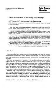
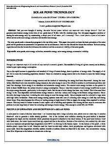
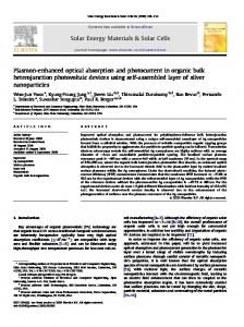
Two identical prototype solar ponds, each of 2.5 x 2 m’ surface area and 1 m depth, have been constructed and tested. The pond is made of 3 mm galvanized mild steel sheets which are insulated with 10 cm rockwool sheets. Two plexi-glass windows, each of 6 mm thickness, 50 cm width and 1 m long, were constructed to permit monitoring the inside of the pond. A schematic diagram of the solar pond is shown in Fig. 1. Floating plastic rings were used to suppress wind effects on the solar ponds. A rather new type of flat-plate collector, called the inverted trickle [7], is used for augmentation of the heat into the pond. The reason why this type of collector is selected is its high efficiency combined with less cost compared to the conventional fin-tube configuration. An illustration of the inverted trickle collector is shown in Fig. 2. This collector consists of an absorber plate, a wire screen attached to its back, and a bottom plate. The absorber plate is galvanized steel, an area of 1.7 x 0.74 rn? and a thickness of 1 mm. The wire screen is of the same area as the absorber plate. It is made with six holes per inch with wires of 0.65 mm in diameter and was attached to the galvanized steel plate by spot welding at 5 cm distance between spots. The bottom plate is galvanized steel of 1.7 x 0.74 m” and 1 mm thickness. This plate is used mainly for protecting the insulation from any water dripping that may occur during the operation of the collector. The collector is installed at a slope angle of 30”. The working fluid (water) enters the collector from the top where it is distributed on the back of the absorber plate via an inlet header. As the fluid trickles down this combined plate-wire screen surface, it heats up and is collected at the bottom. By this arrangement, solar energy absorbed at the top of the absorber plate is directly conducted to the fluid with negligible resistance (this is mainly the reason behind the high efficiency of this type of collector). A heat exchanger was designed and installed in the solar pond to allow the heat transfer augmentation of the solar energy collected by the solar collector. The heat exchanger was made of a cross linked polyethylene pipe (XLPE) with a spiral shape and was submerged in the bottom of the pond. The (XLPE) pipe was used on account of its good heat transfer characteristics and its resistance to corrosion. A schematic diagram showing the assembly of the solar pond with the inverted trickle collector is shown in Fig. 3. The ponds were filled using the redistribution technique described by Zangrando [8]. By considering the lower convective zone is of depth L, concentration C and surface area A, and the nonconvective zone is of depth H, the pond is originally filled to a depth (L + H/2) with a brine at the maximum concentration of 20%. Once this has been done, fresh water was added to the Note: All dimensions in mm
Column to hold thermocouples & pipes
Fig. I. Schematic diagram of the solar pond.
JUBRAN et al.: SOLAR ENERGY AUGMENTATION
OF A CARNALITE
SOLAR POND
241
Outlet header Fig. 2. Schematic
cross-section
in the inverted
trickle collector.
pond through the diffuser at the top of the lower convective zone. The salt which was used in the ponds is the Carnalite salt (KCl.MgC12.6H20) harvested from the Dead Sea by the Arab Potash Company. This salt is available in commercial quantities from the Dead Sea, and the cost of using such a salt in Jordan is minimal.
Trickle collector \
4
Expansion tank By-pass ._/
I
I --
Pump Fig. 3. Schematic ECM
3813-X
-
-.\
Flow meter Solar pond
of the solar system.
248
JUBRAN ef
a/.:
SOLAR ENERGY AUGMENTATION
OF A CARNALITE
SOLAR POND
Tmax. . . . . . . . . . . ..Tamb.
d
s
L:
ki
s
a
Month Fig. 4. Monthly maximum temperature history in the storage zone without the augmentation system.
The temperature profile has been monitored four to five times a day and three times a week by installing a set of 10 Copper-Constantan (type T) thermocouples which were fixed at equally spaced distances of 10 cm in depth, starting from 5 cm above the bottom of the pond. These thermocouples were fixed on a 1 m long rod which is 50 cm away from the North facing of the pond wall. The temperature readings were taken directly by connecting these thermocouples to a 10 channel microprocessor. The salinity profile of the pond was measured by withdrawing samples from fixed ports located at equally spaced distances of 10 cm in depth, starting from 5 cm above the bottom of the pond.
“A +B
Temperature(“C) Fig. 5. Temperature profile inside the pond, at 9:00 on 2/10/94, Tarnb= 251°C.
JUBRAN et al.: SOLAR ENERGY AUGMENTATION
OF A CARNALITE
SOLAR POND
249
loo r
Temperature (“C) Fig. 6. Temperature profile inside the pond, at II:00 on 2/10/94, Tdmb= 27.3 C
These ports are fixed on a 1 m long rod. The samples were withdrawn using manual pumps. The samples were then left to be cooled to 20°C and then weighed using 50 ml specific gravity bottles. The salinity profile was measured at least once a week. The meteorological data, namely, the solar radiation, ambient temperature, relative humidity and wind speed were obtained from the Jordanian Meteorological Department for the years 1993 and 1994. 3.
RESULTS AND DISCUSSION
Throughout the measurements made to establish the data presented in this paper, care was taken to note possible sources of error and an error analysis based on the method of Kline and McClintock [9] was carried out. The error analysis indicated that the errors in the temperature and the specific gravity are less than 1%. Some of the measurements were repeated a few times, and it was found that the repeatability of the specific gravity measurement is +2%. Two identical solar ponds were constructed so that one of them will be used as a reference pond, while the other is used to investigate the augmentation of the solar pond using the inverted trickle solar collector. Figure 4 shows the maximum temperatures history of the storage zone without the 100
90
XA +B
Temperature (“C) Fig. 7. Temperature profile inside the pond. at 12:OOon 2/10/94. Krnk= 27.8 C.
250
JLJBRAN et al.: SOLAR ENERGY AUGMENTATION
OF A CARNALITE
SOLAR POND
W90-
XA
+B
Temperature (“C) Fig. 8. Temperature profile inside the pond, at 14:00 on 2/10/94, Tvmb= 282°C.
augmentation system at different times of the day for 9 months. These figures indicate that a maximum temperature of 42°C is obtained in the storage zone, and that occurs in July. Furthermore, the energy stored in the pond is increased with the life of the pond. In order to study the effects of the augmentation system on the stability and performance of solar ponds, one of the ponds (labeled A) was used to accommodate the augmentation system (the solar collector and the heat exchanger), while the other pond (labeled B) with no augmentation system was used as the reference one. Figures 5-8 show the effects of adding the augmentation system after 5 days of operation during October on the temperature profiles. The reference pond B and the pond A with the augmentation system tend to exhibit the same temperature profiles in the morning, Fig. 5. On the other hand, at noon, 2:00 and 3:00 p.m., there is strong evidence that the effect of the augmentation system on pond A is to increase the storage zone temperature by 8°C
XA +B
Temperature(“C) Temperatureprofile inside the pond, at 15:OOon 2/10/94, TrFnb= 28.3’C
JUBRAN er al.: SOLAR ENERGY AUGMENTATION
OF A CARNALITE
SOLAR POND
251
x Before operation + After operation
Specific gravity Fig. 10. Effect of collector on salinity profile, on 22110194.
when compared with pond B, but at the same time, the stability of the pond is almost unaffected as can be seen from the temperature profile in the gradient zone, Figs 6-8. For pond B, these figures indicate clearly the three regions of the solar pond, where the lower convective zone (LCZ) thickness is around 10 cm and the nonconvective zone (NCZ) region thickness is limited to 38 cm and a temperature gradient of 35”C/m. On the contrary, pond A has a temperature gradient in the LCZ, and the temperature is not any more constant in this lower zone. It is interesting to note that, in the morning, although there is a temperature difference between the storage zones of pond A and B, the gradient which has appeared in the storage zone during the previous day has already disappeared, indicating that the solar pond has adjusted itself during the night, giving a constant temperature profile in this region for the morning period, Fig. 9. The salinity profile for pond A when the augmentation system is either operational or not is shown in Fig. 10. It is clear from this figure that the salinity profile of the pond is not affected by the presence of the solar energy augmentation system. The scatter of the points of the salinity profiles of the pond with and without the augmentation system is about the same, hence the stability of the pond is not affected. The salinity profiles with the augmentation system present were taken weekly, and no effect of the augmentation system was observed. 4. CONCLUSION
An experimental investigation was conducted to study the effects of a solar energy augmentation system on the characteristics of Carnalite solar ponds. It was found that adding a supplementary collector with a heat exchanger will not disturb the concentration gradient of the pond but will enhance the collection of solar radiation and store it in the lower convective zone. Furthermore, it was found that the inverted trickle collector works well with the solar pond. The use of a cross linked polyethylene pipe as a heat exchanger provided good corrosion resistance and good heat transfer characteristics. authors would like to thank the Jordanian Higher Research Council and the Jordanian Industrial Bank for sponsoring this work. The authors would also like to acknowledge the valuable assistance of Mr. A. Shaheen. who helped in conducting the tests, and the University of Jordan for using its facilities in the research. Acknou~ledgemenw-The
252
JUBRAN et al.: SOLAR ENERGY AUGMENTATION
OF A CARNALITE
SOLAR POND
REFERENCES I. J. Hull. C. Nielsen and P. Golding, Sulinit~ Gradient Solar Ponds. CRC Press, Boca Raton, FL (1987). 2. R. Beniwal, R. Singh, N. Saxena and R. Bhandari, Heat Recosery Systems, 6, 105 (1986). 3. D. Munoz, F. Zangrando, R. Viskanta and F. Incropera, Transactions of ASME, J. of Solar Engineering, 110, (1988). 4. F. Banat, A study of Carnalite salt-gradient solar ponds. MSc. thesis, University of Jordan (1990). 5. Y. S. Cha, W. T. Sha and S. L. Sod, Transactions-of ASME, J. of Solar Engineering, 105 (1983). 6. N. Isshiki. Y. Kurosaki and N. Hatoh. Solar Enewv 35. 97 (1990). 7. A. Badran and Y. Najjar, hr. J. Solar Energy 14,?3 (lb93).’ 8. F. Zangrando, Solar Energy 25 (1980). 9. S. Kline and F. McClintock, Mechanical Engineering 75 (1953).