This paper describes a method of solid modeling using boundary integral equations ... equations(PDE) are used to generate many kinds of free-form surfaces3 â¢.
SOLID MODELING USING BOUNDARY INTEGRAL EQUATIONS Yoshihiro OCHIAI
Kinki University, 3-4-1 Kowakae, Higashi-Osaka City, 577-8502, Japan
Abstract This paper describes a method of solid modeling using boundary integral equations and three-dimensional polyharmonic functions. This method requires arbitrary points and lines on a free-form surface of a solid model. The free-form surfaces of the solid model are searched, after solving the discretized integral equation. In this paper, the integrated polyharmonic functions are derived. These functions effectively smooth the obtained surface even if functions of low order are used. The complicated and smooth free-form surface of the solid model can be expressed by only one surface patch. In order to investigate the efficiency of this method, several examples are presented. Key Words: Modeling, Drawing, Surface Generation, CAD, Boundary Element Method, Design
1. INTRODUCTION In defining a free-form surface in interactive CAD, surfaces are generated using a Bezier spline and a B-spline1•2 • In the method using the B-spline, points must be assigned in a gridiron layout. Partial differential equations(PDE) are used to generate many kinds of free-form surfaces3 • However, PDE cannot use scattered data. Optimization techniques are used to generate a smooth free-form surface, which is a B-spline surface4 • A method using soft objects has been proposed5•6,but it is difficult to define an exact position of points on a surface. On the other hand, the radius spline is proposed7•8 • The author has proposed a method using boundary integral equations and poly harmonic functions in order to generate a 2.5-dimensional free-form surface9•10•11 • In the above-mentioned two methods, points can be assigned arbitrarily instead of using a gridiron layout, making it easy to generate a free-form surface. In the method using the integral equations, it is quite simple to generate a 2.5-dimensional free-form surface. This paper describes a method of solid modeling using boundary integral equations and the three-dimensional poly harmonic functions. In F. Kimura (ed.), Geometric Modelling © Springer Science+Business Media New York 2001
this paper, a fictitious big box, in which a solid is defined, is considered. In order to obtain a smooth surface using lower-order polyharmonic functions, a new function, which expresses a state of a uniformly distributed poly harmonic function in a spherical region, is introduced. A new integral equations are proposed using these new functions.
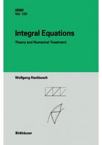
2. THEORY 2.1 Fundamental equation In this theory, the Poisson equation, which is used for heat conduction analysis with heat generation, is applied to define a solid geometry. In the one-dimensional case, linear interpolation, as shown in Fig.l, can be described by
V(I/T1 =- TP z
(1)
where V< 1>2 is d2/dx 2• The term TP2 corresponds to an unknown point heat source. Smoother interpolation is obtained by
V(I/T1 = -T 5 z
(2)
V(1l2T2=-TP3.
(3)
From Eqs.(2) and (3), the following equation can be obtained.
v (l)"T I =T/
(4)
This equation is the same type of equation as that for the deformation (T 1) of a thin beam with an unknown point load (TP3). The unknown point load
~
(a) Linear interpolation (b) Beam for interpolation Figure.] One-dimensional interpolation
t Figure.2
Fictitious thin plate for interpolation
210
(TP3) can be obtained inversely using a value ofT 1 at several points, as shown in Fig.2. The term T 5 2 corresponds to the moment of the beam, and the term T 5 2 at both ends of the beam is assumed to be 0. The obtained curve corresponds to the natural spline. In the two-dimensional case, interpolation can be describe by (Ochiai and Yasutomi 13, 2000)
V1' ~=-rz V
(5) (6)
(2)1's2=-TPJ
where V 2=ii/iJx2+i//iJy2• From Eqs.(5) and (6), the following equation can be obtained. (7) This equation is the same type of equation as that for the deformation (T 1) of a thin plate with an unknown point load (TP3), as shown in Fig.2. The unknown point load (TP3) can be obtained inversely using a value ofT 1 at several points. The smoother free-form surface can be obtained using a uniformly distributed load (TP3A) on area A instead of a point load (TP3). (Ochiai and Yasutomi, 2000) A 2.5-dimensional free-form surface can be obtained using the above-mentioned method. Figure 3(a) shows a line of given boundary geometry and arbitrary internal points. Figure 3(b) shows an obtained shape. In the three-dimensional case, the Poisson equation, which is used for heat conduction analysis with heat generation, is applied to define a solid geometry. Solid geometry is assumed as the part of which values are less than zero. It is assumed that the value T 1 at an arbitrary point P satisfies the Poisson equation
(8) The term T 2 is a function of ( x, y, z) including infinite values . It corresponds to the sum of approximated
(a) Given data
(b) Obtained shape
Figure .3 2.5-dimensional shape
211
Figure.4
Notations for new function
curvatures iiTdax 2 , a2T 1/ ay 2 and iT 1/ or. The surface of the solid is an iso-surface with value 0. The three-dimensional i-th polyharmonic function T.;(P, Q) and its normal derivative aT·;an can be given by9 2i-3
T··(P Q)--r_ _
(9)
or an
(10)
- 4n(2i- 2)!
'
'
aT·;
(2i- 3)r 2;- 3
an
4n:(2i- 2)!
--=
Denoting by r the distance between two points ( P, Q) , where P and Q are the source point and the observing point, respectively. In order to obtain a smooth surface using lower order polyharmonic functions, a new function T.;A, which expresses the state of a uniformly distributed polyharmonic function in a spherical region with radius A, as shown in Fig.4, is introduced.
T
·
iA
=
Jor- Jor" Jor" T ·;ad8dda
(11)
The newly defined function T.;A and its normal derivative are shown explicitly. These functions are given by using r similarly in Eqs.(9) and (10), though the functions obtained from Eq.(11) are the functions of R. •
A3
T1A=-
3r 3A 2 - r 2 T.tA = 6 T•zA =
T•zA =-
l
A' A' [ r 2 +5 fu
r 4 -15A4 -10r 2A 2 120
r>A
(12)
r~A
(13)
r>A
(14)
r~A
(15)
The term T 2 in Eq.(8) can be divided into several terms as follows 9· 11 : 212
r
T2=Tv2+T5 2+TL2+Tpz+T 0 z+ 2A+T0 2A+TL2A +Tp2A
(16)
where TP2 is a Dirac-type function, which has a value only at a point and similarly TL2 has the value only on a line and T52 on a surface. Moreover, point TP2A and line TL2A are related to the new function T 2A. On the other hand T 0 2 and T 0 lA are concerned with aT jan and aT;Jan, which correspond to the double layer along a form of a surface. Equation (8) can be written as follows: V2Tv1= -(Tv2+T 52+TL2+TP2+T 0 2+T5 2A+T0 2A+TL2A+TPZA)
(17)
Generally, the next equation
is assumed. Moreover, in the case of i=l, we assume Tvl+ 1=0 and we obtain vurv,=-(Tvl+l+T 51+1+TLI+l+Tpl+l+T0 i+l+T5t+IA+T 0 1+1A +TLI+IA+Tpi+IA) (19)
r,
Considering the fictitious box as a boundary the value T 1 at an arbitrary point is given by Eqs.(8) and (16)"-'(19) and Green's second identity as follows 9•11 : cTv,(P) =-
* f:f
(-1);/r {T.;(P,Q) aTv;(Q)- aT*;(P,Q) Tv;(Q)}dr(Q)
an
an
- ~frs (-lYT.;Tsi+ldrs- ~ (-l)iT.;(P,q)Tri+l(q) I
I
where rs, rL and ro show the forms of T5;, TL; and T 0 ;. On the smooth boundary r c=0.5, for the inside of the boundary c=l.O and for the outside of the boundary c=O. 2. 2 Unit normal vector Unit normal vector on a surface is important in CAD. Differentiating Eq.(20) with Xt, the next equation is obtained.
213
where (22) (23) Functions iJT;A/iJxk are given as follows:
aT·tA A 3 ar ~=-3r 2 axk aT·tA
r
r>A
ar
--=---
3 axk aT*2A A 3 (r 2 -5A 2) ar --=axk 30r 2 axk
(25)
axk
aT*2A
--=-
r 3 -5rA 2 iJr
(24)
r>A
(26)
r~A
(27)
The N; component of a unit normal vector is given by
aTvt(P)
(28)
214
3. NUMERICAL PROCEDURE OF INTEGRAL EQUATION As it is difficult to treat the integral equation (20) analytically, they are discretized and treated numerically. Various examples using integral equations can be shown. In this paper, the term TP3A and 1=2 are used. We obtain the following equations from Eqs.(17) and (19). V2T~=-Tvz
(29)
V2T\=-TP3A
(30)
Denoting the number of points as M, we obtain the following integral equations from Eqs.(29) and (30)
The boundary r is discretized by the constant elements. Replacing Tv; and aTv; /on by vectors T; and V;, respectively, and expressing Eq.(31) as matrices, we obtain 12 (33) where G 11 H 11 G 2 , H 2 and GP2 are the matrices with the following elements for a given boundary point 'e':
G1ej
=
(34)
fr.T.I(P,Q)drj l
H . =!b .. + r aT.i(P,O) ctr. lej 2 IJ Jrj an J
(35)
G 2ej
(36)
=
j;T.z(P,Q)drj l
H .= 2ej
p
G zek
r aT.z(P,Q) ctr. an
Jr; =
•
J p
T zAk(P,q ) .
(37)
(38)
rj
is the discretized boundary. Notations p and q are used for internal points instead of P and Q. When the case of 1=2 is considered, the following equation is obtained from Eq.(32): (39) 215
where Gr 1 is the matrix with elements p
•
p
G lek = T lA (P, Q ) .
(40)
Moreover, using the internal points with value T(pPA) which is related to TP3A, we obtain T(pP)=-H 3T 1+G 3V 1+H 4T 2-G 4V2-GP3TP3
(41)
,
where G 3 , H 3 , G 4 , H4 and Gr3 are the matrices with elements (42) (43) (44) (45)
GP3ek = T*zA(PP ,qp) ·
(46)
Assuming T 2=0 and using Eqs.(33), (39) and (41), we obtain
(47)
Using the above equation, Vp V 2 and Tr3 can be obtained. The value at an arbitrary inner point can be obtained by Eq.(31). Using the above method, a solid can be defined. Voxels can be used to show a solid object. Scanning inside the region, a small voxel is created if the value at the point is smaller than zero. This method can be easily applied to stereolithography. The other method is shown in Fig.5. First, coarse triangular patches are given, and normal vectors are given using Eq.(28) at the middle point of each side of the triangle. Searching the point of value zero, four new patches are made. Repeating this process, smooth surfaces can be obtained. Similarly, marchine cubes method can be used.
- t; ' ',p ' ·· ... , I
-----Figure.5
,.. -
Generation of new surfaces
216
-
...
4. NUMERICAL EXAMPLES In this method, a fictitious big box, in which the solid is defined, is considered. The value of the box surface is assumed to be + 1. The surface of the box is divided into elements, as shown in Fig. 6(a). In the simplest example, the free-form surface, defined by nine points on the surface and one internal point (Fig. 6(b)), is obtained using several functions and parameters. As shown in Figs.7(a)--(e), the surface becomes smooth by increasing the number i of function T*;· If the same number i is used, the surface defined by T*;A is smoother than that defined by T.;. The surface becomes smooth with increasing parameter A. Using the constant elements and M internal points and dividing the boundary of the fictitious big box into N , the simultaneous linear algebraic equations with (IN+M) unknowns must be solved. If T. 2A is used with a larger value of A, the shape in Fig. 7(b) is similar to the shape in Fig. 7(c) and the calculation time is much shorter than that using T• 3 • To construct a shape with two projections, several smooth solids are created with the surface points as shown in Fig.8. The point with value + 1 is given in the middle of the two projections in order to avoid connecting them. In this method, a solid is defined only by points, and Fig. 9 shows the voxel shape obtained from these points. It is a possibile to apply this method to stereolithography. If voxeles are used to construct the shape, the shape is unclear. The triangular patches are used to avoid this. First, the rough triangular patches are given, the fine triangular patches are calculated by using the method shown in Fig.S. Figures 10(a) and (b) show the shapes obtained using T• r and T* 2A> respectively. As a useful application of this method, a human face is obtained from surface points. Figure 11 (a) shows the given surface points in the front view. Though points on the top of the head and the side of the face are not given as shown in Fig.ll(a), a smooth surface is created through the calculation. Giving the patche by an operator requires far too much time, so 20 rough triangular patches are given using only 12 points as shown in Fig. 11 (b) . After repeating the calculation as shown in Fig.S four times, a human face can be obtained from the given points as shown in Fig.10. Function T* ZA with A=0.05 is used. It became clear that smooth solid modeling can be carried out using a limited amount of data. Ray casting14 for modeling solids is effective for the present method. Surface points on the Venus de Milo are shown in Fig.13(a), and Fig.13(b) shows the side and front views of the Venus de Milo obtained by ray casting and Eq.(47). A solid can also be defined by lines instead of points. Figure 14(a) shows the given lines, and the obtained solid is shown in Fig.14(b). 217
/ L/
//
v
/vyvv vVV/ / v /
Vv v /v/Vv vvv/v v
-I
0
+1
(a) Boundary Figure. 6
(b) Given points Boundary and given points
(a) T'w A=l.5
(c) T'w A=O.l
Figure. 7 Example of obtained shapes
(