May 20, 2015 - Austenitic with small quantities of martensite for 35 % dilution (uncommon) ...... [35] M.F. Gittos and T.G. Gooch. The interface below stainless ...
Solidification and phase transformations in a dissimilar steel weld 18MND5/309L/308L : evolution of microstructure and mechanical properties Fanny Mas
To cite this version: Fanny Mas. Solidification and phase transformations in a dissimilar steel weld 18MND5/309L/308L : evolution of microstructure and mechanical properties. Materials. Universit´e de Grenoble, 2014. English. .
HAL Id: tel-01153912 https://tel.archives-ouvertes.fr/tel-01153912 Submitted on 20 May 2015
HAL is a multi-disciplinary open access archive for the deposit and dissemination of scientific research documents, whether they are published or not. The documents may come from teaching and research institutions in France or abroad, or from public or private research centers.
L’archive ouverte pluridisciplinaire HAL, est destin´ee au d´epˆot et `a la diffusion de documents scientifiques de niveau recherche, publi´es ou non, ´emanant des ´etablissements d’enseignement et de recherche fran¸cais ou ´etrangers, des laboratoires publics ou priv´es.
THÈSE Pour obtenir le grade de
DOCTEUR DE L’UNIVERSITÉ DE GRENOBLE Spécialité : Matériaux, Mécanique, Génie civil, Electrochimie Arrêté ministériel : 7 août 2006
Présentée par
Fanny MAS Thèse dirigée par Yves BRECHET et codirigée par Catherine TASSIN préparée au sein du Laboratoire SIMaP dans l'École Doctorale I-MEP2
Solidification and phase transformations in a dissimilar steel weld 18MND5/309L/308L: Evolution of microstructure and mechanical properties Thèse soutenue publiquement le 19 décembre 2014, devant le jury composé de :
M. François MUDRY Président de l’IRT M2P, Président
M. Jacques LACAZE Directeur de recherche CNRS, CIRIMAT, Rapporteur
M. Mohamed GOUNE Professeur, ICMCB, Rapporteur
M. Yves BRECHET Professeur, Grenoble INP, Directeur de thèse
Mme Catherine TASSIN Maître de Conférence, Grenoble INP, Co-directeur de thèse
Mme Aude SIMAR Professeur, Université Catholique de Louvain, Examinateur
M. Ernst KOZESCHNIK Professeur, Vienna University of Technology, Examinateur
M. François ROCH Ingénieur chercheur, AREVA NP, Invité
M. Patrick TODESCHINI Ingénieur chercheur, EDF R&D, Invité
Remerciements Ça y est, la version dé�nitive du manuscrit est bouclée mais il me reste une tâche de taille : trouver les mots justes pour vous remercier, vous qui avez fait de ces trois années de thèse une aventure exceptionnelle, métallurgiquement très enrichissante, et humainement très forte. Je tiens tout d'abord à remercier l'ensemble des membres de mon jury qui ont accepté de prendre part à ma soutenance, chacun apportant sa contribution à cette matinée de discussion scienti�que. Merci à François Mudry qui a présidé ce jury avec beaucoup d'humour rendant l'atmosphère générale agréable et détendue. Merci à Jacques Lacaze et Mohamed Gouné pour le soin apporté à la relecture du manuscrit, vos remarques et suggestions m'ont permis de prolonger la ré�exion et de soulever de nouvelles questions. J'adresse un merci tout particulier à Yves Bréchet et Catherine Tassin qui m'ont fait con�ance tout au long de cette thèse et qui ont su me transmettre leur passion pour la métallurgie physique. Yves, j'ai beaucoup apprécié le temps que tu as su trouver dans ton emploi du temps très chargé pour examiner avec moi les nombreuses problématiques scienti�ques liées aux soudures bimétalliques. La grande diversité de ton expertise et la pertinence de tes suggestions ont guidé mes pas de jeune métallurgiste. Catherine, je te remercie pour m'avoir accompagné au jour le jour et pour avoir toujours répondu positivement à mes nombreuses sollicitations. Ton soutien et ton optimisme à toute épreuve m'ont aidée à ne pas baisser les bras dans les moments di�ciles. Cette thèse a été l'occasion de réunir les trois acteurs principaux du nucléaire Français autour d'un sujet commun : le vieillissement des LBM inox. Merci donc à EDF et Areva qui ont co-�nancé ce travail, mais également au CEA qui m'a permis de subtiliser un peu de son temps à son HautCommissaire. Je tiens à remercier tout particulièrement François ROCH qui a été à l'origine de ce sujet tout aussi complexe que passionnant et qui m'a fait con�ance pour le mener à bien. Merci également à Miguel Yescas, Patrick Todeschini, Cécile Jardin et Jean-Paul Massoud qui ont accepté de se joindre à cette aventure. J'exprime également un grand merci à Gilles Perrin pour l'intérêt qu'il a porté à mon travail lors de nos nombreuses discussions mécaniques et métallurgiques à Grenoble comme à Paris. Ces travaux de thèse ont donné lieu à de nombreuses collaborations, deux d'entre elles me sont particuliérement chères. La première m'a conduit chez nos voisins Wallons : tout d'abord merci à Aude Simar pour m'avoir initié à la rupture ductile et à sa modélisation. Ta gentillesse à mon égard et ton écoute ont été sources de motivation. J'ai énormément appris à ton contact et mon seul regret est de ne pas avoir commencé à travailler ensemble dès le début de ma thèse. J'espère que
1
nous aurons l'occasion d'interagir à nouveau, peut-être autour du soudage et/ou de la rupture des alliages d'alumminium ! La seconde collaboration a eu lieu dans la capitale autrichienne : merci à Ernst Kozeshnik et Yao Shan pour les nombreux échanges autour de la modélisation de la di�usion et de la précipitation. Merci pour votre accueil chaleureux lors de mes venues à Vienne. Même si la distance n'a pas facilité notre collaboration, je suis extrêmement reconnaissante pour le temps que vous avez consacré à développer les aspects numériques de ce problème complexe qu'est le couplage di�usion-précipitation. Nombreuses sont les personnes qui ont consacré un peu (voire beaucoup) de leur temps à m'aider pour les caractérisations microstructurales et mécaniques de cette thèse. Je tiens à les remercier fortement :
•
Nathalie Valle pour les mesures SIMS (Centre Public Gabriel Lippmann, Luxembourg)
•
Emmanuel Rigal pour la fabrication de couples de di�usion par CIC (CEA, Grenoble)
•
Cyril Cayron pour son aide à l'utilisation d'ARPGE (EPFL, Lausanne)
•
Patrick Barges (Arcelor Mittal, Maizières) et Sophie Cazottes (INSA Lyon) pour les répliques extractives
•
Laurent Artaud pour le montage de décarburation (SIMaP)
•
Marion Descoins et Dominique Mangelink à la sonde atomique (IM2NP, Marseille)
•
Marc Verdier à la naoindentation (SIMaP)
•
Muriel Veron et Gilles Renou au MET (SIMaP)
•
Eric Leroy au MET-FEG (ICMPE CNRS)
•
Pierre Chemelle, Marie-Line Astier et Marc Mantel (Ugitech) pour les réponses toujours positives aux besoins de dépannage d'urgence (EBSD, répliques, analyse chimique)
•
Guilhem Martin (SIMaP) pour la corrélation d'images mais avant tout pour son dynamisme et sa motivation sans faille qui m'ont énormément stimulé pour les dernières manips de la thèse.
Merci également à l'ensemble du personnel du CMTC pour les nombreux dépannages sur les outils de caractérisation, en particulier à Florence pour les nombreuses heures (jours) passées pour moi sur la microsonde et à Frédéric pour les nombreuses heures (jours) devant le FIB. J'ai aussi pu béné�cier de l'aide du pôle technique du laboratoire SIMaP qui a toujours répondu positivement à mes demandes les plus farfelues. Et surtout un grand
MERCI à Alain pour les multiples découpes
toujours réalisées en un temps record et dans la bonne humeur. Lors d'une expérience di�cile et ambitieuse à l'ESRF, j'ai béné�cié du soutien d'une équipe de choc : merci à Marc, Stéphane, Guillaume, Mahmoud, Catherine et Cécile pour le réglage des PID jusque tard dans la nuit, pour les creusets cassés et le carbone évaporé. Mes remerciements vont également à Muriel pour les
2
escapades en banlieue parisienne et les heures passées dans le noir à Thiais. Mais ce sont surtout tes encouragements tout au long de ces trois ans, ainsi que tes nombreux conseils lors de la préparation de la soutenance qui m'ont aidée à avancer. Au cours de ces trois ans, j'ai eu l'opportunité d'encadrer plusieurs stagiaires : merci à Aurélien, Jordi, Quentin et Patrice d'avoir accepté de parfois �faire la petite main�. Ils ont beaucoup contribué aux résultats de cette thèse et m'ont aussi beaucoup appris sur le plan humain. Je souhaite ègalement saluer l'ensemble des membres du groupe PM, et en particulier mes amis thésards avec lesquels j'ai notamment partagé la bonne ambiance du midi, les parties de tarot endiablées et les footings pour décompresser. J'adresse un merci tout particulier à Laurent pour son aide précieuse au cours de ces trois années à travers nos nombreuses discussions métallurgiques (et moins métallurgiques) de �n de journée (ou de début de soirée). Merci également à Audrey et Nicolas qui ont fait du bureau 222 l'endroit le plus chouette du labo. Au programme : thé, gâteaux, bonbons accompagnés de discussions politiques (avec Nicolas) ou culinaires (avec Audrey) et parfois même métallurgiques. Bonne chance à vous deux pour la suite ! Pour �nir mes remerciements vont aussi à tous ceux qui m'ont permis de me distraire, de m'évader de cette thèse trop souvent omniprésente. Merci à tous les copains (Pascal, Sophie, Mériem, Camille, Pauline, Quentin, Nico, Christine, Kilian, Frach) pour les sorties en montagne et les bonnes bou�es au retour. Merci à Papa et Maman pour leur soutien dans les moments di�ciles, pour l'accueil à Marseille pendant la rédaction, ainsi que pour pour votre aide indispensable à la réussite du bu�et. Merci à Camille et Martin pour les escapades en famille. Merci à Grand-Mère pour ton hospitalité à Lyon et les bons petits plats. Merci en�n à Yannick pour tous les bons moments passés à tes côtés.
3
4
Résumé étendu Chapitre 1 - Introduction : motivations industrielles et scienti�ques (p.7-14) Contexte Les soudures en aciers dissimilaires connues sous le nom de "liaisons bimétalliques inox" sont nombreuses au sein des réacteurs nucléaires français actuels. Elles permettent la connexion entre les gros composants de la centrale (cuve, pressuriseur, générateur de vapeur) en acier faiblement allié (16MND5, 18MND5, 20MND5) et les tuyauteries du circuit primaire en acier inoxydable (316L). Comme le montre la Figure 1, plusieurs couches de beurrage en acier inoxydable 309L et 308L sont d'abord déposées sur l'embout en acier faiblement allié, qui est ensuite soudé à une bague en acier 316L à l'aide d'un métal d'apport en acier inoxydable austénitique (308L). Le soudage homogène entre la bague intermédiaire et la tuyauterie peut ensuite être réalisé sur site.
Figure 1: a- Représentation schématique d'une LBM entre un composant en acier faiblement allié et une tuyauterie en acier inox ; b- Macrographie mettant en évidence les interfaces entre alliages dissimilaires.
Le revêtement interne des composants en acier faiblement allié est un autre cas de soudage dissimilaire. Il a pour rôle d'assurer la protection contre la corrosion face à l'eau du circuit primaire. Dans le contexte de l'extension de durée de vie des centrales nucléaires françaises, se pose
5
la question du vieillissement thermique de ces liaisons bimétalliques : comment les di�érentes microstructures présentes autour de l'interface évoluent-elles lorsqu'elles sont soumises à une tempé-
◦
rature autour de 300 C pendant plusieurs dizaines d'années ? Les propriétés mécaniques de l'assemblage se dégradent-elles ? C'est pour répondre à ces problématiques qu'un projet d'ingénierie commun EDF-AREVA comprenant de nombreux essais mécaniques et caractérisations après vieillissement a été lancé �n 2011. Le travail de thèse qui va être décrit dans la suite a pour vocation de fournir un support scienti�que à ce programme de R&D.
Matériaux et soudage Pour des raisons pratiques, les soudures dissimilaires de cette étude ont été réalisées par soudage à l'arc sous �ux de deux couches d'aciers inoxydables (309L et 308L sous forme de feuillards) sur une tôle en acier faiblement allié 18MND5. Elles sont donc représentatives du revêtement interne des gros composants de la centrale. La composition chimique du métal de base et des métaux d'apport est indiquée dans le Tableau 1 et les paramètres de soudage dans le Tableau 2. La tôle ainsi revêtue a été découpée en quatre blocs d'égales dimensions, l'un d'entre eux étant conservé à l'état brut de soudage. Le traitement thermique de détensionnement, dont le but est de relaxer les contraintes internes accumulées lors du soudage, a été appliqué aux trois autres. Il comprend les étapes suivantes :
•
Chargement dans un four froid
•
Montée en température : 30 C/h
•
Maintien en température à 610 C pendant 8 heures
•
Rampe de refroidissement : 25 C/h jusqu'à 300 C
•
Refroidissement à l'air libre
◦
◦
◦
◦
Seul l'un des échantillons précédent a été conservé à l'état détensionné, des traitements de vieil-
◦
lissement accéléré à 400 C ont été appliqués aux deux autres : l'un pendant 5000 heures et l'autre pendant 10000 heures.
Tableau 1: Composition chimique des alliages en présence.
18MND5 (pds%) 309L (pds%) 308L (pds%) 18MND5 (pds%) 309L (pds%) 308L (pds%)
C
Si
Mn
Ni
Cr
Mo
Cu
0.199
0.219
1.623
0.635
0.231
0.479
0.114
0.021
0.359
1.698
12.57
23.66
0.068
0.023
0.011
0.152
1.671
10.43
20.04
0.014
0.025
S
P
Al
Co
Ti
N
Fe
0.0019
0.0048
0.028
0.011
1), notamment au contact du liseré martensitique. En revanche, cette zone est quasiment vierge en termes d'inclusions de taille signi�cative. En e�et, les carbures de cémentite ont été dissouts lors de la décarburation ; seuls subsistent quelques sulfures de manganèse. En ce qui concerne les couches d'acier inoxydable, elles sont larges (≈ 4 mm) et la contrainte générée par la partie carburée de l'austénite ne s'exerce qu'en son voisinage. En ce qui concerne les inclusions, elles sont nombreuses. On y trouve :
•
les oxides de �n de solidi�cation qui sont des particules sphériques dont le diamètre varie entre 250 nm et 5
•
µm.
les interfaces
δ -γ
qui, dans l'état détensionné, sont décorées par un �lm quasi-continu de
carbures. Lors des essais de traction sur la soudure globale, la rupture a systématiquement lieu dans la deuxième couche de revêtement en 308L, dans l'état brut comme dans l'état détensionné. Néanmoins, comme le montre la Figure 17, on constate une diminution de la déformation à rupture, estimée par l'intermédiaire de la réduction de section, dans le cas de l'échantillon détensionné : 1.11 contre 1.50
±
±
0.13
0.036 dans l'état brut. Cette chute de ductilité est associée à l'existence de vides
allongés sur le faciès de rupture, ceux ci n'étant pas présents dans l'état brut. Ces cavités sont attribuées à la germination de vides aux interfaces à l'état détensionné par la présence des carbures la ferrite
δ -γ
M23 C6
δ.
23
(voir Figure 18-c), certainement fragilisées formés par la décomposition eutectoïde de
Figure 17: Surfaces de rupture dans l'acier 308L d'éprouvettes de traction à l'état a- brut de soudage ; bdétensionné.
Figure 18: Micrographies MEB d'une coupe longitudinale à mi-épaisseur dans une éprouvette de traction
à l'état détensionné rompue dans l'acier 308L : a- vue globale ; b- cavités ayant germées sur des oxides ; caux interfaces δ -γ .
A�n de provoquer la rupture dans la zone décarburée, des entailles circulaires centrées sur la région d'intérêt ont été ajoutées aux éprouvettes de traction. Les vides observés sur les surfaces de rupture sont plus larges : plusieurs dizaines de micromètres de diamètre contre seulement quelques micromètres dans le cas des aciers inoxydables. Cette observation est en accord avec la forte triaxialité et donc le fort taux de croissance attendu pour les cavités dans cette zone, ainsi qu'avec le nombre limité de sites de germination. D'autre part, une forte in�uence de la taille du liseré martensitique sur la déformation à rupture a été mise en évidence. Comme noti�é dans le Tableau 3, lorsque le liseré martensitique est plus épais, la déformation à rupture est diminuée. Cette chute de ductilité semble être liée à l'augmentation de la triaxialité dans la zone décarburée au contact d'une zone dure plus épaisse.
24
Tableau 3: Evolution de la déformation à rupture dans la zone décarburée en fonction de l'épaisseur du liseré martensitique
Epaisseur du liseré martensitique Déformation à rupture
5
µm
1.43
35
µm
120
1.13
µm
0.70
Modélisation micro-mécanique Dans le but de calculer la déformation à rupture des di�érentes éprouvettes, un modèle micromécanique de rupture ductile développé par Pardoen et al. [12, 13] a été utilisé. Suivant le critère proposé par Beremin [14], la germination est enclenchée lorsque la contrainte principale aux interfaces particules/matrice atteint une valeur critique. Une extension du modèle de Gurson [15] tenant compte de l'évolution de la forme des cavités au cours de la déformation permet de calculer la croissance des vides. Le début de la coalescence correspond à la localisation de la déformation plastique dans l'espace inter-vides suivant le critère de Thomason [16]. Dans la présente étude, la déformation à rupture est considérée comme correspondant au début de la coalescence dans la région la plus endommagée, si bien que la déformation supplémentaire qui serait nécessaire pour rompre l'échantillon est supposée faible. La spéci�cité de l'approche choisie est le fait que l'écoulement plastique et l'endommagement soient découplés. Ainsi le calcul a lieu en deux temps : d'abord une simulation élasto-plastique de l'ensemble de l'éprouvette sous Abaqus de laquelle sont extraites les évolutions de la triaxialité et de la déformation plastique équivalente au cours du temps pour chacun des éléments du maillage, puis un calcul axisymétrique d'endommagement pour chacun des éléments susceptibles d'être endommagés. Ce dernier fournit la déformation équivalente locale au début de la coalescence, qui permet ensuite de remonter à l'incrément de déplacement global pour lequel la réduction de section doit être calculée à l'aide du modèle par éléments �nis. Ce modèle a été utilisé pour simuler la rupture ductile à la fois dans la zone décarburée et dans le revêtement inoxydable. Malgré une étude paramétrique basée sur la variation de nombreuses grandeurs mécaniques, l'e�et de l'épaisseur du liseré martensitique sur la rupture dans la zone décarburée n'a pu être reproduit. Comme prévu, des niveaux de triaxialité plus élevés ont été obtenus dans le cas d'une martensite épaisse mais ils étaient associées à de faibles déformations plastiques, limitant ainsi la croissance des cavités. L'hypothèse de l'existence de sites de germination supplémentaires (points triples aux intersections des joints de grains notamment) qui ne seraient activés que par les valeurs de contraintes élevées présentes dans le cas d'une martensite épaisse a été émise. En revanche, le modèle capture bien l'e�et d'une fragilisation des interfaces
δ -γ
sur la
ductilité des couches de revêtement. En réduisant la contrainte critique de germination des cavités à ces interfaces de 3000 à 2300 MPa entre l'état brut et l'état détensionné, les déformations à rupture sont correctement prédites, à la fois pour les éprouvettes globales (perpendiculaires à l'interface) et pour les éprouvettes homogènes (parallèles à l'interface) prélevées dans les di�érentes couches de revêtement.
25
Conclusions Ce chapitre a permis de mettre en évidence les paramètres déterminants pour le développement de l'endommagement et la rupture ductile dans les zones molles de la liaison bimétallique. On trouve parmi eux le degré de con�nement de la région considérée ainsi que la quantité des sites potentiels de germination. L'e�et du traitement thermique sur la microstructure a des conséquences directes sur la ductilité des di�érentes régions. L'adoucissement du métal de base sur une étroite bande décarburée conduit à la concentration des déformations dans cette zone. La décomposition de la ferrite
δ
en carbures provoque la fragilisation des interfaces et donc la germination de cavités à des
niveaux de contraintes plus faibles.
Chapitre 7 - Conclusions et perspectives (p.181-190) Le dernier chapitre reprend les principales conclusions des chapitres précédents en mettant en exergue les faits marquants de ce travail, dont les principaux sont énumérés ci-dessous :
•
L'in�uence des mouvements de �uide dans le bain fondu sur l'irrégularité des microstructures d'interface a été mise en évidence.
•
L'origine de la zone purement austénitique a été éclaircie.
•
Un modèle thermo-cinétique couplant la di�usion à longue distance à la cinétique de précipitation a été développé. Il a permis de démontrer le rôle particulier joué par la martensite d'interface dans le transfert de carbone depuis le métal de base vers le métal soudé.
•
La décomposition des résidus ferritiques présents dans le métal soudé austénitique a été observée et son in�uence sur la ductilité du revêtement a été démontrée.
•
Des données microstructurales et mécaniques précises sur la zone décarburée ont été générées. Elles pourront ensuite être réutilisées dans le cadre de modélisations ultérieures.
•
La stabilité des microstructures autour de l'interface ainsi que du comportement mécanique
◦
local a été constatée à 400 C, en comparaison avec celles à la �n du traitement de détensionnement. Le manuscrit se termine en citant un certain nombre de perspectives qu'il serait possible de donner à un tel travail. Les principales concernent la modélisation, aussi bien microstructurale que mécanique. D'un point de vue thermodynamique, une amélioration de la description du liseré martensitique serait nécessaire a�n de permettre le fort niveau de sursaturation en carbone mesuré dans cette région. Cela passe par la prise en compte du piégeage du carbone au sein de la matrice, sur des sites favorables énergétiquement tels que les joints de lattes et les dislocations. D'un point de vue mécanique, la prise en compte des gradients de contrainte/déformation comme force motrice pour le développement de l'endommagement permettrait un déplacement de la zone de rupture au sein de la zone décarburée. En e�et, il est nécessaire que la rupture ait lieu à proximité du liseré martensitique pour qu'elle soit in�uencée par l'épaisseur de celui-ci.
26
Contents 1 Introduction: industrial and scienti�c motivations
33
1.1
Industrial context . . . . . . . . . . . . . . . . . . . . . . . . . . . . . . . . . . . . . .
33
1.2
Base materials and weld production
. . . . . . . . . . . . . . . . . . . . . . . . . . .
37
1.3
Outline of the thesis
. . . . . . . . . . . . . . . . . . . . . . . . . . . . . . . . . . . .
40
I The as-welded state
41
2 Transitions in solidi�cation mechanisms and microstructures
43
2.1
2.2
2.3
2.4
Literature review . . . . . . . . . . . . . . . . . . . . . . . . . . . . . . . . . . . . . .
43
2.1.1
A chemically graded assembly . . . . . . . . . . . . . . . . . . . . . . . . . . .
43
2.1.2
Martensitic layer at the interface
45
2.1.3
Solidi�cation modes in stainless steel welds
. . . . . . . . . . . . . . . . . . . . . . . . . . . . . . . . . . . . . . . . . . . .
46
Experimental methods . . . . . . . . . . . . . . . . . . . . . . . . . . . . . . . . . . .
48
2.2.1
Microstructural investigation
. . . . . . . . . . . . . . . . . . . . . . . . . . .
48
2.2.2
Composition measurements
. . . . . . . . . . . . . . . . . . . . . . . . . . . .
49
2.2.3
Study of the orientation relationships . . . . . . . . . . . . . . . . . . . . . . .
49
2.2.4
Thermodynamic calculations and DSC measurements . . . . . . . . . . . . . .
50
Results . . . . . . . . . . . . . . . . . . . . . . . . . . . . . . . . . . . . . . . . . . . .
50
2.3.1
. . . . . .
50
. . . . . . . . . . . . . . . . . . . . . . . .
51
Overview of the diversity of microstructures around the fusion line 2.3.1.1
The base metal 18MND5
2.3.1.2
The interfacial martensitic layer
. . . . . . . . . . . . . . . . . . . .
53
2.3.1.3
The austenitic weld metal . . . . . . . . . . . . . . . . . . . . . . . .
55
2.3.2
Compositional evolution in the boundary layer
. . . . . . . . . . . . . . . . .
55
2.3.3
Morphological evolution and change in the solidi�cation mode . . . . . . . . .
57
2.3.4
Orientation relationship between base and weld metals . . . . . . . . . . . . .
60
Discussion . . . . . . . . . . . . . . . . . . . . . . . . . . . . . . . . . . . . . . . . . .
63
2.4.1
Solute transport in the liquid boundary layer
. . . . . . . . . . . . . . . . . .
63
2.4.2
Plane front solidi�cation . . . . . . . . . . . . . . . . . . . . . . . . . . . . . .
64
2.4.3
Origin of the purely austenitic zone . . . . . . . . . . . . . . . . . . . . . . . .
65
2.4.4
Formation of ferrite in the inter-cellular space . . . . . . . . . . . . . . . . . .
68
2.4.5
Growth competition between ferrite and austenite
70
27
. . . . . . . . . . . . . . .
Contents
2.5
Summary and conclusions
. . . . . . . . . . . . . . . . . . . . . . . . . . . . . . . . .
73
II Carbon di�usion and precipitation during post-welding heat-treatment 75 3 Metallurgical characterization of coupled carbon di�usion and precipitation in dissimilar steel welds 77 3.1
Introduction . . . . . . . . . . . . . . . . . . . . . . . . . . . . . . . . . . . . . . . . .
77
3.2
Experimental procedure
. . . . . . . . . . . . . . . . . . . . . . . . . . . . . . . . . .
79
3.2.1
Carbon content measurements . . . . . . . . . . . . . . . . . . . . . . . . . . .
79
3.2.2
Nanoindentation
80
3.2.3
Precipitates identi�cation
. . . . . . . . . . . . . . . . . . . . . . . . . . . . .
80
3.2.4
Carbides quanti�cation . . . . . . . . . . . . . . . . . . . . . . . . . . . . . . .
81
3.2.5
Elements distribution
. . . . . . . . . . . . . . . . . . . . . . . . . . . . . . .
82
. . . . . . . . . . . . . . . . . . . . . . . . . . . . . . . . . . .
83
3.3
Results and discussion 3.3.1
Carbon pro�le across the fusion line
3.3.2
Nature and composition of the precipitates
3.3.3
3.3.4
3.4
. . . . . . . . . . . . . . . . . . . . . . . . . . . . . . . . . .
86
. . . . . . . . . . . . . . . . . . . . . . . . .
86
In the martensitic layer
3.3.2.2
In the fully austenitic region
3.3.2.3
In the
. . . . . . . . . . . . . . . . . . . . . .
89
weld metal . . . . . . . . . . . . . . . . . . . . . . . . .
91
Evolution of the carbides population around the interface
. . . . . . . . . . .
94
. . . . . . . . . . . . . . . . . . . . . . . . .
94
3.3.3.1
In the martensitic layer
3.3.3.2
In the fully austenitic region
. . . . . . . . . . . . . . . . . . . . . .
96
Elements distribution within matrices and precipitates . . . . . . . . . . . . .
98
3.3.4.1
In the tempered martensitic layer
98
3.3.4.2
In the fully austenitic region
Summary and conclusions
. . . . . . . . . . . . . . . . . . .
. . . . . . . . . . . . . . . . . . . . . . 102
. . . . . . . . . . . . . . . . . . . . . . . . . . . . . . . . . 104
4 Modeling coupled carbon di�usion and precipitation in dissimilar steel welds 4.1
107
State of the art . . . . . . . . . . . . . . . . . . . . . . . . . . . . . . . . . . . . . . . 107 4.1.1
4.1.2
4.1.3 4.2
83
. . . . . . . . . . . . . . . . . . .
3.3.2.1
δ−γ
. . . . . . . . . . . . . . . . . . . . . . .
Modeling of di�usion . . . . . . . . . . . . . . . . . . . . . . . . . . . . . . . . 107 4.1.1.1
Some elements of di�usion in multicomponent alloys . . . . . . . . . 107
4.1.1.2
The Calphad approach
4.1.1.3
Macroscopic models for long-range di�usion with precipitation
. . . . . . . . . . . . . . . . . . . . . . . . . 109 . . . 111
Modeling the precipitation kinetics . . . . . . . . . . . . . . . . . . . . . . . . 113 4.1.2.1
Nucleation: early stages of decomposition . . . . . . . . . . . . . . . 114
4.1.2.2
Growth kinetics
4.1.2.3
Special features included in the MatCalc software
. . . . . . . . . . . . . . . . . . . . . . . . . . . . . 115
Coupling long-range di�usion and precipitation kinetics
. . . . . . . . . . 119
. . . . . . . . . . . . 121
Results . . . . . . . . . . . . . . . . . . . . . . . . . . . . . . . . . . . . . . . . . . . . 123 4.2.1
Coupling long-range di�usion and equilibrium precipitation
28
. . . . . . . . . . 123
Contents
4.2.2
4.3
4.2.1.1
Design of the simulation . . . . . . . . . . . . . . . . . . . . . . . . . 123
4.2.1.2
First results . . . . . . . . . . . . . . . . . . . . . . . . . . . . . . . . 124
4.2.1.3
Di�usion enhancement . . . . . . . . . . . . . . . . . . . . . . . . . . 127
Coupling long-range di�usion and precipitation kinetics
. . . . . . . . . . . . 130
4.2.2.1
Design of the simulation . . . . . . . . . . . . . . . . . . . . . . . . . 130
4.2.2.2
In�uence of the nucleation sites . . . . . . . . . . . . . . . . . . . . . 132
4.2.2.3
In�uence of the elastic mis�t
4.2.2.4
Choice of one set of parameters reproducing the experimental situation139
Summary and conclusions
. . . . . . . . . . . . . . . . . . . . . . 136
. . . . . . . . . . . . . . . . . . . . . . . . . . . . . . . . . 141
III Consequences of phase transformations on the mechanical properties around the fusion line 143 5 Heterogeneities in the local elasto-plastic behavior
145
5.1
Introduction . . . . . . . . . . . . . . . . . . . . . . . . . . . . . . . . . . . . . . . . . 145
5.2
Experimental procedure 5.2.1
5.2.2
. . . . . . . . . . . . . . . . . . . . . . . . . . . . . . . . . . 147
Determination of constitutive laws for each phase . . . . . . . . . . . . . . . . 147 5.2.1.1
Tensile tests
. . . . . . . . . . . . . . . . . . . . . . . . . . . . . . . 147
5.2.1.2
Nanoindentation . . . . . . . . . . . . . . . . . . . . . . . . . . . . . 148
Processing of equivalent bulk material by decarburization experiments
H2
. . . . 151
5.2.2.1
Decarburization in wet
atmosphere . . . . . . . . . . . . . . . . . 151
5.2.2.2
Decarburization by heat-treatment of di�usion couples . . . . . . . . 153
5.2.2.3
Comparison of the fabricated bulk materials with the decarburized layer of reference . . . . . . . . . . . . . . . . . . . . . . . . . . . . . 156
5.2.3
5.3
5.3.2
5.3.3
. . . . . . . . . . . . . . . . . . . . . . . . . . . . 156
5.2.3.1
Microgrids deposition using electron beam lithography . . . . . . . . 156
5.2.3.2
Mechanical testing and microgrids imaging
5.2.3.3
Strain distribution mapping using Digital Image Correlation
Results and discussion 5.3.1
5.4
Local strains measurements
. . . . . . . . . . . . . . 157 . . . . 158
. . . . . . . . . . . . . . . . . . . . . . . . . . . . . . . . . . . 159
Local mechanical properties . . . . . . . . . . . . . . . . . . . . . . . . . . . . 159 5.3.1.1
Constitutive laws from tensile micro-specimens . . . . . . . . . . . . 159
5.3.1.2
Elasto-plastic properties from nanoindentation tests
5.3.1.3
The special case of the decarburized layer . . . . . . . . . . . . . . . 163
Global mechanical properties
. . . . . . . . . . . . . . . . . . . . . . . . . . . 165
5.3.2.1
Tensile testing
5.3.2.2
Elasto-plastic modeling
Strain partitioning
. . . . . . . . . 160
. . . . . . . . . . . . . . . . . . . . . . . . . . . . . . 165 . . . . . . . . . . . . . . . . . . . . . . . . . 167
. . . . . . . . . . . . . . . . . . . . . . . . . . . . . . . . . 171
Conclusion . . . . . . . . . . . . . . . . . . . . . . . . . . . . . . . . . . . . . . . . . . 177
29
Contents
6 Investigation of the damage mechanisms in the soft regions
179
6.1
Introduction . . . . . . . . . . . . . . . . . . . . . . . . . . . . . . . . . . . . . . . . . 179
6.2
Preliminary observations . . . . . . . . . . . . . . . . . . . . . . . . . . . . . . . . . . 180
6.3
6.4
6.2.1
In the decarburized layer . . . . . . . . . . . . . . . . . . . . . . . . . . . . . . 180
6.2.2
In the stainless steel
Damage model description . . . . . . . . . . . . . . . . . . . . . . . . . . . . . . . . . 187 6.3.1
Void nucleation . . . . . . . . . . . . . . . . . . . . . . . . . . . . . . . . . . . 187
6.3.2
Void growth . . . . . . . . . . . . . . . . . . . . . . . . . . . . . . . . . . . . . 188
6.3.3
Void coalescence
6.3.4
The di�erent steps of the calculation . . . . . . . . . . . . . . . . . . . . . . . 191
. . . . . . . . . . . . . . . . . . . . . . . . . . . . . . . . . . 190
Application of the model to ductile failure in the soft regions 6.4.1
6.4.2
6.5
. . . . . . . . . . . . . . . . . . . . . . . . . . . . . . . . 185
Ductile failure in the decarburized layer
. . . . . . . . . . . . . 193
. . . . . . . . . . . . . . . . . . . . . 193
6.4.1.1
Elasto-plastic constitutive laws . . . . . . . . . . . . . . . . . . . . . 193
6.4.1.2
Role of the inclusions properties
6.4.1.3
E�ect of the size of the martensitic band
6.4.1.4
E�ect of the strength of the carburized layers . . . . . . . . . . . . . 198
6.4.1.5
In�uence of the plastic properties of the decarburized region
. . . . . . . . . . . . . . . . . . . . 194 . . . . . . . . . . . . . . . 196
. . . . 200
Ductile failure in the stainless steel . . . . . . . . . . . . . . . . . . . . . . . . 202 6.4.2.1
Two populations of inclusions . . . . . . . . . . . . . . . . . . . . . . 202
6.4.2.2
Results in terms of fracture strain
. . . . . . . . . . . . . . . . . . . 202
Conclusion . . . . . . . . . . . . . . . . . . . . . . . . . . . . . . . . . . . . . . . . . . 205
7 Conclusions
207
7.1
Overview of the work . . . . . . . . . . . . . . . . . . . . . . . . . . . . . . . . . . . . 207
7.2
Speci�c contributions . . . . . . . . . . . . . . . . . . . . . . . . . . . . . . . . . . . . 208
7.3
Perspectives . . . . . . . . . . . . . . . . . . . . . . . . . . . . . . . . . . . . . . . . . 211 7.3.1
Solidi�cation of the dissimilar interface . . . . . . . . . . . . . . . . . . . . . . 211
7.3.2
Phase transformations during the post-welding heat-treatment
7.3.3
Mechanical behavior of the dissimilar weld . . . . . . . . . . . . . . . . . . . . 214
. . . . . . . . 212
Bibliography
217
Appendices
235
A Weld pool boundary layer
237
A.1
Electromagnetic force
. . . . . . . . . . . . . . . . . . . . . . . . . . . . . . . . . . . 237
A.2
Fluid velocity within the weld pool . . . . . . . . . . . . . . . . . . . . . . . . . . . . 238
A.3
Hydrodynamic and di�usive boundary layers . . . . . . . . . . . . . . . . . . . . . . . 238
B Thermal ageing of the dissimilar weld
240
B.1
Introduction . . . . . . . . . . . . . . . . . . . . . . . . . . . . . . . . . . . . . . . . . 240
B.2
Microstructural observations . . . . . . . . . . . . . . . . . . . . . . . . . . . . . . . . 240
30
Contents
B.3
Hardness measurements
. . . . . . . . . . . . . . . . . . . . . . . . . . . . . . . . . . 243
B.4
Conclusion . . . . . . . . . . . . . . . . . . . . . . . . . . . . . . . . . . . . . . . . . . 245
C Tensile specimens dimensions
246
C.1
Macro-samples
. . . . . . . . . . . . . . . . . . . . . . . . . . . . . . . . . . . . . . . 246
C.2
Micro-samples . . . . . . . . . . . . . . . . . . . . . . . . . . . . . . . . . . . . . . . . 247
C.3
SEM samples
C.4
SEM samples with notch . . . . . . . . . . . . . . . . . . . . . . . . . . . . . . . . . . 248
. . . . . . . . . . . . . . . . . . . . . . . . . . . . . . . . . . . . . . . . 247
D Strain computation
249
D.1
De�nition of the local transformation gradient . . . . . . . . . . . . . . . . . . . . . . 249
D.2
Computation of the in-plane components of the logarithmic strain . . . . . . . . . . . 250
D.3
Average strain over a domain
. . . . . . . . . . . . . . . . . . . . . . . . . . . . . . . 251
E Strain components measured by DIC �12
253
E.1
In-plane shear strain
. . . . . . . . . . . . . . . . . . . . . . . . . . . . . . . . . . 253
E.2
Strain perpendicular to the tensile direction
E.3
Equivalent Von Mises strain . . . . . . . . . . . . . . . . . . . . . . . . . . . . . . . . 255
31
�22
. . . . . . . . . . . . . . . . . . . . . 254
Contents
32
Chapter 1
Introduction: industrial and scienti�c motivations 1.1 Industrial context Dissimilar Metal Welds (DMW) that are the subject of this PhD thesis are common features of pressurized water nuclear reactors (see Fig. 1.1 for a global overview). They are principally located in the connections from the ferritic large components, this is the reactor pressure vessel, the steam generator (SG) and the pressurizer (PZR), to the austenitic main cooling lines of the primary circuit. The occurrence of this type of welds in the French nuclear power plants is summarized in Tables 1.1 and 1.2.
Figure 1.1: Schematic representation of a pressurized water reactor with its major components [17].
33
1.1.
Industrial context
Table 1.1: Occurrence of the dissimilar steel welds in a French nuclear power plant.
Nuclear Plant
DMW pressure vessel DMW SG DMW PZR Total
900 MW
6
6
6
18
1300 MW
8
8
6
22
N4
8
8
5
21
Table 1.2: Occurrence of the dissimilar steel welds in the French nuclear �eet.
Nuclear Units
DMW pressure vessel DMW SG DMW PZR Total
900 MW
204
204
204
612
1300 MW
160
160
120
440
N4
32
32
20
84
Entire �eet
396
396
344
1136
The �ller metal used in most of the dissimilar metal welds of the French �eet is austenitic stainless steel. The large components are made of a low-alloy steel (16MND5, 18MND5, 20MND5 in France or ASME/ASTM SA 508 Cl3 type in other countries) because of its good combination of mechanical properties. The ends of their nozzles are �rst "buttered" with several layers of austenitic stainless steels (309L and 308L) and then welded to the austenitic stainless steel "safe ends" with austenitic steel consumables (308L). These "safe ends" are intermediate rings which allow the onsite connection of the components to piping circuits of the plants by homogeneous welding. Such assembly is represented in Figure 1.2 and an enlargement around the dissimilar interfaces is provided in Figure 1.3 in the case of a steam generator. These DMW were initially fabricated manually by Shielded Metal Arc Welding (SMAW) and more recently have been manufactured using automated welding: the weld.
Tungsten Inert Gas (TIG) for the buttering and Submerged Arc Welding (SAW) for Post-weld heat-treatment (PWHT) is then applied to temper the microstructure and
reduce the residual stresses that develop in the heat-a�ected zone on the low-alloy side due to the welding process, the di�erence between thermal expansion coe�cients of the alloys involved and the phase transformations. Other dissimilar welds are found in the primary circuit, including vessel penetrations welds and radial keys welds, which are made with Inconel 182 or 152 �ller metals. However they will not be considered in this work. components is also a case of dissimilar weld.
The internal cladding of the low-alloy steel
Its role is to provide a good resistance to primary
water corrosion.
34
Chapter 1.
Introduction: industrial and scienti�c motivations
Figure 1.2: Schematic of a connection between a low-alloy steel component and a stainless steel pipe.
Figure 1.3: Geometry and constituents of a dissimilar steel weld in the case of a steam generator.
One particular feature of these welds is the variety of microstructures that can be obtained in the �rst buttering layer depending on the welding conditions, which can lead to di�erent dilution
1 within the same manufacturing program due to the manual nature of the process. From a
ratios
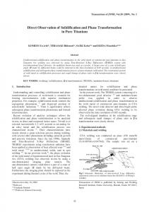
practical point of view, the Schae�er diagram can be used to predict the �nal microstructure as a function of the initial composition of the steel to be welded, the �ller metal and the dilution ratio. 16MND5 low-alloy steel and 309L stainless steel have been located on the diagram of Figure 1.4 and the composition of the resulting weld deposit necessarily lies on the straight line joining both
1
The dilution ratio corresponds to the proportion in which the base metal participates by its own melting to the elaboration of the fusion zone. 35
1.1.
Industrial context
metals.
The following microstructures have been reported for the �rst buttering layer when the
dilution is increased [18]:
•
Austenitic-ferritic with 5-6% ferrite for 20% dilution (relatively uncommon)
•
Austenitic-ferritic with a low ferrite content (around 3%) for 24% dilution (very common)
•
Purely austenitic for 30 % dilution (uncommon)
•
Austenitic with small quantities of martensite for 35 % dilution (uncommon)
•
Austenitic-martensitic for 40 % dilution (rare)
Figure 1.4: Schae�er diagram where both 18MND5 low-alloy steel and 309L stainless steel have been located [19]. Given the service conditions, the question of thermal aging naturally arises: di�erent microstructures evolve in time when subjected to temperatures around
How do these
300◦ C
for several
decades? Are the mechanical properties going to degrade? In the context of plant life extension of the French nuclear �eet, a joint EDF-AREVA engineering project has been launched in 2011 to better understand this variety of encountered microstructures, their evolution during thermal aging and their impact on the mechanical properties of the welded joint. This PhD work was intended to provide a scienti�c support for the engineering program. It is important to note that the stainless steel �ller metals formerly used to weld low-alloy steels to stainless steels have now been suppressed from the design of the new European Pressurized Reactor (EPR). They have been replaced by nickel-base alloys (Inconel 52 and 82). Such a change was motivated by the following reasons:
36
Chapter 1.
• Ease of fabrication
Introduction: industrial and scienti�c motivations
by reducing the number of intermediate layers necessary for welding
• Elimination of the martensitic layer at the fusion
line and within the FCC region during
the cooling subsequent to welding.
• Decrease of the thermal expansion mismatch: λ(16M N D5)=11.5 × 10⁻⁶ /K λ(309L)=14.4 × 10⁻⁶ /K λ(I52)=12.6 × 10⁻⁶ /K • Delay of carbon di�usion and consequently reduction of the size of the soft carbon-depleted zone in the HAZ and the hard carbon-enriched layer on the austenitic side, that may be created during the post-weld heat-treatment. In fact, the carbon solubility within the Ni-rich FCC matrix is lower than that in the Fe-rich one.
1.2 Base materials and weld production For practical reasons it has been chosen to focus this study on DMW generated by the internal cladding of the ferritic components. In fact, the low-alloy steel is protected from corrosion by two layers of stainless steel: the �rst one in 309L, the second one in 308L. The process used for the reactor pressure vessel cladding is Submerged Arc Welding. Regarding the chemical and microstructural gradients across the interface, these particular DMWs are similar to those in connections between pipes and components. Nevertheless, as the cladding does not withstand high mechanical loads, the corresponding �ller metals are not designed to have outstanding toughness properties. Therefore, the fracture properties in the austenitic stainless steel cladding which will be measured and modeled in the last part of this work cannot directly be applied to other dissimilar welds. For this study we made use of a plate of 18MND5 (EDF RD MMC id.:T248) whose dimensions
2 and 90 mm respectively. The �at strip electrode in stainless
and thickness were 630 x 1200 mm
steel was 60 mm wide and 0.5 mm thick. The chemical compositions of the materials used for this work are listed in Table 1.3.
For Al, Cr, Cu, Co, Fe, Mn, Mo, Ni, P, Si, and Ti, the contents
have been determined by X-Ray Fluorescence (XRF) on Thermo-ARL9800, whereas for C and S combustion on LECO CS230 has been used. N was analyzed by combustion and conductibility on LECO TC400. The welding parameters are indicated in Table 1.4. As can be seen in Figure 1.5, the molten pool and the arc zone are protected from atmospheric contamination by being "submerged" under a blanket of granular fusible �ux consisting of silica and other oxides and �uorides.
The coated
3
metal plate was cut to extract four pieces whose dimensions were 135 x 630 x 90 mm . One of them (id.: 248B) was kept in the as-welded condition.
The others were subjected to the post-welding
heat-treatment in order to release the internal stresses according to the following steps:
37
1.2.
Base materials and weld production
•
Charging in a cold furnace
•
Heating ramp:
•
Holding at
•
Cooling ramp:
•
Air cooling
30◦ C/h
610◦ C
for 8 hours
25◦ C/h
until
300◦ C
Among the heat-treated samples, one (id.: 248D) was put aside after the heat-treatment at whereas the two others were subjected to an accelerated isothermal aging treatment at
400◦ C:
specimen (id.: 248V1) for 5000 hours and another one (id.: 248V2) for 10000 hours.
Table 1.3: Chemical compositions of the materials
18MND5 (wt%) 309L (wt%) 308L (wt%) 18MND5 (wt%) 309L (wt%) 308L (wt%)
C
Si
Mn
Ni
Cr
Mo
Cu
0.199
0.219
1.623
0.635
0.231
0.479
0.114
0.021
0.359
1.698
12.57
23.66
0.068
0.023
0.011
0.152
1.671
10.43
20.04
0.014
0.025
S
P
Al
Co
Ti
N
Fe
0.0019
0.0048
0.028
0.011
i
ΦiB
is the value of ΦB for pure i and the term i,j ΦB represents binary interaction parameters of the order r. They are obtained by an optimization
where
ΦB
XX
represents
or
The term
procedure called assessment which takes into account the available experimental and theoretical data. It has been chosen to store the mobilities rather than the interdi�usion coe�cients because they are less numerous: n mobilities versus
(n−1)2
interdi�usion coe�cients for a n-element system.
The reduced di�usivity matrix can then be calculated from the mobilities through:
0n Dkj =
n−1 X
(δik − uk )xi Mi (
i=1 where
δik
is the Kronecker symbol and
µi
∂µi ∂µi − ) ∂xj ∂xn
(4.13)
the chemical potential of element i whose derivatives with
respect to composition require the access to thermodynamic data. That is why a kinetic database always need to be associated to a thermodynamic one.
110
Chapter 4.
Modeling coupled carbon di�usion and precipitation in dissimilar steel welds
4.1.1.3 Macroscopic models for long-range di�usion with precipitation In the problem we are dealing with in this thesis, we have to consider both a macroscopic chemical gradient for di�usion, and a local driving force for precipitation.
That is why emphasis will be
put on existing models which combine long-range di�usion and phase transformations, especially precipitates formation or dissolution in a material subjected to a carbon or nitrogen �ux.
Such
coupling is relevant in many practical cases such as carburization of Ni-Cr alloys [6, 7] or stainless steels [137, 138], gaseous nitriding [139, 120], carbon di�usion in welds between dissimilar steels [7, 140, 87, 79] and gradient sintering of cemented cutting tools [141]. The work of Bongartz [6] in order to predict the carburization of Ni-based alloys in atmospheres with a high carbon activity is pioneer in this �eld. Although it is based on the Fick's law for carbon di�usion and the kinetic and thermodynamic parameters are adjusted to �t the experimental results, its approach for combining long-range di�usion and precipitation has been retained up to now. By long-range di�usion one means that the di�usion distances in the multi-phase material are large compared to the distances between precipitates. The model consists in dividing the calculation at each time step into two parts (see Fig. 4.1): a �rst step of di�usion limited to the matrix phase followed by a step of precipitation.
In the second part, the composition at which each carbide
should appear is deduced from its equilibrium constant K and compared to the global composition after di�usion. A system of equations is then solved to obtain the carbon quantity removed from the matrix by each type of precipitate and then, a new step of di�usion can be performed. The main feature of this approach is its ability to take into account an unlimited number of carbides likely to form. For instance, Bongartz et al. forecast the precipitation of
M7 C3 , M2 C , M6 C , M23 C6
◦ and M3 C2 in alloy Ni-25Cr-12Co-10Mo carburized at 850 C for 1000 hours [6]. Not only the global carbon pro�le can be calculated but also its distribution between solid solution and precipitates. Beside simpli�ed empirical approaches [88, 142], the development of modern computational thermodynamics and kinetics has allowed building more sophisticated and realistic models as the one of Engström [7] referred to as "dispersed system simulation". It is nowadays mainly used to predict phase formation and concentration pro�les as a result of long-range interdi�usion.
The
original two-stage method of Bongartz [6] was kept for the dispersed system calculation which o�ers the advantage to rely on thermodynamic and kinetic data determined independently of the system of interest. In the di�usion step, the di�usivity in the matrix was multiplied by a labyrinth factor (taken equal to the square of the volume fraction of the precipitates
f 2)
that the di�usion paths could be partly blocked by the dispersed particles.
to include the fact In the equilibrium
step, the volume fraction and composition of each phase (matrix and precipitates) are obtained by minimization of the Gibbs free energy of the system.
The whole numerical procedure was
R
for the calculation of the
implemented into the DICTRA software [143] linked with Thermo-Calc chemical potentials, with use of appropriate databases.
111
4.1.
State of the art
Figure 4.1: Principle of the di�usion-precipitation calculation in Bongartz's model at one grid point between the times t1 and t2 [6]. This approach was successfully applied to carbides formation during the carburization of Ni-Cr alloys [7] and high-temperature di�usion of carbon in a joint between a low-alloy steel and a stainless steel [8]. In both cases good agreement with the experimental observations was found. Nevertheless such models are restricted to cases with di�usion occuring in a unique and continuous matrix phase. To treat the case of a ferritic/austenitic weld at the temperature of interest, each steel has to be placed in a separate cell with a �xed interface in between [140] (see Fig. 4.2). At each time step, a condition of local equilibrium at this interface allows �nding the common chemical potential for each element that is then applied as boundary condition for the subsequent di�usion calculation in each cell.
Figure 4.2: Di�usion couple between a low-alloy steel and a stainless steel annealed at 650◦ C for 100 h. a- Microstructure after etching. b- Results of the simulation in terms of mole fraction of carbides in the stainless steel as a function of the distance from the interface for di�erent temperatures of heat-treatment [8].
112
Chapter 4.
Modeling coupled carbon di�usion and precipitation in dissimilar steel welds
Later the homogenization approach was developed to handle di�usion in multiphase systems, especially for the case of Fe-Cr-Ni
α+γ
di�usion couples [144, 145]. The 1D space was divided
into slices in which local equilibrium holds and instead of the mobility in a single matrix phase, an e�ective mobility was obtained by averaging over all the phases in which di�usion occurs. In the lattice-�xed frame of reference the problem is therefore transformed into di�usion in an e�ective single phase governed by the following equation:
Jk = −
where
Mk , uk ,
respectively.
and
µk
1 1 ∗ ∂µk ∂µk (Mk uk ) Γ =− Vm ∂r Vm k ∂r
are the mobility, the u-fraction and the chemical potential of component k,
The local kinetic properties are determined by the choice of the function
is calculated as the average of the product
Φ)
(4.14)
over all the phases
Φ.
MkΦ uΦ k
Γ∗k
which
(transport capacity of element k by the phase
Several homogenization functions (Wiener bounds, Hashin-Shtrikman
bounds) have been implemented and are available into the software DICTRA [143].
This model
has been successful in predicting the thickness of the thin fcc layer that appears after annealing a
α + γ /γ + α
di�usion couple for 100 h at
1100◦ C
[144]. However the application of this model at
◦
lower temperatures (T σy
with
K = E n σy1−n
and the hardening exponent n, the specimen has to be indented
with two di�erent indenters, one of them being the Berkovich indenter (�rθ
= 0.033).
Afterwards
the following system of equations needs to be solved:
E n σ0.033 = σy (1 + �0.033 σy )
(5.11)
σ = σ (1 + � E )n y rθ rθ σy However friction between diamond and the specimen surface induces an increase of the normal force F that can be expressed as:
∆F µ =1+ F tanθ where
µ
is the friction coe�cient and
θ
the equivalent cone angle of the indenter. Therefore the
e�ect of friction is even more pronounced for cube corner indenter (θ indenter (θ
= 70.3◦ ).
(5.12)
= 42.3◦ )
than Berkovich
Taking a friction coe�cient of 0.15, which is a classical value for the contact
between diamond and metals, Bucaille [11] demonstrated that the e�ect of friction on the Berkovich indentation can be neglected whereas it causes an increase of the loading curvature by 16 % in the case of cube corner indentation.
Experimental set-up Nano-indentation tests were performed using the MTS XP machine equipped with three-sided diamond pyramids as tip, either Berkovich or cube corner. The tip area functions were calibrated by indentation on a fused silica reference sample. Bucaille's method with correction for friction was applied to estimate local mechanical properties in regions of the weld where tensile specimen could
150
Chapter 5.
Heterogeneities in the local elasto-plastic behavior
not be extracted (decarburized layer, martensitic band, carburized austenite). depth was set to 1
The penetration
µm and the potential residual cold working of the specimen's surface was removed
by prolonged polishing in colloidal silica suspension. Some indentations were also performed in the base metal, where the mechanical properties are known by tensile testing.
Section 5.3.1.2 will
detail the results that lead to the conclusion that the nanoindentation method for extracting plastic properties (yield strength and hardening exponent) is reasonably applicable to our material, except for the two-phase stainless steel region. The method requires each Berkovich indent to be associated with another cube corner indent to determine one set of plastic properties (σy ,n). As there exists a signi�cant scatter for the indentation curves within each group, the criterion for pairing those data was the ranking of the hardness value. The method could not be applied to the stainless steel as its microstructure made of
δ -ferrite ligaments embedded in an austenitic matrix is highly heterogeneous
at the scale of indentation and might lead to indentation size e�ects [179].
5.2.2 Processing of equivalent bulk material by decarburization experiments Because its width is limited (200
µm) and the interfaces with adjacent regions are not planar, tensile
specimens could not be extracted from the decarburized layer. The goal of this part was to �nd a way to create an equivalent bulk material to the decarburized layer in order to perform tensile tests on it. Thus this equivalent material should meet the following speci�c characteristics:
• Large ferrite grains:
mean diameter around 40
• Low carbon content: w(C) ≈ 0.015% • Soft material:
µm
without any carbides
HV1.5) is associated to a low strain which prevents fracture from happening there. On the stainless steel side (right part of the plots), the triaxiality increases gradually when increasing the strength of the carburized zone. The di�erence of behavior between both soft layers is related to the presence of constraints on only one side of the stainless steel.
Concerning the stress-strain curves, they were only slightly a�ected, but exhibited, as expected, an increase of the ultimate tensile strength when the strength of the carburized layers was increased (see Table 6.7). A decrease of the hard layers strength results in an increased ductility: up to 1.60 for the true fracture strain in the case of a 1000 MPa yield stress. However, as shown in Table 6.7, a huge increase of the strength would be necessary in the model to signi�cantly reduce the fracture strain: even with a yield point at 2000 MPa over 105
µm,
the experimentally observed value of 0.70
for the reduction of area could not be reproduced. The increase of stress triaxiality seems to be systematically counter-balanced by the displacement of the region with large strains. This explains that only small variations of the fracture strain were obtained for a yield point varying between 1200 and 2000 MPa in the carburized regions. Such an increase in yield stress cannot �nd a reasonable explanation based on physical grounds.
199
6.4.
Application of the model to ductile failure in the soft regions
Figure 6.16: In�uence of the strength of the carburized zone on a- the equivalent plastic strain, b- the stress triaxiality across the fusion line for a notch deformation of 30%. Table 6.7: In�uence of the strength of the carburized zone on the true fracture strain, the ultimate tensile strength and the failure position relative to the interface with martensite in the initial state.
True fracture strain Failure position Maximum stress σy = 1000 MPa
1.61
122
µm
615 MPa
σy = 1200 MPa
1.27
129
µm
628 MPa
σy = 1500 MPa
1.16
136
µm
637 MPa
σy = 1800 MPa
1.20
143
µm
640 MPa
σy = 2000 MPa
1.14
143
µm
641 MPa
6.4.1.5 In�uence of the plastic properties of the decarburized region Since low carbon contents are particularly di�cult to measure (see Section 3.3.1) and slight variations are known to have a drastic e�ect on the yield stress, plastic properties of the soft regions (both decarburized and intermediate zones) will be varied in this section.
Indeed, an accurate
measurement of the carbon content within the decarburized layer could only be performed by SIMS in the case of a medium-sized martensite (around 50
µm).
One could expect that a larger martensite
would result in a higher driving force for carbon to leave the low-alloy side of the weld and so create a more pronounced depletion. However, the size of the decarburized layer with large ferritic grains was found to be unchanged and equal to 200
µm
whatever the size of the adjacent martensite.
Three couples of yield points were investigated, the hardening exponent being kept constant and equal to 0.2: 200/300 MPa, 250/300 MPa and 300/350 MPa for the decarburized and intermediate layers respectively. The results in terms of true fracture strain and fracture location are displayed in Table 6.8 for two values of the nucleation stress: 1800 and 1400 MPa. 1400 MPa corresponds to the nucleation stress which allows reproducing the redution of ductility experimentally observed in the case of a 120
µm wide martensite.
Changing the yield point of the soft regions essentially a�ects
200
Chapter 6.
Investigation of the damage mechanisms in the soft regions
the location of the element where coalescence starts, with lower yield points leading to failure closer to the hard layers. However, for a given nucleation stress, the true fracture strain was only slightly modi�ed (see Table 6.8). In the case of the 200/300 MPa couple and a nucleation stress of 1800 MPa, no value could be reported as the voids never nucleated. It is due to the stress levels that were too low for the nucleation condition to be ful�lled (Equations 6.4 and 6.5).
Table 6.8: In�uence of the strength of the decarburized and intermediate zones on the true fracture strain and failure position relative to the interface with martensite in the initial state.
Nucleation stress Yield points (MPa) True fracture strain Failure position (µm)
σnuc = 1800 MPa
σnuc = 1400 MPa
200/300
250/300
300/350
200/300
250/300
300/350
-
1.13
1.21
0.57
0.72
0.74
-
136
157
114
150
157
Thus, none of the changes investigated (size of the martensite, strength of the hard layers, yield stress of the decarburized and intermediate zones) was e�cient to explain the large variations of ductility encountered when performing tensile tests on notched specimens: from 1.43 to 0.70 when the martensite's width was increased from 5 to 120
µm.
Changing the nucleation stress (from 1800
to 1400 MPa) while maintaining all other parameters constant (size and strength of the di�erent regions of the weld) was the only way to cover a wide range of ductility. However, the MnS particles, which serve as nucleation sites for damage to initiate, originate from the solidi�cation of the initial base material and are not a�ected by carbon di�usion during the heat-treatment.
There is no
physically acceptable explanation for the strength of the particles/matrix interface or the size of the particles to change with the width of the interfacial martensitic band.
The only admissible explanation for a drastic drop of the ductility when increasing the martensite's width could be that the high level of stress triaxiality would induce nucleation in other sites that were not considered here, such as triple junctions of grain boundaries or small impurities. These supplementary sites could be activated only under high stress levels that are reached in the vicinity of the martensitic band, especially when its width is signi�cant. Thus it could lead to premature failure without a need for a signi�cant growth of cavities. This argument is in agreement with the fracture surfaces of Figure 6.4 where the voids are more numerous and smaller in the case of the 120 µm wide martensite.
201
6.4.
Application of the model to ductile failure in the soft regions
6.4.2 Ductile failure in the stainless steel 6.4.2.1 Two populations of inclusions Contrary to the case of the decarburized zone with few nucleation sites, the stainless steel layers contain many inclusions that can serve to initiate damage. The main nucleation sites are the oxides as they can reach sizes of several micrometers and present a large mismatch of properties with the metallic matrix.
The
δ -γ
interfaces are also known to be prone to damage initiation [215]
as the di�erence in phase properties in�uences the local stress triaxiality which serves as driving force for interface decohesion [216].
In the case of the heat-treated sample, these interfaces are
certainly weakened as they are decorated by an important density of carbides, which will enhance void nucleation.
It is thus necessary to consider two populations of voids, each of them being
characterized by an initial volume fraction and a critical nucleation stress.
For the void aspect
ratio, a rule of mixture was applied [202]:
W0 =
f0A W0A + f0B W0B f0A + f0B A
Although both particles are quasi-spherical (W0
= W0B = 1),
(6.21)
the voids at the carbides will appear
later (higher critical nucleation stress), with a global void aspect ratio being higher than 1 because the primary voids nucleated on the oxides will have already elongated in the loading direction. For this reason, it was necessary to transform the initial porosity of the second population into an e�ective porosity [202]:
f0B,ef f =
W B f W0B 0
(6.22)
where W corresponds to the value of the void aspect ratio at the nucleation strain. The e�ective porosity
f0B,ef f
is then used in Equation 6.21.
6.4.2.2 Results in terms of fracture strain In this section, we will consider ductile failure of �at tensile specimens machined either perpendicular to the fusion interface and including the entire weld or parallel to it in a given stainless steel layer. In order to trigger necking in the simulation of homogeneous tensile specimens a small initial width reduction (linear over 0.75 mm with a maximum reduction of 2% at mid-width) was introduced in the cross-section located on the symmetry plane of the sample. As shown in Figure 6.17, the absence of both notch and con�nement led to triaxiality values in the stainless steel lower than those previously encountered in the decarburized layer. The di�culty of predicting ductile failure in metallic alloys with di�erent kinds of particles lies in the determination of the appropriate nucleation stress for each family of inclusions. In the present study, we decided to optimize these values for the case of an homogeneous 308L tensile specimen machined parallel to the fusion interface in both the as-welded and heat-treated states (see stress-strain curves of Fig. 5.16-c). The selected values for each nucleation sites are reported in Table 6.9. As cavities along the
δ -γ
interfaces were also observed in the as-welded state of the 308L
sample, the possibility of nucleating voids in this region, even in the absence of carbides, had to be
202
Chapter 6.
Investigation of the damage mechanisms in the soft regions
considered. Of course, the weakening e�ect of the
M23 C6
particles present at the
δ -γ
boundaries
in the post-weld heat-treated condition, was taken into account by lowering the nucleation stress (from 3000 to 2300 MPa) at this location and so allowing voids to appear earlier in the course of deformation. Among the di�erent sources of voids, the oxides, which present both a large size and a high crystallographic mismatch with the matrix, were the �rst to be activated (σnuc
= 1500
MPa).
Figure 6.17: Stress triaxiality as a function of equivalent plastic strain for the element located in the center of the most damaged region in �at tensile specimens. Table 6.9: Values of the nucleation stress used in the damage model for each site.
Nucleation stress Oxides
1500 MPa
δ -γ
3000 MPa
As-welded
interfaces
Carbides in the heat-treated state
2300 MPa
Once the nucleation stresses were selected, the damage model was then applied to predict ductile failure in homogeneous 309L specimens in both the as-welded and heat-treated states and in the complete weld (heterogeneous sample with the loading axis perpendicular to the fusion interface). The results in terms of macroscopic fracture strain are summarized in Table 6.10. The reduction of ductility due to the post-weld heat-treatment is correctly reproduced and there is a good agreement for both the homogeneous specimens and the complete weld. Higher ductility is predicted in the 309L samples than in the 308L ones, as expected given both a lower volume fraction of inclusions and a larger hardening capacity. As the constitutive laws for all the di�erent regions of the weld were not precisely known in the as-welded state, the same triaxiality history as in the heat-treated state was applied to the damage model when dealing with the as-welded state of the entire weld. Only the inclusions were adapted to correspond to the ones quanti�ed in the as-welded 308L. Despite this approximation, the agreement between experimental and simulated fracture strains is good (around 1.5). It is also important to note that the damage calculation for the weld sample in the as-welded state led to coalescence before the maximum principal stress at
203
6.4.
the
Application of the model to ductile failure in the soft regions
δ -γ
had reached the critical value of 3000 MPa. Therefore voids could not nucleate at the
interfaces whereas they appear in the homogeneous 308L and 309L samples before failure.
δ -γ
This
is in agreement with the fact that no elongated cavities were observed on the fracture surface of the as-welded assembly whereas they were present in the case of 308L and 309L samples in the as-welded condition. It can also explain the higher ductility (1.5 versus 1.27 and 1.25) obtained for the weld than for the longitudinal and homogeneous specimens.
Table 6.10: Comparison between experimental tensile tests and damage modeling in terms of true fracture strain.
True fracture strain �f exp. �f sim. 308L as-welded 308L heat-treated 309L as-welded 309L heat-treated Weld as-welded Weld heat-treated
204
1.27
1.35
1.00
1.10
1.25
1.39
1.10
1.23
1.50
1.55
1.10
1.21
Chapter 6.
Investigation of the damage mechanisms in the soft regions
6.5 Conclusion This chapter dedicated to damage mechanisms has been focused on the two soft regions of the weld (yield points lower than 300 MPa) that were identi�ed in Chapter 5: the stainless steel layers and the decarburized zone. Both regions are subjected to transformations during the post-welding heat-treatment:
• The decarburized layer corresponds to a 200 µm wide region of the HAZ of the base metal subjected to
•
carbides dissolution, carbon depletion and grain growth.
austenitic cladding layers contain ferrite residuals which lead to the formation of carbides at the δ - γ interfaces.
The
decompose at
610◦ C
and
Flat tensile specimens were su�cient to study damage in the stainless steels whereas notches had to be machined on the weld to force failure to occur in the narrow decarburized layer. The main di�erences between both regions are the
nucleation sites.
con�nement degree
and the
quantity of potential
The latter are numerous in the stainless steels, especially in the heat-treated
state where the carbides present along the
δ
-
γ
interfaces complement the oxides formed during
the solidi�cation of the weld. On the contrary, the decarburized region is rather "clean" with only few and small MnS inclusions that can serve as nucleation sites. 3D elasto-plastic calculations allowed to evaluate the levels of plastic deformation and stress triaxiality within the di�erent regions of interest. In addition, a
model
micro-mechanics based damage
was applied to the critical element of the mesh in the di�erent con�gurations in order to
predict the true fracture strain. This model, where the critical stress for voids nucleation is the only
quantitatively predict the reduction of ductility observed in the stainless steel layers after heat-treatment due to the weakening e�ect of the carbides on the δ - γ interfaces. However, in the case of the decarburized zone, it failed in reproducing the variation of true fracture strain with the width of the adjacent martensitic layer. adjustable parameter, allowed to
As expected, higher levels of stress triaxiality were obtained in the case of a large hard zone but they were limited to a band of 70
µm adjacent to the martensite and associated with a small plastic strain.
This was responsible for a displacement of the failure location towards the base metal where both plastic strain and triaxiality were weakly in�uenced by the size of the martensitic band. A detailed parametric study was carried out (strength of hard and soft zones especially) but none of the sets of parameters within a reasonable range of variations led to su�ciently large changes in ductility as observed experimentally. Nucleation on other sites in the case of high stress levels (large martensite) was invoked to explain the drop of ductility measured experimentally. An extended experimental campaign would be necessary to con�rm the tendency observed, especially on thicker samples such as compact tension specimens.
205
6.5.
Conclusion
206
Chapter 7
Conclusions The dissimilar steel welds between a low-alloy steel and a stainless steel are widely encountered in industrial applications. They are known to be the place of several complex phase transformations that occur in the vicinity of the dissimilar interface during fabrication and/or service.
Both
these microstructural evolutions and their potential consequences on the mechanical behavior of the assembly were still poorly understood.
That is why further studies were necessary to
accurately quantify the extent of these evolutions and become able to predict their e�ects on both microstructure and mechanical properties.
7.1 Overview of the work This PhD thesis has been divided into three main parts, each of them corresponding to a di�erent condition of the weld, that is to say the as-welded state, the post-weld heat-treated one and the one in service.
• Part I
solidi�cation of the dissimilar interface and the origin of the resulting microstructures. Microstructural observations (OM, SEM, WDS, EBSD) was dedicated to the
were combined with thermo-kinetics calculations. the metastable
γ
The main objective was to explain why
phase formed in a narrow layer (≈
70 µm)
from the base metal and how
two successive transitions in the solidi�cation mode allowed to recover the
δ -γ
microstructure
typical of austenitic stainless steels.
• Part II
was focused on the
heat-treatment
phase transformations
that occur during the
post-weld
◦ at 610 C. The latter were the subject of an in-depth investigation, both
experimentally and theoretically. First, several characterization techniques were associated in order to:
�
measure the carbon di�usion through the weld (WDS, SIMS).
�
identify the precipitates that form in the carburized regions (ACOM-TEM) together with their preferential nucleation sites (FEG-SEM, TEM).
207
7.2.
Speci�c contributions
�
quantify the carbides in terms of volume fraction, number density and size as a function of their distance from the fusion line (FIB serial cutting, TEM).
�
measure the precipitates composition (EDX-TEM) as well as the chemical elements solubility within the matrix phases (APT).
Then, in a second chapter, a
mesoscopic thermodynamic and kinetics model developed
to fully couple di�usion in a multi-component system with precipitates nucleation, growth and coarsening was presented. The numerical Kampmann-Wagner approach was adopted for precipitation whereas the Onsager's equation with the chemical potential as driving force was used for calculating long-range di�usion. A parametric study allowed understanding the role played by each microstructural feature in the carbon transfer from the base metal towards the weld. The conditions necessary for an extensive carburization of the austenitic part of the weld in agreement with the experimental measurements were highlighted.
• Part III
was intended to investigate how the phase transformations that occur during the
local mechanical behavior around the dissimilar �rst chapter was to determine a constitutive law (yield
post-weld heat-treatment impact the
interface.
The purpose of the
stress and hardening capacity) for each type of microstructure encountered in the vicinity of the fusion line. For that, several experimental techniques were used (micro-tensile specimens, nanoindentation) and a particular attention was paid to the decarburized layer with two trials aiming at creating an equivalent bulk material. Digital image correlation at the micro-scale allowed validating the mechanical behavior chosen for each region.
Ductile failure
in the
two soft regions (stainless steel and decarburized layer) was the topic of the second chapter. Experimental observations were combined with a micro-mechanics based damage model to identify the mechanisms that may cause a loss of ductility of the weld.
7.2 Speci�c contributions The
salient
features
of
this
study,
that
provide
new
inputs
for
the
understanding
of
the
microstructural and mechanical evolutions of the dissimilar steel welds, are listed below:
• In�uence of the �uid �ow in the weld pool A region of compositional gradients was detected by WDS on the weld metal side. Segregations during solidi�cation were calculated and were found to be insu�cient to create such an extended gradient. Insu�cient mixing of the molten base metal with the liquid weld metal was pointed out as the cause of the compositional heterogeneities. Therefore, the �uid �ow in the weld pool, and consequently the welding parameters were evidenced as responsible for the diversity of the microstructural features encountered at the fusion line, especially the variable width of the martensitic layer.
As shown by the tensile tests on notched samples, these
particular features at the interface stemming from the solidi�cation, may play a signi�cant role when dealing with ductile failure in the decarburized layer.
208
Chapter 7.
Conclusions
• Origin of the purely austenitic zone The purely austenitic zone had already be mentioned as a common feature in the dissimilar welds between a ferritic low-alloy steel and an austenitic stainless steel.
However no clear
explanation had been given so far for its formation. In this study, it was proven that this 100
µm wide zone resulted from the metastable solidi�cation of the weld as primary austenite and that this out-of-equilibrium solidi�cation took place in epitaxy on the solid base metal: such �ndings imply the metastable fusion of the base metal.
• The post-weld heat-treatment cannot be assimilated to a simple temperature
plateau The post-weld heat-treatment is often, but wrongly, designed by its holding time at
610◦ C.
◦
However the heating and cooling rates being low (30 C/h), the assembly spends a signi�cant amount of time at intermediate temperatures (between 400 and 610
◦ C) where changes can
occur at the scale of the microstructure. The study of an intermediate sample, for which the heat-treatment had been interrupted at the end of the heating ramp, has shown that some carbon di�usion from the base metal to the martensitic layer has already taken place before the temperature plateau. This di�usion was accompanied by precipitates nucleation and growth together with carbon segregation to the subgrain boundaries within the tempered martensite.
◦
It would be a mistake to limit the post-weld heat-treatment to a temperature plateau at 610 C and not to consider the e�ects of the lower temperatures on the weld microstructure.
• Model coupling long-range di�usion to precipitation kinetics Up to now, modeling carbon di�usion within a dissimilar steel weld was always achieved under the hypothesis of equilibrium precipitation. In the present case, this classical approach was unable to reproduce the carbon pro�le measured through the weld, especially the extent of the carbon di�usion in the austenite. To face this problem, a model combining precipitation kinetics to long-range di�usion was built. Its speci�city lies in:
�
the
use
of
Calphad-type
databases
to
calculate
the
thermodynamic
and
kinetics
parameters at each node and each time step.
�
the consideration of the chemical potential gradient instead of the concentration gradient as the driving force for precipitation.
�
the calculation of the full precipitates distribution at each node via a numerical Kampmann-Wagner approach instead of only the mean radius.
�
the possibility of taking into account several types of precipitates that may compete against each others together with the dissolution of some of them.
�
the estimation of the interfacial energy of the precipitates through the GNNBB approach.
Such a model can be applied to di�erent combinations of alloys involved in a di�usion couple but also to heat-treatments in a gaseous atmosphere such as in nitriding and carburizing processes.
209
7.2.
Speci�c contributions
• Role of the martensitic layer in the carbon di�usion from the low-alloyed side to
the high-alloyed one The accumulation of carbon within the interfacial martensitic layer has been found to be responsible for carbon penetration over 70
µm
within the austenitic weld metal.
The
experimental measurements together with the thermo-kinetics modeling have shown the dual nature of this region: on the one hand, part of the carbon precipitates and gives rise to large carbides; on the other hand, signi�cant quantities of carbon remain in solid solution and are available to di�use towards the austenite. For the modeling to reproduce experimental measurements, it has been necessary to destabilize the Cr-rich carbides via the elastic stresses to enable the dissolution of a su�cient amount of carbon within the matrix.
• Ageing of the dissimilar interface The study of the samples aged at
400◦ C
for 5000 and 10000 hours has revealed the stability
of both the microstructure and the mechanical properties of the dissimilar weld in service conditions.
Thus the post-weld heat-treated state has been considered as representative of
the weld that would be encountered in today's nuclear power plants. That is why the whole mechanical study (Part III) has been focused on this state.
More details concerning the
microstructural and mechanical investigations that were conducted on aged samples can be found in Appendix B.
• δ -ferrite decomposition at 610◦ C and signi�cant consequences on the weld
ductility The dissimilar steel welds are the only welds of a pressurized water reactor involving austenitic stainless steels to be post-weld heat-treated. Microstructural observations at di�erent scales have evidenced the decomposition of the
◦ at 610 C. As a result, the
δ -γ
δ -ferrite residuals into austenite and M23 C6
carbides
interfaces in both 309L and 308L cladding layers are decorated
by cuboïd carbides which constitute potential sites for voids nucleation. A drop of ductility associated with the presence of elongated voids on the fracture surface has been found when comparing the weld in the heat-treated state to the one in the as-welded condition. weakening e�ect of the carbides on the
δ -γ
The
interfaces has been taken into account and the
damage model was able to reproduce the order of magnitude of the decrease in fracture strain.
• Microstructural and mechanical characterization of the decarburized region Although
generally
associated
with
a
low
hardness
and
the
absence
of
carbides,
the
decarburized layer that exists on the low-alloy side of a dissimilar steel weld was poorly documented both in terms of microstructural and mechanical characteristics. In the present study, a quantitative method using reference samples with a known carbon concentration has been developed in SIMS in order to estimate the low carbon content of the decarburized layer.
Concentrations between 0.0043 and 0.02 wt.% have been detected within the large
grains ferritic region. Then, equivalent bulk materials with similar microstructure and carbon
210
Chapter 7.
Conclusions
content were fabricated in two di�erent ways: by decarburization of the base metal in wet
H2
atmosphere and by heat-treatment of di�usion couples obtained by HIP. This allowed
accurately determining the mechanical properties of this particular region: yield stress of 200 MPa and hardening exponent of 0.2. A thorough knowledge of the properties and behavior was achieved through this work and can now be used for other studies involving dissimilar steel welds, especially numerical simulations.
• Clear evidence of an intermediate zone between the decarburized region and the
una�ected base metal The decarburized layer which results from the carbon depletion of the base metal was often associated with the 200
µm
wide ferrite layer adjacent to the fusion line. However meticulous
carbon measurements by both WDS and SIMS have shown that the carbon depletion actually extends over 500 to it.
µm,
which include the region with large ferritic grains but are not limited
The supplementary 300
µm
correspond to a gradual decrease of the carbon content
from the one of the base metal (0.2 wt.%) to about 0.015 wt.%. In this intermediate zone, some carbides are still present. On a mechanical point of view, this zone, also highlighted by DIC, was subjected to intermediate levels of strain during tensile testing.
A yield point of
300 MPa together with a hardening exponent of 0.2 have been attributed to it. This region is of particular importance as it directly acts on the soft ferritic region and allows to reduce its con�nement degree and consequently its triaxiality.
7.3 Perspectives Several new aspects have been raised but could not be addressed in this study due to time constraints.
It would be of great interest to include them if an extension of the present work
is considered. Therefore some future tasks will be suggested below to complement the three topics that have been investigated in this PhD thesis.
7.3.1 Solidi�cation of the dissimilar interface • In�uence of the nature of the base metal on the formation of the purely austenitic
zone: It was shown that the metastable fusion of the 18MND5 base metal was responsible for the solidi�cation of the weld as primary austenite in the �rst 100 to replace the 18MND5 by another base metal with a range of temperatures in its phase diagram.
µm.
It would be of great interest
δ -ferrite domain spreading over a larger
This means choosing an alloy with a higher
content in ferrite stabilizer elements (Cr,Mo) and/or a lower content in austenite stabilizer elements (C,Ni,Mn).
And this should result in eliminating the metastable melting of the
substrate and consequently lead to a primary ferrite solidi�cation of the weld over its entire height. Such experiment would constitute a direct evidence to con�rm the scenario we have proposed in Part I.
211
7.3.
Perspectives
• E�ect of the welding speed on the metastable melting of the base metal: A Time-Resolved X-Ray Di�raction (TRXRD) experiment was conducted in a synchrotron to study the in�uence of the heating rate on the nature of the 18MND5 melting. It aimed at determining a critical heating rate above which the melting would be metastable and proceed in only one step (γ
→Liquid)
without any
δ -ferrite
formation.
However several technical
di�culties were encountered (reproducibility of the high rate temperature cycles, failure of the sapphire crucibles, carbon evaporation, grain growth) and prevented us from drawing unambiguous conclusions. It would be necessary to improve the experimental set-up to achieve the initial goal and completely validate the hypothesis of a metastable melting at high heating rates.
• Multi-physics modeling of the submerged arc welding process: The thickness of the boundary layer was estimated by simple and approximate calculations (see Section 2.4.1 and Appendix A for more details). Yet a good order of magnitude similar to the extent of the region with compositional gradients measured by WDS was obtained. To go further, it would be interesting to build a multi-physics model to accurately calculate the �uid �ow in the weld pool and its consequences on the mixing of the elements from the �ller metal with the molten base metal under both convection and di�usion. A parametric study based on the welding characteristics could allow optimizing the mixing and proposing di�erent solutions to reduce the extent of the intermediate mixed zone. Up to now, no numerical model has been developed to simulate dissimilar welding by SAW.
7.3.2 Phase transformations during the post-welding heat-treatment • Improvements of the carbon measurements: This study had to cope with the di�culty of measuring low carbon contents in regions of reduced size.
In-depth pro�les with SIMS were successful to quantify carbon within the
decarburized layer of the heat-treated sample but failed in the case of the as-welded specimen because of their limited lateral resolution. A quantitative approach with SIMS in the image mode (area of
100 × 100 µm2 )
Lippman in Luxembourg.
is currently under development at the Centre Public Gabriel
It should enable in a near future a quanti�cation of both the
decarburization and carburization which take place during the welding process.
Moreover
APT measurements could also be performed in the decarburized regions in order to determine how the residual carbon is distributed within the matrix and evaluate the level of segregations at the grain boundaries.
212
Chapter 7.
Conclusions
• Simpli�cation of the di�usion/precipitation problem: Modeling the coupling between long-range di�usion and precipitation turned out to be far more di�cult than initially expected.
The di�culty arose from the non-isothermal heat-
treatment, the complexity of the three-phase con�guration of the weld with the presence of an intermediate layer of martensite at the interface, and the phase competition between several precipitates. To correctly assess the validity of the model developed, it would be particularly relevant to test it on simple cases, for which experimental data will thus be needed. Di�usion couples could be realized by HIP and subjected to various isothermal heat-treatments.
As
the alloys in contact will not melt, mixing of elements will only occur by solid-state di�usion, preventing from the formation of any extended IMZ and its subsequent transformation into martensite.
By varying the duration of the heat-treatment and/or the composition of the
alloys, di�erent states in terms of decarburization and carburization could be achieved. However an extensive characterization campaign would be necessary to quantify not only the carbon evolution through the weld but also the nature and characteristic parameters of the precipitates.
Then, the simulation could be extended to more sophisticated situations,
including the e�ect of the thickness of the intermediate martensitic layer.
• A better thermodynamic and kinetics description of the tempered martensite: Despite
a
signi�cant
chromium
content
(around
11
wt.%),
high
levels
of
carbon
in
supersaturation within the matrix of the tempered martensite (around 0.1 wt.%) were measured by APT in the as-welded, intermediate and heat-treated states. In the modeling step, it was necessary to highly destabilize the precipitates to maintain such a large quantity of dissolved carbon. This enhanced solubility turned out to be the key parameter allowing carbon to di�use within the austenitic part of the weld. These �ndings give strong hints that the current description of the tempered martensite as an alloyed BCC phase is certainly not correct. For the moment no speci�c thermodynamic and kinetics database has been developed for such microstructures.
In the present case, the speci�c and dual role of the subgrain
boundaries as both shortcuts for di�usion and segregation places allowing precipitates to nucleate and grow has been highlighted. Fischer et al. [217] have proposed a new approach to deal with trapping of di�using interstitial components by dislocation cores, substitutionnal impurities or other sorts of traps such as incoherent interfaces.
Their method based on
local thermodynamic equilibrium between the atoms on the di�erent lattice positions and the derivation of a non-linear di�usion equation is currently under implementation in the MatCalc software. It was already shown to greatly reduce cementite precipitation in steels with a large dislocation density. A critical step in the improvement of the current model of di�usion/precipitation in a dissimilar steel weld would be to include trapping in the tempered bainitic and martensitic parts of the weld, especially at the lath boundaries. The enthalpy of this kind of traps and its evolution with the temperature should be determined and combined with an enhanced di�usion coe�cient along them.
213
7.3.
Perspectives
7.3.3 Mechanical behavior of the dissimilar weld • E�ect of the residual stresses: The residual stresses resulting from non-uniform heat distributions and phase transformations within the assembly during welding can have a signi�cant impact on both di�usion and precipitation as well as on mechanical behavior.
Finite element simulations [191] showed
that the post-weld heat-treatment of the dissimilar weld was e�cient at reducing the level of stresses within the HAZ but did not have any e�ect on the cladding layer that are found to be in tension. However these calculations were performed with a coarse mesh (element size around 1 mm) which did not allow capturing �ne evolutions in the vicinity of the fusion line. Measurements at the micron scale, by means of either neutron di�raction in a synchrotron or FIB milling and image correlation in a SEM, would certainly be interesting to evaluate the levels of residual stresses with a �ne lateral resolution adapted to the size of the microstructures around the dissimilar interface.
• Mechanical behavior of the di�erent regions at large strains: Tensile testing on micro-samples were mainly used to determine the constitutive laws that characterize each region of the weld. However such method only gives valuable information up to the onset of necking. When dealing with failure, high levels of strain can be achieved locally and it becomes necessary to extrapolate the previously determined laws. An e�cient way to assess the mechanical behavior at large strains would be to perform compression or torsion tests on samples extracted from the di�erent regions of the weld.
• Anisotropic mechanical behavior of the stainless steel cladding layers: The anisotropic behavior of the stainless steel cladding layers has been evidenced by tensile testing in di�erent directions.
Not only the yield point was found to vary in the di�erent
directions, but also the hardening capacity appeared to be anisotropic. To correctly take into account this speci�city into the elasto-plastic modeling, it would be necessary to calculate the constitutive law in the transverse direction using a crystal plasticity model together with an homogenization scheme. Indeed the thickness of the cladding layers is too small (4 mm) to machine a tensile specimen in it. The Von Mises yield criterion would have to be replaced by the Hill one. Anisotropy of the mechanical properties is also known to in�uence the cavity growth in ductile failure [200] and this aspect was not considered in the present study.
• Correction of the out-of-plane displacements near the dissimilar interface: In order to accommodate the mechanical mismatch that exists between the carburized and decarburized regions in the heat-treated sample, signi�cant out-of-plane displacements occurred at the fusion line during tensile testing on the entire weld.
Such out-of-plane
displacements that were con�rmed by pro�lometry prevented from a correct measurement of the local strains in the decarburized region near the hard martensite by 2D image correlation. It would be �rst necessary to scan the specimen's surface by pro�lometry after each increment
214
Chapter 7.
Conclusions
of strain and then, similarly to what was done in [218], to recalculate the deformation gradient according to the real out-of-plane displacements and deduce the exact value of the in-plane strain components. Such correction would allow a complete comparison of the levels of strain obtained by simulation and experimental measurements, even at the fusion line.
• Critical stress for voids nucleation: The critical stress for voids nucleation is the main adjustable parameter of the damage model. Its value was evidenced to have a profound e�ect on the �nal fracture strain.
Combining
elasto-plastic �nite element simulations with interrupted tensile tests on notched specimens would allow assessing this critical value for the various types of particles encountered in the di�erent regions of the weld [14].
Concerning the decarburized region, MnS particles were
considered in this study as the main damage initiation sites.
However the level of stress
triaxiality could have a pronounced e�ect on cavity nucleation that could initiate at multiple locations, especially at grain boundary triple junctions. Interrupted tensile tests could also be suggested as a way to address this point and remove uncertainty on that topic.
• Supplementary mechanical testing and modeling in the decarburized layer: The e�ect of the martensitic layer on the ductility of the decarburized region that was experimentally observed could not be reproduced by damage modeling. This point �rst needs con�rmation, which requires an extensive experimental campaign. Thoughness measurements by means of Compact Tension specimens with a fatigue crack located within the decarburized region could be suggested to experimentally assess the ease for a crack to propagate within this con�ned region.
Tests at
300◦ C
would also be necessary to mimic the conditions of
service. If the tendency for ductility loss is experimentally con�rmed, the modeling approach will have to be improved.
For failure in the decarburized region to be in�uenced by the
size of the martensitic layer, it has to take place in the vicinity of the fusion line.
It was
not the case in the present simulations based on the well-known Gurson model, in which both stress triaxiality and plastic deformation govern the growth of cavities. Second-gradient models [219, 220] including the gradient of stress as driving force for damage development might be more adapted to cause failure in the vicinity of the interface, as it was observed experimentally. However such models are computationally expensive and convergence of the elasto-plastic iterations often remains di�cult.
215
7.3.
Perspectives
216
Bibliography
217
Bibliography [1] C. Cayron, B. Artaud, and L. Briottet.
Reconstruction of parent grains from EBSD data.
Materials Characterization, 57:386�401, 2006. [2] C. Cayron. ARPGE: a computer program to automatically reconstruct the parent grains from electron backscatter di�raction data.
Journal of Applied Crystallography,
pages 1183�1188,
2007. [3] W. Kurz, B. Giovanola, and R. Trivedi. Theory of microstructural development during rapid solidi�cation.
Acta Metallurgica, 34:823�830, 1986.
[4] M. Bobadilla, J. Lacaze, and G. Lesoult.
In�uence des conditions de solidi�cation sur le
droulement de la solidi�cation des aciers inoxydables austnitiques.
Journal of Crystal Growth,
89:531�544, 1988. [5] M.
Rappaz,
S.A.
David,
J.M.
Vitek,
and
L.A.
microstructures in Fe-Ni-Cr single-crystal welds.
Boatner.
Analysis
of
solidi�cation
Metallurgical Transactions A,
21A:1767�
1782, 1990. [6] K. Bongartz, W. Quadakkers, R. Schulten, and H. Nickel. A mathematical model describing carburization in multielement alloy systems.
Metallurgical and Materials Transactions A,
20:1021�1028, 1989. [7] A. Engström, L. Höglund, and J. Ägren. systems.
Computer simulation of di�usion in multiphase
Metallurgical and Materials Transactions A, 25:1127�1134, 1994.
[8] T. Helander, J. Ägren, and J-O. Nilsson.
An experimental and theoretical investigation of
di�usion across a joint of two multicomponent steels.
ISIJ international, 11:1139�1145, 1997.
[9] J. Svoboda, F.D. Fischer, P. Fratzl, and E. Kozeschnik.
Modeling of kinetics in multi-
component multi-phase systems with spherical precipitates I- Theory.
Materials Science and
Engineering A, 385:166�174, 2004. [10] E. Kozeschnik.
Modeling solid-state precipitation.
Momentum Press, 2013.
[11] J.L. Bucaille, S. Stauss, E. Felder, and J. Michler. Determination of plastic properties of metals by instrumented indentation using di�erent sharp indenters. 2003.
219
Acta Materialia, 51:1663�1676,
Bibliography
[12] T. Pardoen and J.W. Hutchinson.
An extended model for void growth and coalescence.
Journal of the Mechanics and Physics of Solids, 48:2467�2512, 2000. [13] T. Pardoen and J.W. Hutchinson.
Model for trends in toughness of ductile metals.
Acta
Materialia, 51:2467�2512, 2003. [14] F.M. Beremin. Cavity formation from inclusions in ductile fracture of A508 steel.
Metallurgical
Transactions A, 12:723�731, 1981. [15] A.L. Gurson. Continuum theory of ductile rupture by void nucleation and growth: Part IYield criteria and �ow rules for porous ductile media.
Journal of Engineering Materials and
Technology, 99:2�15, 1977. [16] P.F. Thomason.
Ductile fracture of metals.
Pergamon Press, 1990.
[17] www.nrc.gov. [18] B. Yrieix. Caractéristiques mécaniques locales des liaisons bimétalliques 16MND5/309L/308L. Technical report, EDF R&D HT-42/95/028/B, 1996. [19] K. Easterling.
Introduction to the Physical Metallurgy of Welding.
Butterworth-Heinemann,
1992. [20] R.L. Klueh and J.F. King. Austenitic stainless steel - ferritic steel weld joint failures.
Welding
Journal, 61:302�311, 1982. [21] J.N Dupont and C.S. Kusko. dissimilar alloy welds.
Technical note :
martensite formation in austenitic/ferritic
Welding Journal, pages 51�54, 2007.
[22] Z. Sun and T. Moisio. Weld metal/ferritic steel interface in laser welded austenitic/ferritic dissimilar steel joints.
Journal of Materials Science Letters, 13:802�805, 1994.
[23] F. Ornath, J. Soudry, and B.Z. Weiss. Weld pool segregation during the welding of low alloy steels with austenitic electrodes. [24] T. Doody.
Welding Journal, 60:227�230, 1981.
Intermediate mixed zones in dissimilar metal welds for sour service.
Welding
Journal, 55:55�60, 1992. [25] N. Murugan and R.S. Parmar. E�ect of welding conditions on microstructure and properties of type 316L stainless steel submerged arc cladding.
Welding Research Supplement,
pages
210s�217s, 1997. [26] W.F. Savage, E.F. Nippes, and E.S. Szekeres. A study of weld interface phenomena in a low alloy steel.
Welding Journal, 55:s260�s268, 1976.
[27] Y. Cui, C.L. Xu, and Q. Han.
E�ect of ultrasonic vibration on unmixed zone formation.
Scripta Materialia, 55:975�978, 2006. 220
Bibliography
[28] R. Dehmolaei, M. Shamanian, and A. Kermanpur. E�ect of electromagnetic vibration on the unmixed zone formation in 25Cr-35Ni heat resistant steel/alloy 800 dissimilar welds.
Materials
Characterization, 59:1814�1817, 2008. [29] S. Kou and Y.K. Yang. Fusion-boundary macrosegregation in dissimilar-�ller welds.
Welding
Journal, 86:303�312, 2007. [30] G. Faber and T. Gooch. Etat de la question.
Assemblages soudntre aciers inoxydables et aciers faiblement alli
Soudage et Techniques connexes, pages 109�115, 1983.
[31] H. Ikawa, S. Shin, M. Inui, Y. Takeda, and A. Nakano. On the martensitic-like structure at weld bond and the macroscopic segregation in weld metal in the welded dissimilar metals of
α-steels
and
γ -steels.
IIW Database, pages 1�33, 1972.
[32] T. Ishida. Formation of stainless steel layer on mild steel by welding arc cladding.
Journal of
Materials Science, 26:6431�6435, 1991. [33] Y.K. Yang and S. Kou.
Weld-bottom macrosegregation caused by dissimilar �ller metals.
Welding Journal, 86:379s�387s, 2007. [34] T. Gandhi and D.K. Aidun. E�ects of enhanced convection on the microstructure of dissimilar welds. In
Proceedings of the 7th International Conference, 2005.
[35] M.F. Gittos and T.G. Gooch. The interface below stainless steel and nickel-alloy claddings.
Welding Research Supplement, pages 461s�472s, 1992. [36] F. Gauzzi and S. Missori. joints.
Microstructural transformations in austenitic-ferritic transition
Journal of Materials Science, 23:782�789, 1988.
[37] T.G. Kravtsov, V.I. Ikonnikov, and N.K. Solyanik. Structure of the metal in the fusion zone in depositing austenitic steel on pearlitic steel.
[38] C.
Pan,
R.
Wang,
and
J.
Gui.
Direct
austenitic/carbon steels welded joint.
Welding International, 3:200�202, 1989.
TEM
observation
of
microstructures
of
the
Journal of Materials Science, 25:3281�3285, 1990.
[39] K. Rajasekhar, C.S. Harendranath, R. Raman, and S.D. Kulkarni. Microstructural evolution during solidi�cation of austenitic stainless steel welds metals: electron microprobe analysis study.
a color metallographic and
Materials Characterization, 38:53�65, 1997.
[40] J.C. Lippold and W.F. Savage. Solidi�cation of austenitic stainless steel weldments: Part 2 - The e�ect of alloy composition on ferrite morphology.
Welding Research Supplement, pages
48s�58s, 1980.
[41] N. Suutala. E�ect of solidi�cation conditions on the solidi�cation mode in austenitic stainless steels.
Metallurgical Transactions A, 14:191�197, 1983. 221
Bibliography
[42] J.M. Vitek, A. Dasgupta, and S.A. David. Microstructural modi�cation of austenitic stainless steels by rapid solidi�cation.
Metallurgical Transactions A, 14:1833�1841, 1983.
[43] W.T. Delong. Ferrite in austenitic stainless steel weld metal.
Welding Journal, 52:273s�286s,
1974. [44] J.A. Dantzig and M. Rappaz.
Solidi�cation.
[45] S. Fukumoto and W. Kurz. The
δ
to
γ
EPFL Press, 2009.
transition in Fe-Cr-Ni alloys during laser treatment.
ISIJ International, 37:677�684, 1997. [46] S. Fukumoto and W. Kurz. Prediction of the during laser treatment.
δ
to
γ
transition in austenitic stainless steels
ISIJ International, 38:71�77, 1998.
[47] T. Hashimoto, H. Terasaki, and Y. Komizo. solidi�cation process of alloy tool steel.
E�ect of the solidi�cation velocity on weld
Science and Technology of Welding and Joining,
13:409�414, 2008. [48] S.S. Babu, J.W. Elmer, J.M. Vitek, and S.A. David.
Time-resolved X-ray di�raction
investigation of primary weld solidi�cation in Fe-C-Al-Mn steel welds.
Acta Materialia,
50:4763�4781, 2002. [49] T.W. Nelson, J.C. Lippold, and M.J. Mills. Nature and evolution of the fusion boundary in ferritic-austenitic dissimilar metal welds - Part 2 : On-cooling transformations.
Supplement
to the Welding Journal, pages 267s�277s, 2000. [50] Y. Wu and B.M. Patchett. of corrosion resistant alloys.
Formation of crack-susceptible structures of weld overlay
Proceeding of the international symposium on materials
performance: sulphur and energy, pages 283�295, 1992. [51] J.L. Pouchou and F. Pichoir. Basic expression of "PAP" computation for quantitative epma.
11th ICXCOM, 1986. [52] C. Cayron. Genova: a computer program to generate orientational variants.
Journal of Applied
Crystallography, 40:1179�1182, 2007. [53] B. Sundman, B. Jansson, and J-O. Andersson. The Thermo-Calc databank system.
Calphad,
9:153�190, 1985. [54] www.thermocalc.com. [55] O. Grong and N. Christensen. E�ects of weaving on temperature distribution in fusion welding.
Materials Science and Technology, 2:967�973, 1986. [56] P. Dupas and F. Waeckel. Recueil bibliographique de caractéristiques thermomniques pour l'acier de cuve, les revêtements inoxydables et les alliages 182 et 600. EDF/DER HI-74/93/087-HT-26/93/058/A, 1994.
222
Technical report,
Bibliography
[57] H. Granjon. [58] S. Kou.
Bases métallurgiques du soudage.
Welding Metallurgy.
John Wiley and Sons, 2003.
[59] W. Steven and A.G. Haynes. low-alloy steel.
1989.
The temperature of formation of martensite and bainite in
JISI, 183:349�359, 1956.
[60] H. Finkler and M. Schirra. Transformation behaviour of high temperature martensitic steels with 8-14% chromium.
Materials technology, Steel research, 67:328�342, 1996.
[61] J.P. Cunat. Aciers inoxydables, crits de choix et structure.
Techniques de l'Ingeur, Traittaux
Mlliques, MB4, 2000. [62] J.W. Elmer, S.M. Allen, and T.W. Eager. Microstructural development during solidi�cation of stainless steel alloys.
Metallurgical Transactions A, 20A:2117�2131, 1989.
[63] A.B. Greninger and A.R. Troiano.
The mechanism of martensite formation.
Metals
Transactions, 185:590�598, 1949. [64] G. Kurdjumov and G. Sachs. Uber den Mechanismus des Stahlhartung.
Zeitschri�t fr Physik,
64:325�343, 1930. [65] Z. Nishiyama.
Sci. Rep. Tohoku Imp. Univ., 23:637�664, 1934.
[66] D-W. Cho, W-H. Song, M-H. Cho, and S-J. Na. Analysis of submerged arc welding process by three-dimensional computational �uid dynamics simulations.
Journal of Materials Processing
Technology, 213:2278�2291, 2013. [67] S. Kou and D.K. Sun. Fluid �ow and weld penetration in stationary arc welds.
Metallurgical
Transactions A, 16A:203�213, 1985. [68] Y. Fautrelle.
Ecoulement dans les bains mlliques en procédé de souadge TIG.
Soudage et
techniques connexes, pages 12�19, 1985. [69] A.E.P. Veldman.
Boundary layers in �uid dynamics.
University of Groningen, 2011-2012.
[70] M. Carin and E. Favre. Numerical simulation of �uid �ow during arc welding. In
Proceedings
of the COMSOL Multiphysics User's Conference, 2005. [71] M.E. Glicksman.
Principles of Solidi�cation.
[72] S.A. David and J.M. Vitek. microstructures.
Springer, 2011.
Correlation between solidi�cation parameters and weld
International Materials Reviews, 34:213�245, 1989.
[73] W. Kurz and D.J. Fischer.
Fundamentals of Solidi�cation.
[74] D.E. Coates, S.V. Subramanian, and G.R. Purdy. solidi�cation of dilute ternary alloys.
Trans Tech Publications, 1986.
Solid-liquid interface stability during
Trans AIME, 242:800�810, 1968. 223
Bibliography
[75] M. Rettenmayr, O. Warkentin, M. Rappaz, and H.E. Exner. Simulation of solutal remelting.
Acta Materialia, 49:2499�2510, 2001. [76] G.P. Ivantsov. The temperature �eld around a spherical, cylindrical and needle-shaped crystal, growing in a pre-cooled melt.
Doklady Akad. Nauk SSSR, 58:567�569, 1947.
[77] W.W. Mullins and R.F. Sekerka. Stability of a planar interface during solidi�cation of a dilute binary alloy.
Journal of Applied Physics, 35:444, 1964.
[78] N. El-Kaddah, M. Arenas, and V.L. Aco�. Heat transfer and �uid �ow in stationary GTA welding of
γ -TiAl
based alloys:
e�ect of thermocapillarity �ow.
In
Second International
Conference on CFD in the Minerals and Process Industries, 1999. [79] J. Sopousek, R. Foret, and V. Jan. Simulation of dissimilar weld joints of steel P91.
Science
and Technology of Welding and Joining, 9:59�64, 2004. [80] J.M. Race and H.K.D.H Bhadeshia.
Carbon migration across dissimilar steel welds.
International Trends in Welding Science and Technology, pages 315�319, 1992. [81] X. Gomez and J. Echeberria. Microstructure and mechanical properties of low alloy steel T11austenitic stainless steel 347H bimetallic tubes.
Materials Science and Technology, 16:187�193,
2000.
[82] C.C. Silva, H.E. Miranda, H.B. de Sant'Ana, and J.P. Farias. Austenitic and ferritic stainless steel dissimilar weld metal evaluation for the applications as coating in the pretroleum processing equipment.
Materials and Design, 47:1�8, 2013.
[83] R. Foret, B. Slamal, and J. Sopousek. Cr-Mo-V steels.
[84] L.S. Darken.
Structural stability of dissimilar weld between two
Supplement to the Welding Journal, pages 211s�217s, 2006.
Di�usion of carbon in austenite with a discontinuity in composition.
Trans
AIME, pages 430�438, 1948. [85] R.J. Christo�el and R.M. Curran. Carbon migration in welded joints at elevated temperatures.
Welding Journal, 35:457s�468s, 1956. [86] J.M. Race and H.K.D.H Bhadeshia. Precipitation sequences during carburisation of Cr-Mo steel.
Materials Science and Technology, 8:875�882, 1992.
[87] E. Kozeschnik, P. Polt, S. Brett, and B. Buchmayr. Dissimilar 2.25Cr/9Cr and 2Cr/0.5CrMoV steel welds - Part 1: Characterization of weld zone and numerical simulation.
Science and
Technology of Welding and Joining, 7:63�68, 2002. [88] M. Huang and L. Wang. Carbon migration in 5Cr-0.5Mo/21Cr-12Ni dissimilar metal welds.
Metallurgical and Materials Transactions A, 29:3037�3046, 1998. 224
Bibliography
[89] S.K. Albert, T.P.S. Gill, A.K. Tyagi, S.L. Mannan, S.D. Kulkarni, and P. Rodriguez. Soft zone formation in dissimilar welds between two Cr-Mo steels.
Welding Research Supplement,
pages 135s�142s, 1997.
[90] E. Kozeschnik, P. Warbichler, I. Letofsky-Papst, S. Brett, and B. Buchmayr.
Dissimilar
Science
2.25Cr/9Cr and 2Cr/0.5CrMoV steel welds - Part 2: Identi�cation of precipitates.
and Technology of Welding and Joining, 7:69�76, 2002. [91] C.D. Lundin. Dissimilar metal welds - Transition Joints Literature Review.
Welding Journal,
61:58�63, 1982.
[92] K. He, A. Brown, R. Brydson, and D.V. Edmonds. Analytical electron microscope study of the dissolution of the carbon steel.
F e3 C
iron carbide phase (cementite) during a graphitisation anneal of
Journal of Materials Science, 41:5235�5241, 2006.
[93] C. Scott and J. Drillet.
Scripta
A study of carbon distribution in retained austenite.
Materialia, 56:489�492, 2007. [94] N. Valle, J. Drillet, O. Bouaziz, and H.-N. Migeon. Study of carbon distribution in multi-phase steels using the NanoSIMS 50.
Applied Surface Science, 252:7051�7053, 2006.
[95] J. Laigo, F. Christien, R. Le Gall, F. Tancret, and J. Furtado.
SEM, EDS, EPMA-
WDS and EBSD characterization of carbides in HP type heat resistant alloys.
Materials
Characterization, 59:1580�1586, 2008. [96] L. Lan, C. Qiu, D. Zhao, X. Gao, and L. Du. Analysis of martensite-austenite constituent and its e�ect on toughness in submerged arc welded joint of low carbon bainitic steel.
Journal
of Materials Science, 47:4732�4742, 2012. [97] Y.J. Li, P. Choi, C. Borchers, Y.Z. Chen, S. Goto, D. Raabe, and R. Kirchheim. probe tomography characterization of heavily cold drawn pearlitic steel wire.
Atom
Ultramicroscopy,
111:628�632, 2011.
[98] C. Garcia-Mateo, F.G. Caballero, M.K. Miller, and J.A. Jimenez. On measurement of carbon content in retained austenite in a nanostructured bainitic steel.
Journal of Materials Science,
47:1004�1010, 2012.
[99] F. Seidel, H.R. Stock, and P. Mayr. Glow discharge optical spectroscopy depth pro�les of ionimplanted steel, titanium and titanium nitride coatings.
Thin Solid Films, 308-309:425�429,
1997.
[100] S. Mandl, B. Fritzsche, D. Manova, D. Hirsch, H. Neumann, E. Richter, and B. Rauschenbach. Wear
reduction
implantation.
in
AISI
630
martensitic
stainless
steel
after
Surface and Coatings Technology, 195:258�263, 2005. 225
energetic
nitrogen
ion
Bibliography
[101] Iso 16592: Analyse par microfaisceaux - Analyse par microsonde électronique (microsonde de Castaing) - Lignes directrices pour le dosage du carbone dans les aciers par la droite d'lonnage.
[102] F. Robaut, A. Crisci, M. Durand-Charre, and D. Jouanne. Practical aspects of carbon content determination in carburized steels by EPMA.
Microscopy and Microanalysis, 12:1�4, 2006.
[103] W.C. Oliver and G.M. Pharr. An improved technique for determining hardness and elastic modulus using load and displacement sensing indentation experiments.
Journal of Materials
Research, 7:1564�1583, 1992. [104] W.C. Oliver and G.M. Pharr. Measurement of hardness and elastic modulus by instrumented indentation: Advances in understanding and re�nements to methodology.
Journal of Materials
Research, 19:3�20, 2004. [105] Gatan. Ion beam etching applications in materials characterization. Technical report.
[106] E. Rauch and A. Duft.
Orientation maps derived from TEM di�raction patterns collected
Materials Science Forum, pages 197�202, 2005.
with external CCD camera.
[107] E. Rauch and M. Véron.
Orientation and phase mapping in TEM microscopy (EBSD-
14th
TEM like): applications to materials science. In
International Conference on Electron
Microscopy, 2012. [108] P. Moeck,
S. Rouvimov,
E. Rauch,
M. Véron,
H. Kirmse,
I. Hausler,
W. Neumann,
D. Bultreys, Y. Maniette, and S. Nicolopoulos.
High spatial resolution semi-automatic
crystallite
nanocrystals
orientation
microscopes.
and
phase
mapping
of
in
transmission
electron
Crystal Research and Technology, 46:589�606, 2001.
[109] D.V. Shtansky, K. Nakai, and Y. Ohmori. Decomposition of martensite by discontinuous-like precipitation reaction in an Fe-17Cr-0.5C alloy.
Acta Materialia, 48:969�983, 2000.
[110] R. Berkane, J.C. Gachon, J. Charles, and J. Hertz. A thermodynamic study of the chromiumcarbon system.
Calphad, 11:375�382, 1987.
[111] D.V. Shtansky, K. Nakai, and Y. Ohmori. Crystallography and interface boundary structure of pearlite with
M7 C 3
carbide lamellae.
Acta Materialia, 47:1105�1115, 1999.
[112] P. Villars and K. Cenzual. Pearson's crystal data: Crystal structure database for inorganic compounds.
[113] E.
R ASM International .
Kozeschnik
and
B.
Buchmayr.
MatCalc
-
a
simulation
thermodynamics, di�usion and phase transformations.
phenomena, 5:349�361, 2001. [114] www.matcalc.tuwien.ac.at.
226
tool
for
multicomponent
Mathematical modelling of weld
Bibliography
[115] F.C. Hull. E�ect of
δ -ferrite
on the hot cracking of stainless steel.
Welding Journal, 46:399s�
409s, 1967. [116] J.A. Brooks, A.W. Thompson, and J.C. Williams. e�ects of
δ
A fundamental study of the bene�cial
Supplement to the Welding Journal, pages 71s�
ferrite in reducing weld cracking.
83s, 1984. [117] J. Foulds and J. Mote�. Carbide formation in a low-ferrite austenitic stainless steel weld metal
◦
at 649 C.
Metallurgical Transactions A, 13:173�174, 1982.
[118] R.A. Farrar and R.G. Thomas. The microstructure and phase transformations in duplex 316L submerged arc weld metals.
Journal of Materials Science, 18:3461�3474, 1983.
[119] C.C Tseng, Y. Shen, S.W. Thompson, M.C. Mataya, and G. Krauss. formation of sigma phase, M23C6, and austenite from steel.
δ -ferrite
Fracture and the
in an AISI 304L stainless
Metallurgical and Materials Transactions A, 25A:1147�1158, 1994.
[120] H.P. Van Landeghem, M. Gouné, and A. Redjaimia. Nitride precipitation in compositionally heterogeneous alloys: nucleation, growth and coarsening during nitriding.
Journal of Crystal
Growth, 341:53�60, 2012. [121] A. Maheshwari and A.J. Ardell. Morphological evolution of coherent mis�tting precipitates in anisotropic elastic media.
Physical Review Letters, 70:2305�2309, 1993.
[122] C.H. Su and P.W. Voorhees. solids - II- Particle alignment.
The dynamics of precipitate evolution in elastically stressed
Acta Materialia, 44:2001�2016, 1996.
[123] U. Rolander and H.O. Andr'en. carbonitrides.
On atom-probe analysis of cubic MX-type carbides and
Journal de Physique, 49:299�304, 1988.
[124] M. Thuvander, J. Weidow, J. Angseryd, L.K.L. Falk, F. Liu, M. Sonestedt, K. Stiller, and H.O. Andr'en. Quantitative atom probe analysis of carbides.
Ultramicroscopy, 111:604�608,
2011. [125] A.J. Clarke, M.K. Miller, R.D. Field, D.R. Coughlin, P.J. Gibbs, K.D. Clarke, D.J. Alexander, K.A. Powers, P.A. Papin, and G. Krauss.
Atomic and nanoscale chemical and structural
changes in quenched and tempered 4340 steel. [126] D.W. Saxey.
Acta Materialia, 77:17�27, 2014.
Correlated ion analysis and the interpretation of atom probe mass spectra.
Ultramicroscopy, 111:473�479, 2011. [127] P.M. Hekker, H.C.F. Rozendaal, and E.J. Mittemeijer. precipitation in nitrided iron-chromium alloys.
Excess nitrogen and discontinuous
Journal of Materials Science,
20:718�729,
1985. [128] L. Onsager. Reciprocal relations in irreversible processes. II. 1931.
227
Phys. Rev.,
pages 2265�2279,
Bibliography
[129] A.D. Smigelskas and E.O. Kirkendall.
Zinc di�usion in alpha brass.
Trans AIME,
pages
130�142, 1947.
[130] G. Inden.
Di�usion and phase transformations in multi-component systems.
Defect and
Di�usion Forum, 263:11�20, 2007. [131] J.O. Andersson and J. Ägren. Models for numerical treatment of multicomponent di�usion
Journal of Applied Physics, 72:1350�1355, 1992.
in simple phases.
[132] A. Schneider and G. Inden. steels.
Simulation of the kinetics of precipitation reactions in ferritic
Acta Materialia, 53:519�531, 2005. CALPHAD (Calculation of Phase Diagrams): A
[133] N. Saunders and A.P. Miodownik.
Comprehensive Guide.
Elsevier, 1998.
[134] H. Lukas, S.G. Fries, and B. Sundman.
Computational Thermodynamics The Calphad Method.
Cambridge University Press, 2007.
[135] O. Redlich and A.T. Kister. Algebraic Representation of Thermodynamic Properties and the Classi�cation of Solutions.
Industrial and Engineering Chemistry, 40:345�348, 1948.
[136] B Jönsson. Assessment of the mobility of carbon in FCC C-Cr-Fe-Ni alloys.
Z. Metallkd.,
85:502�509, 1994.
[137] T. Turpin, J. Dulcy, and M. Gantois.
Carbon di�usion and phase transformations during
gas carburizing of high-alloyed stainless steels: Experimental study and theoretical modeling.
Metallurgical and Materials Transactions A, 36:2751�2760, 2005. [138] C. Sudha, N. Sivai Bharasi, R. Anand, H. Shaikh, R.K. Dayal, and M. Vijayalakshmi. Carburization behavior of AISI 316LN austenitic stainless steel : Experimental studies and modeling.
Journal of Nuclear Materials, 402:186�195, 2010.
[139] H. Du and J. Ägren. Gaseous nitriding iron : evaluation of di�usion data of N in phases.
γ'
and
�
Z. Metallkd., 86:522�529, 1995.
[140] T. Helander and J. Ägren. dissimilar steels.
Computer simulation of multicomponent di�usion in joints of
Metallurgical and Materials Transactions A, 28:303�308, 1997.
[141] A. Engström and J. Ägren. Simulation of di�usion in multicomponent and multiphase systems.
Defect and Di�usion Forum, 143-147:677�682, 1997. [142] S-J. Lee, D. K. Matlock, and C. J. Van Tyne. austenite incorporating alloying element e�ects.
An empirical model for carbon di�usion in
ISIJ International, 51:1903�1911, 2011.
[143] A. Borgenstam, A. Engström, L. Höglund, and J. Ägren. di�usional transformations in alloys.
Dictra, a tool for simulation of
Journal of Phase Equilibria, 21:269�280, 2000. 228
Bibliography
[144] H. Larsson and A. Engström. A homogenization approach to di�usion simulations applied to
α
+
γ
Fe-Cr-Ni di�usion couples.
[145] H. Larsson and L. Höglund. homogenization model.
Acta Materialia, 54:2431 � 2439, 2006.
Multiphase di�usion simulations in 1D using the DICTRA
Calphad, 33:495 � 501, 2009.
[146] K.G.F. Janssens, D. Raabe, E. Kozeschnik, M.A. Miodownik, and B. Nestler.
Computational
Materials Engineering: An Introduction to Microstructure Evolution. Elsevier Academic Press, 2007. [147] J.B. Zeldovich. On the theory of new phase formation; cavitation.
Acta Physicochim., 18:1�22,
1943. [148] C.M. Zener. Theory of growth of spherical precipitates from solid solution.
Journal of Applied
Physics, 20:950�953, 1949. [149] D.V. Shtansky and G. Inden. Phase transformation in Fe-Mo-C and Fe-W-C steels -I The structural evolution during tempering at
700◦ C.
Acta Materialia, 45:2861�2878, 1997.
[150] A. Schneider and G. Inden. Computer simulation of di�usion controlled phase transformations.
Continuum Scale Simulation of Engineering Materials, 2004. [151] Q. Chen, J. Jeppsson, and J. Ägren. growth in multicomponent systems. [152] Thermo-Calc Software AB.
Analytical treatment of di�usion during precipitate
Acta Materialia, 56:1890�1896, 2008.
TC-PRISMA User's Guide and Examples Version 2.0, 2013.
[153] L. Onsager. Reciprocal relations in irreversible processes I.
Phys. Rev., 37:405�426, 1931.
[154] J. Svoboda, I. Turek, and F.D. Fischer. Application of the thermodynamic extremal principle to modeling of thermodynamic processes in material sciences.
Philosophical Magazine,
85:3699�3707, 2005. [155] E. Kozeschnik,
J. Svoboda,
and F.D. Fischer.
Modi�ed evolution equations for the
precipitation kinetics of complex phases in multi-component systems.
CALPHAD, 28:379�382,
2004. [156] M. Perez. Gibbs-Thomson e�ects in phase transformations.
Scripta Materialia,
52:709�712,
2005. [157] E. Kozeschnik, J. Svoboda, P. Fratzl, and F.D. Fischer.
Modelling of Kinetics in Multi-
Component Multi-Phase Systems with Spherical Precipitates II- Numerical Solution and Application.
Materials Science and Engineering A, 385:157�165, 2004.
[158] B. Sonderegger and E. Kozeschnik.
Generalized nearest-neighbor broken-bond analysis
of randomly oriented coherent interfaces in multicomponent FCC and BCC structures.
Metallurgical and Materials Transactions A, 40:499�510, 2009. 229
Bibliography
[159] B. Sonderegger and E. Kozeschnik. Size dependence of the interfacial energy in the generalized nearest-neighbor broken-bond approach. [160] Y.W. Lee and H.I. Aaronson.
Scripta Materialia, 60:635�638, 2009.
Anisotropy of coherent interphase boundary energy.
Acta
Metallurgica, pages 539�548, 1980. [161] R. Kampmann and R. Wagner. Kinetics of Precipitation in Metastable Binary Alloys - Theory
Decomposition of Alloys : the early stages, Acta-Scripta Metallurgica Conference, pages 91�103, 1983.
and Applications to Cu-1.9at%Ti and Ni-14at%Al.
Proceedings of the 2nde [162] J. Philibert.
Atom movements di�usion and mass transport in solids.
EDP Sciences, 1995.
[163] Dictra user's guide version 26. Technical report, ThermoCalc AB. [164] J. Philibert. Di�usion and stresses.
Defect and Di�usion Forum, 129-130:3�8, 1996.
[165] A. Galdikas and T. Moskalionieve. Modeling of stress induced nitrogen di�usion in nitrided stainless steel.
Surface and Coating Technology, 205:3742�3746, 2011.
[166] T. Moskalionieve and A. Galdikas. Stress induced and concentration dependent di�usion of nitrogen in plasma nitrided austenitic stainless steeel. [167] T. Christiansen and M. Somers.
Vacuum, 86:1552�1557, 2012.
Avoiding ghost stress on reconstruction of stress- and
composition- depth pro�les from destructive X-ray di�raction depth pro�ling.
Materials
Science and Engineering A, 424:181�189, 2006. [168] Y. Cao, F. Ernst, and G.M. Michal. Colossal carbon supersaturation in austenitic stainless steels carburized at low temperature.
Acta Materialia, 51:4171�4181, 2003.
[169] F. Ernst, A. Avishai, H. Kahn, X. Gu, G.M. Michal, and A.H. Heuer. di�usion in austenitic stainless steel carburized at low temperature.
Enhanced carbon
Metallurgical and
Materials Transactions A, 40:1768�1780, 2009. [170] T. Christiansen and M. Somers. austenite on stainless steel.
Stress and composition of carbon stabilized expanded
Metallurgical and Materials Transactions A, 40:1791�1798, 2009.
[171] B-J. Lee. On the stability of Cr carbides.
Calphad, 16:121�149, 1992.
[172] G.M. Michal, F. Ernst, and A.H. Heuer. Carbon paraequilibrium in austenitic stainless steel.
Metallurgical and Materials Transactions A, 37:1819�1824, 2006. [173] N. Agarwal, H. Kahn, A. Avishai, G. Michal, F. Ernst, and A.H. Heuer.
Enhanced
fatigue resistance in 316L austenitic stainless steel due to low-temperature paraequilibrium carburization.
Acta Materialia, 55:5572�5580, 2007.
[174] M. Lassus, R. Riviere, and G. Monnier.
Chimie minérale - Sur la structure et l'évolution
des paramètres cristallins de la solution solide
l'Académie des Sciences, 264, 1967. 230
(Cr, F e)7 C3 .
Compte rendus des Séances de
Bibliography
[175] H.L.
Yakel.
Atom
(Cr(23−x) F ex C6 )
distributions
in
Tau-carbide
phases:
with x = 0, 0.74, 1.70, 4.13, and 7.36.
Fe
and
Cr
distributions
in
Acta Crystallographica, 43, 1987.
[176] L.G. Harrison. In�uence of dislocations on di�usion kinetics in solids with particular reference to the alkali halides. [177] I.N. Sneddon.
Transactions of the Faraday Society, 57:1191�1199, 1961.
The relation between load and penetration in the axisymmetric Boussinesq
problem for a punch of arbitrary pro�le.
International Journal of Engineering Science, 3:47�
56, 1965. [178] M. Dao, N. Chollacoop, K.J. Van Vliet, T.A. Venkatesh, and S. Suresh.
Computational
modeling of the forward and reverse problems in instrumented sharp indentation.
Acta
Materialia, 49:3899�3918, 2001. [179] M. Delincé, P.J. Jacques, and T. Pardoen.
Separation of size-dependent strengthening
contributions in �ne-grained Dual-Phase steels by nano-indentation.
Acta Materialia, 54:3395�
3404, 2006. [180] J.L. Snoek. On the decarburization of steel and related questions.
Physica VIII, 7:734�744,
1941. [181] ASTM E112-13 Standard test methods for determining average grain size. [182] www.jcnabity.com. [183] G. Martin, C.W. Sinclair, and R.A. Lebensohn.
Microscale plastic strain heterogeneity in
slip dominated deformation of magnesium alloy containing rare earth.
Materials Science and
Engineering A, 603:37�51, 2014. [184] L. Allais, M. Bornert, T. Bretheau, and D. Caldemaison. Experimental characterization of the local strain �eld in a heterogeneous elastoplastic material.
Acta Metallurgica and Materialia,
42:3865�3880, 1994. [185] P. Doumalin, M. Bornert, and J. Crépin. heterogeneous materials.
Characterisation of the strain distribution in
Mécanique et Industries, 4:607�617, 2003.
[186] J.W. Hutchinson and K.W. Neale. In�uence of strain-rate sensivity on necking under uniaxial tension.
Acta Metallurgica, 25:839�846, 1977.
[187] Y. Bréchet, G. Canova, and L.P. Kubin. Strain softening, slip localization and propagation: from simulations to continuum modelling. [188] F.B. Pickering.
Acta Materialia, 44:4261�4271, 1996.
Physical metallurgy and the design of steel.
Applied Science Publishers LTD.,
1978. [189] W.B. Morrison. The e�ect of grain size on the stress-strain relationship in low carbon steel.
Trans ASM, 59:824�846, 1966. 231
Bibliography
[190] H. Asahi, A. Yagi, and M. Ueno. E�ects of strengthening mechanisms on sul�de stress cracking resistance of low strength steels.
ISIJ International, 33:1190�1195, 1993.
[191] EC2-MS. Simulation numque du soudage, Revêtement des cuves REP. Technical report, EDF SEPTEN.
[192] Projet Durée de vie des cuves REP II - Caractérisations métallurgique et ultrasonore d'une maquette de réparation de virole de cuve - H-T27-2011-02688-FR.
Technical report, EDF
R&D, 2011.
[193]
Abaqus, Version 6.13, 2013, User's Manual (online version), Providence RI.
[194] J. Rice and D. Tracey. On the ductile enlargement of voids in triaxial stress �elds.
Journal
of Mechanics and Physics of Solids, 17:201�217, 1969. [195] A. Franklin.
Comparison between a quantitative microscope and chemical methods for
assessment of non-metallic inclusions.
Journal of the Iron and Steel Institute, pages 181�186,
1969.
[196] R.A. Farrar, C. Huelin, and R.G. Thomas. Phase transformation and impact properties of type 17-8-2 austenitic weld metals.
[197] J.J. Smith and R.A. Farrar.
Journal of Materials Science, 20:2828�2838, 1985.
In�uence of microstructure and composition on mechanical
properties of some AISI 300 series weld metals.
International Materials Reviews,
38:25�51,
1993.
[198] A. Needleman and V. Tvergaard. An analysis of ductile rupture in notched bars.
Journal of
Mechanics and Physics of Solids, 32:461�490, 1984. [199] M. Gologanu, J-B. Leblond, G. Perrin, and J. Devaux.
for porous ductile metals.
Recent extensions of Gurson's model
Continuum Micromechanics Berlin: Springer-Verlag, 1995.
[200] A.A. Benzerga, J. Besson, and A. Pineau. Anisotropic ductile fracture: Part II: Theory.
Acta
Materialia, 52:4639�4650, 2004. [201] D. Lassance, F. Scheyvaerts, and T. Pardoen. Growth and coalescence of penny-shaped voids in metallic alloys.
Engineering Fracture Mechanics, 73:1009�1034, 2006.
[202] D. Lassance, D. Fabrègue, F. Delannay, and T. Pardoen. Micromechanics of room and high temperature fracture in 6xxx Al alloys.
Progress in Materials Science, 52:62�129, 2007.
[203] K.L. Nielsen, T. Pardoen, V. Tvergaard, B. de Meester, and A. Simar. Modelling of plastic �ow localisation and damage development in friction stir welded 6005A aluminium alloy using physics based strain hardening law.
International Journal of Solids and Structures, 47:2359�
2370, 2010.
232
Bibliography
[204] A. Simar, Y. Brechet, B. de Meester, A. Denquin, C. Gallais, and T. Pardoen. Integrated modeling of friction stir welding of 6xxx series Al alloys: properties.
Process, microstructure and
Progress in Materials Science, 57:95�183, 2012.
[205] J.D. Eshelby.
The determination of the elastic �eld of an ellipsoïdal inclusion and related
Proceeding of the Royal Society, A241:376�396, 1957.
problems.
[206] M. Berveiller and A. Zaoui. An extension of the self-consistent scheme to plastically �owing polycrystals.
Journal of Mechanics and Physics of Solids, 26:325�340, 1979.
[207] A. Pineau and T. Pardoen.
Comprehensive Structural Integrity,
chapter Failure of Metals,
pages 686�783. Elsevier, 2008. [208] G. Huber, Y. Bréchet, and T. Pardoen. Predictive model for void nucleation and void growth controlled ductility in quasi-eutectic cast aluminium alloys.
Acta Materialia,
53:2739�2749,
2005. [209] C. Gallais, A. Simar, D. Fabrègue, A. Denquin, G. Lapasset, B. de Meester, Y. Bréchet, and T. Pardoen. Multiscale analysis of the strength and ductility of AA 6056 aluminum friction stir welds.
Metallurgical and Materials Transactions A, 38:964�981, 2007.
[210] E. Voce. Practical strain-hardening function.
Acta Metallurgica, 51:219�226, 1955.
[211] U.F. Kocks and H. Mecking. Physics and phenomenology of strain hardening: the FCC case.
Progress in Materials Science, 48:171�273, 2003. [212] E. Nes.
Modelling of work-hardening and stress saturation in FCC metals.
Progress in
Materials Science, 41:129�193, 1998. [213] S.A. Argon and J. Im. Separation of second phase particles in spheroidized 1045 steel, Cu0.6pctCr alloy and maraging steel in plastic straining.
Metallurgical Transactions A,
6:825�
837, 1975. [214] P. Bocquet, D. Buisine, and L. Durand-Roux. Les facteurs métallurgiques de la ténacité de l'acier de cuve.
Endommagement des matériaux dans les centrales nucléaires u pressurisée,
Matériaux, pages 121�152, 1997. [215] G. Martin, S.K. Yerra, Y. Bréchet, M. Véron, J.D. Mithieux, B. Chehab, L. Delannay, and T. Pardoen. A macro- and micromechanics investigation of hot cracking in duplex steels.
Acta
Materialia, 60:4646�4660, 2012. [216] S.K. Yerra, G. Martin, M. Véron, Y. Bréchet, J.D. Mithieux, L. Delannay, and T. Pardoen. Ductile
fracture
initiated
by
interface
nucleation
in
two-phase
elasto-plastic
systems.
Engineering Fracture Mechanics, 102:77�100, 2013. [217] F.D. Fischer, J. Svoboda, and E. Kozeschnik. Interstitial di�usion in systems with multiple sorts of traps.
Modelling and simulation in Materials Science and Engineering, 21, 2013. 233
Bibliography
[218] E. Soppa, P. Doumalin, P. Binkele, T. Wiesendanger, M. Bornert, and S. Schmauder.
Computational Materials Science, 21:261�275, 2001. [219] K. Enakoutsa and J-B. Leblond.
Numerical implementation and assessment of the glpd
micromorphic model of ductile rupture.
European Journal of Mechanics - A/ Solids, 28:445�
460, 2009. [220] J-M. Bergheau, J-B. Leblond, and G. Perrin. A new numerical implementation of a secondgradient model for plastic porous solids, with an application to the simulation of ductile rupture tests. [221] M. Blat.
Computer Methods in Applied Mechanics and Engineering, 268:105�125, 2014.
Etude métallurgique de soudures hrogs réalisées par dépôt électrode sur un acier
ferritique (10 CD 9-10) de di�érents alliages austénitiques (acier inoxydable 24-12 et alliages base nickel). Master's thesis, CNAM, 1989.
Morphologie microstructurale et comportement mnique; caractérisations expérimentales, approche par bornes et estimations autocohntes généralisées. PhD thesis,
[222] M.
Bornert.
Laboratoire de Mécanique des Solides, Ecole Polytechnique, 1996. [223] P. Doumalin.
Microextensométrie locale par corrélation d'images numériques.
Laboratoire de Mécanique des Solides, Ecole Polytechnique, 2000.
234
PhD thesis,
Appendices
235
Appendix A
Weld pool boundary layer In the present appendix, the di�erent steps for the calculation of the thickness of the solutal boundary layer will be explained in details.
We consider the �uid �ow in the weld pool when
surfacing a 18MND5 plate by SAW. As the liquid pool is covered by a blanket of granular �ux, the top surface is not free and so there is no Marangoni shear stress acting on it. The dominant force is the electromagnetic one [66]. The weld pool geometry is visible on the macrographs of Figure A.1 and is schematically represented on Figure A.2.
Figure A.1: Macrographs of the mono-layer weld: a- longitudinal section; b- top view.
A.1 Electromagnetic force The weld pool surface shape was approximated by an ellipse and the current density j through it was calculated by:
j= where I is the current intensity (=
I I = = 2 × 10⁵ A/m2 S Πab
750
(A.1)
A), S the top surface of the weld pool, a and b the minor
and major axes of the ellipse equal to 20 and 60 mm respectively. The magnitude of the magnetic �eld B is given by:
B=
µ0 I = 3.5 × 10⁻³ T C 237
(A.2)
A.2.
where
Fluid velocity within the weld pool
µ0
1.256 × 10⁻⁶ H/m) and C the circumference of force F~M is the cross product of the current density
is the vacuum magnetic permeability (=
the ellipse (≈
268
mm). The electromagnetic
and the electromagnetic �eld and its norm can thus be evaluated by:
~
FM = j × B = 700 N/m3
(A.3)
Figure A.2: Schematic representation of the weld pool geometry: a- side view, b- top view.
A.2 Fluid velocity within the weld pool Neglecting the viscous forces and applying the Navier-Stokes equation in the stationary regime allows expressing the previously calculated electromagnetic force as a function of the �uid velocity U, the density of the liquid steel
ρ
and a characteristic dimension of the weld pool L:
~ ρU 2
FM = L
(A.4)
Depending of the choice of the characteristic length L (20 or 60 mm), it leads to a steady-state velocity between 47 and 81 mm/s.
A.3 Hydrodynamic and di�usive boundary layers The hydrodynamic boundary layer is a thin layer in contact with a solid in which the e�ects of viscosity are signi�cant.
As a consequence the �uid velocity decreases when approaching the
bottom of the weld pool, as shown on the schematic velocity pro�le of Figure A.3-a. An order of magnitude for the thickness of this layer is given by [69]:
r δv ≈ where
ν
νL U
is the kinematic viscosity of liquid steel (=
3.9 × 10⁻⁷ m2 /s
(A.5) [70]) and L a characteristic
length of the solid present in the liquid �ow. Depending of the value chosen for this characteristic
238
Appendix A.
Weld pool boundary layer
length (20 or 60 mm), the hydrodynamic boundary layer can be estimated between 408 and 536
µm. As shown on the schematic of Figure A.3-b, the di�usive boundary layer, in which convection is negligible and mixing of species occurs mainly by di�usion, is included within the hydrodynamic one. Solute transport in the liquid pool is governed by Equation 2.2 which includes both di�usion and convection:
→ − −−→ ∂C = D∇2 C − U .∇C ∂t
(A.6)
where C is the solute content and U the velocity of the �uid. If we consider the permanent regime for solute transport (
∂C ∂t
= 0),
di�usive and convective terms have to be equal leading to:
D where
U1
C C = U1 2 δc L
(A.7)
is the �uid velocity at the top of the di�usive boundary layer where the convective and
di�usive contributions are equal. As shown on the schematic of Figure A.3-b, the velocity pro�le within the hydrodynamic boundary layer was considered as linear which leads to the following expression for the velocity
U1
for
y = δc : U1 =
δc U δv
(A.8)
Combining Equations A.7 and A.8 allows calculating an order of magnitude for the thickness of the di�usive boundary layer:
δc = (
DL × δv )1/3 U
For L between 20 and 60 mm, the di�usive boundary layer is estimated between 64 and 84
(A.9)
µm.
This
order of magnitude is in good agreement with the width of the zone with compositional gradients measured by WDS on a transverse section of the weld (see Section 2.3.2).
Figure A.3: a- View cut (plane y-z) within the weld pool showing the �uid velocity �eld along the x-axis. bEnlargement near the weld pool bottom allowing to de�ne the hydrodynamic δv and di�usive δc boundary layers.
239
Appendix B
Thermal ageing of the dissimilar weld B.1 Introduction As mentioned in Section 1.2, two of the heat-treated samples were subjected to an accelerated isothermal aging treatment at
400◦ C:
one specimen (id.:248V1) for 5000 hours and the other one
(id.:248V2) for 10000 hours. Although the service temperatures are lower (Tmax
= 330◦ C), 400◦ C
was chosen in order to represent a long-term operation of several decades by a heat-treatment of reasonable duration. These two specimens were compared with the post-weld heat-treated one in terms of both microstructural and mechanical evolutions. In the context of the sodium-cooled fast reactor Super-Phénix, ageing treatments between 100 and 3000 hours at
600◦ C
had already been
studied for welds between the ferritic steel 10CD9-10 and the austenitic 309L stainless steel [221]. For 3000 h at
600◦ C, a decarburization of the ferritic steel over 1200 µm together with a carburization
of the 309L over 600
µm
were measured by WDS. These a�ected zones were signi�cantly reduced
by replacing the austenitic �ller metal by a nickel-base alloy (alloys 82 and 182). The goal of this study was to answer to the following questions:
Does the carbon di�usion
from the low-alloy base metal to the stainless steel weld metal go on after the post-welding heattreatment at the low temperatures of service? Has thermal aging at
400◦ C
any in�uence on the
microstructures observed on both sides of the welding interface? Does the assembly encounter a degradation of its mechanical properties?
B.2 Microstructural observations As shown on the micrographs of Figure B.1, the aged samples were �rst observed by optical microscopy after a two-step etching procedure with �rst Nital and then electro-chromic solutions. The resulting microstructures are very similar to the one of the sample after post-welding heattreatment displayed on Figure 3.2-b. The dark region which encompasses both the martensite and the carburized austenite did not extend further into the weld metal. The width of the decarburized layer with large ferritic grains was measured at 25 di�erent locations every 3 mm along the fusion line for each aging condition. The results have been compiled into Table B.1. Only a slight increase of the width of the ferritic zone was measured for the sample aged for 5000 h in comparison with the
240
Appendix B.
Thermal ageing of the dissimilar weld
one only post-weld heat-treated. No further increase was observed for 5000 supplementary hours at
400◦ C.
These variations do not seem meaningful since they are included within the scatter of the
experimental measurements.
Figure B.1: Optical micrograph of the dissimilar interface after a two-step etching : Nital (5% HN O3 in methyl alcohol) and electro-chromic (10 g CrO3 in H2 O, 6V, 1A/cm2 ). Aged for a- 5000 h at 400◦ C and b10000 h at 400◦ C.
Table B.1: Evolution of the width of the decarburized region subsequent to aging at 400◦ C.
Aging time at 0h 5000 h 10000 h
400◦ C
Width of the ferritic decarburized layer Mean Standard deviation Max. Min. 194
µm
52
µm
259
µm
83
µm
249
µm
55
µm
354
µm
151
µm
235
µm
46
µm
323
µm
114
µm
The measurements of the carbon content through the weld by WDS con�rmed the absence of signi�cant long-range di�usion at
400◦ C
(see Figure B.2). The carbon pro�les on the samples with
and without aging treatment were performed in regions with a similar martensite's width (around 35
µm) and led to practically superimposed results.
Neither any extension of the low carbon content
region on the ferritic side nor any continuation of the carbon di�usion within the austenitic weld could be detected.
241
B.2.
Microstructural observations
Figure B.2: Carbon content as a fonction of the distance from the fusion line measured by WDS on aged and non-aged samples.
Then the precipitates were observed by SEM and TEM. Although the previously described WDS measurements did not show any signi�cant long-range di�usion of carbon through the weld at
400◦ C, the precipitates formed during the post-welding heat-treatment might evolve by di�usion
of elements over short distances, that is to say from the surrounding matrix to the precipitates and vice versa. New precipitates might nucleate and the existing ones might grow or dissolve during the isothermal aging treatment, which would have an in�uence on the local mechanical hardening. However such changes were not observed, neither in the martensitic layer nor in the austenitic weld metal. As shown on the SEM images of Figure B.3, carbides similar in size and density were observed on the subgrain boundaries and within the laths in the aged samples as well as in the non-aged one. TEM observations such as the one of Figure B.4-a con�rmed that the carbides dimensions (around 150 nm) did not signi�cantly evolve during aging. the carbides in the 70
µm
As in the post-weld heat-treated conditions,
of carburized austenite display after aging a cubic shape and a regular
alignment along particular directions of the matrix (see Fig. of 5000 hours).
B.4-b in the case of an aging time
Their dimensions (mean diameter around 50 nm) do not signi�cantly evolve at
400◦ C. Carbides that formed at the
δ
-
γ
interfaces during the post-welding heat-treatment were
also investigated after aging. The ferrite decomposition initiated at
610◦ C did not continue at lower
temperatures and therefore the fraction of these carbides at the phase interfaces was maintained constant during the aging treatment.
242
Appendix B.
Thermal ageing of the dissimilar weld
Figure B.3: SEM images of the carbides in the martensitic layer after Nital etching in a- the non-aged, baged for 5000 h and c- aged for 10000 h conditions.
Figure B.4: TEM images of the carbides in a sample aged for 5000 h at 400◦ C a- in the martensitic layer bin the carburized austenite.
B.3 Hardness measurements Both micro and nano-hardness measurements were performed on the aged samples. For the Vickers micro-hardness pro�les of Figure B.5-a, a 100 g load was used (same conditions as in Figure 5.1) which allowed determining the width of both softened and hardened regions. Despite the intrinsic variability that exists within a given weld, the results for both aged and non-aged samples were similar and did not reveal any evolution of the local mechanical properties. In order to probe the mechanical behavior at a smaller scale, nanoindentation was also used in two di�erent ways: either as pro�les (Figure B.5-b) or as individual indentations (Figure B.6). The �rst ones require a reduced step (4
µm)
together with a small indentation depth (200 nm)
in order to track the evolutions that may occur over short distances. The individual indentations were performed within the di�erent regions of the weld for the three conditions of interest. They allowed a larger indentation depth (500 nm) and consequently a more accurate determination of the bulk Young modulus and hardness without being disturbed by any surface artifact. Both methods led to an equivalent conclusion: aging at
400◦ C
did not produce any signi�cant e�ect on the local
243
B.3.
Hardness measurements
mechanical properties in the di�erent regions of the dissimilar weld. This result is in agreement with the fact that no microstructural transformation was found at the di�erent scales of observation. The slight softening of the decarburized region measured by the pro�le performed on the sample aged for 10000 hours was not considered as signi�cant as it was not con�rmed by both micro-indentation and the individual nano-indents. Moreover the two hardness peaks detected by nanoindentation in the 309L of the aged sample correspond to the pro�le crossing austenitic grain boundaries that are known to be enriched in carbon as they constitute shortcuts for di�usion.
Figure B.5: Hardness evolution during aging at 400◦ C measured by a- Vickers micro-indentation, bnanoindentation.
Figure B.6: Nanoindentation measurements on aged and non-aged samples: a- Young modulus b- Hardness.
244
Appendix B.
Thermal ageing of the dissimilar weld
B.4 Conclusion All microstructural and mechanical investigations performed on samples aged for 5000 and 10000 hours at
400◦ C showed that no signi�cant evolution took place in comparison to the post-weld heat-
treated condition. Observations at various scales in the di�erent regions of interest combined with hardness measurements by micro- and nanoindentation revealed a high similarity between the three states of the weld that have been studied. Even if this study should be complemented by mechanical testing at a larger scale (for example toughness with a pre-crack in the decarburized layer), it seems judicious to consider the state of the weld after post-weld heat-treatment as representative of the dissimilar interface in normal service conditions. Indeed all the phase transformations which impact microstructure and local mechanical properties on both sides of the fusion line were found to take place during the post-weld heat-treatment at
610◦ C
and not to go on at a temperature of
400◦ C.
That is why this PhD work was dedicated to the dissimilar weld in the post-weld heat-treated condition to accurately quantify and understand the microstructural changes that occur during the heat-treatment and that will deeply modify the 18MND5-309L interface before the nuclear power plant starts operating.
245
Appendix C
Tensile specimens dimensions
C.1 Macro-samples
246
Appendix C.
C.2 Micro-samples
C.3 SEM samples
247
Tensile specimens dimensions
C.4.
SEM samples with notch
C.4 SEM samples with notch
248
Appendix D
Strain computation This appendix aims at providing details about the computation of the di�erent components of strain by the CorrelManuV software that was used in this study for DIC. All the calculations presented below can be found in references [184] and [222].
D.1 De�nition of the local transformation gradient X denotes the position in a reference orthonormal coordinate system of a material point in the initial con�guration of a three dimensional continuous medium and x its position in the same reference system in the deformed con�guration.
The gradient of the mechanical transformation
F
at X is
given by:
F =
X
∂x ∂X
(D.1)
X= Y Z x x= y z
where
and
The displacement tensor can be expanded as follows:
F11 F12 F13
F = F F F 21 22 23 F31 F32 F33 In
the
CorrelManuV
software
developed
by
Bornert
(D.2)
and
components of the local transformation gradient tensor (F11 ,
Doumalin
F22 , F12
and
[223],
F21 )
the
in-plane
are calculated
at each microgrid intersection. Additional assumptions need to be made to estimate the unknown gradient components (F13 ,
F23 , F31 , F32
and
F33 ): 249
D.2.
Computation of the in-plane components of the logarithmic strain
1. Direction 3 (the one orthogonal to the image plane) is a principal direction for the transformation.
2. There is no rotation outside the image plane
(e1 , e2 ).
Thus
Fi3 = F3i = 0
for
i = [1; 2].
3. In the present study the hypothesis of incompressibility (that is to say no volume change during deformation) was chosen to calculate the
F33
component. Let
F1 , F2
and
F33
be the
eigenvalues of the gradient tensor:
det(F ) = F1 F2 F33 = 1 F33 =
(D.3)
1 F1 F2
D.2 Computation of the in-plane components of the logarithmic strain In the present study, the logarithmic de�nition of the strain was chosen as it is the one conventionally used by the metallurgists. The displacement gradient may be decomposed into a rigid-body rotation tensor
R
and a symmetric stretch tensor
U: F = R.U
R gives the in-plane rotation angle of the transformation.
(D.4)
The stretch tensor
U
can be diagonalized
in an orthogonal base as:
U = Qt .D.Q where
D
is a diagonal tensor,
stretch and
Qt
Q
(D.5)
a tensor giving the orientation of the principal directions of the
the transpose tensor of
Q.
The logarithmic strain tensor can then be computed from
Equation D.6:
�log = Qt .lnD.Q where
sin(θ) 0
Q= −sin(θ) cos(θ) 0 0 0 1
and
cos(θ)
(D.6)
F1
0
0
D= 0 0
F2
0 F3
0
By developing Equation D.6, one gets the expression for the logarithmic strain tensor:
�log =
ln F1 cos2 (θ) + ln F2 sin2 (θ)
sin(θ) cos(θ) ln (F1 /F2 )
0
sin(θ) cos(θ) ln (F1 /F2 )
ln F1 sin2 (θ) + lnF2 cos2 (θ)
0
0
0
ln F3
250
(D.7)
Appendix D.
U
The principal axes of the symmetric stretch tensor
U.
are those of
F.
Let
The logarithmic deformation tensor has the same principal axes as
ln(λi ).
U
λi
Strain computation
be the eigenvalues of
and its eigenvalues are
The equivalent Von Mises strain can then be calculated thanks to Equation D.8:
r �VeqonM ises
=
2 2 (� + �222 + �233 + 2�212 ) 3 11
(D.8)
D.3 Average strain over a domain The previously described method cannot be applied directly to compute the local strains. Indeed the displacements are only known in a discrete way through the grid intersections, so that their local derivatives can not be computed exactly. For overcoming this issue, the local transformation gradient at a given grid intersection p is computed as the average of the true local gradient over a small volume
Ωp
around the grid intersection.
The chosen volume is a cylinder with its axis
orthogonal to the surface of the sample, his height e arbitrarily small and a polygonal upper surface
Σp
whose vertices are neighbors of the considered grid intersection (see Figure D.1). Let
the boundary of
Σp , SΣp
its area and
nΣp
its normal.
Σp −
∂Σp
be
is the lower surface of the cylinder.
Figure D.1: Averaging volume for local strains computation [184]. The average transformation gradient over
Ωp
D E F
Ωp
is given by:
1 = VΩp
Z F dVΩp
(D.9)
Ωp
The previous volume integral may be transformed into a surface integral according to Green's formula:
D E F
Ωp
=
1 VΩp
Z
251
x ⊗ nds ∂Ωp
(D.10)
D.3.
Average strain over a domain
The detailed derivation of leads to:
Fxx , Fxy , Fyx
Fxx = Fxy = Fyx = Fyy =
The area of the polygon
SΣp
and
Fyy
PN 1 q q=1 (x 2SΣp .
from Equation D.10 can be found in [184] and
+ xq+1 )(Y q+1 − Y q )
PN 1 q q=1 −(x 2SΣp .
+ xq+1 )(X q+1 − X q ) (D.11)
1 2SΣp .
PN
q=1 (y
q
+ y q+1 )(Y q+1 − Y q )
PN 1 q q=1 −(y 2SΣp .
+ y q+1 )(X q+1 − X q )
may be computed as:
SΣp
N 1 X X n X n+1 = . n 2 Y n+1 q=1 Y
(D.12)
The previous summations are performed over the N neighbors and depend on the choice of the surface of integration
Σp .
The CorrelManuV software includes several possible choices for
Σp
(see
Figure D.2). "Scheme a" has the smallest possible averaging surface, but it is not centered on the considered grid intersection. "Scheme b" has the smallest centered averaging surface. "Schemes c and d" have larger averaging surfaces, so that they may smooth out local strain heterogeneities but their accuracy is better. Note that when the considered grid intersection is close to the edge of the region of interest, these schemes must be truncated to the available neighbor grid intersections. In the present study, "Scheme c" was chosen for the local strain calculations.
Figure D.2: Several possible integration schemes [184].
252
Appendix E
Strain components measured by DIC E.1 In-plane shear strain �12
253
E.2.
Strain perpendicular to the tensile direction
�22
E.2 Strain perpendicular to the tensile direction �22
254
Appendix E.
E.3 Equivalent Von Mises strain �eq =
q
2 2 3 (�11
+ �222 + �233 + 2�212 )
255
Strain components measured by DIC
Résumé :
Les liaisons bimétalliques entre acier faiblement allié et acier inoxydable sont nombreuses au sein des réacteurs nucléaires français où elles assurent la connexion entre les principaux composants et les tuyauteries du circuit primaire. Le revêtement interne de cuve réalisé par soudage feuillard-�ux est un autre cas de soudure dissimilaire dont le rôle est d'assurer une bonne protection contre la corrosion. Ce travail de thèse a notamment pour but de comprendre la genèse des microstructures complexes se formant à l'interface entre les deux aciers pendant le soudage. Il étudie d'autre part leur évolution durant le traitement thermique post-soudage à 610◦ C ainsi que les conséquences de ces transformations sur le comportement mécanique du joint soudé. Partant du métal de base, on rencontre successivement une �ne bande de martensite, une zone purement austénitique puis la microstructure biphasée δ/γ de l'acier inoxydable. Des techniques de microscopie (MEB, EDS, EBSD) combinées à des calculs thermo-cinétiques (modèle de Scheil-Gulliver, surfusion en pointe de dendrite) ont permis d'expliquer le gradient de microstructure et les raisons des transitions de phases observées. Au cours du traitement thermique de détensionnement à 610◦ C, le gradient de potentiel chimique du carbone à travers l'interface de fusion cause la dissolution de la cémentite et la croissance des grains du côté faiblement allié. On observe également la di�usion du carbone à travers l'interface et la précipitation de carbures riches en Cr dans le liseré martensitique et la zone austénitique. Une caractérisation détaillée des pro�ls de composition et de la précipitation a été réalisée à di�érentes échelles (depuis le millimètre jusqu'au niveau atomique). Un modèle mésoscopique, s'appuyant sur des bases de données thermodynamiques et cinétiques, a été développé pour coupler la di�usion à longue distance dans un milieu multi-constitué à la germination et croissance des précipités (approche de type KampmannWagner). Il a permis de prévoir la teneur en carbone ainsi que la fraction volumique et la distribution de taille des précipités en fonction de la distance à l'interface. Les conséquences de la forte variabilité de microstructure sur le comportement mécanique local ont été analysées dans la dernière partie de ce travail, en particulier les aspects de déformation localisée et de rupture ductile. Des lois de comportement élasto-plastique ont été déterminées pour chacune des régions de l'assemblage à l'état détensionné. L'étude des mécanismes de rupture ductile dans les zones les plus faibles de la soudure, c'est-à-dire le métal de base décarburé et les couches de revêtement austénitique a donné lieu à des observations in-situ et une modélisation de l'endommagement. Abstract:
Dissimilar welds between low-alloy steel and stainless steel are numerous within the French nuclear power plants where they enable connecting the main components to the primary circuit pipes. The internal cladding (in stainless steel) of the pressure vessel (in bainitic steel) made by submerged arc welding is another case of dissimilar weld whose goal is the protection against corrosion. This PhD work aims at understanding the complex microstructures which form at the interface between both steels during welding together with their evolution during the post-weld heat-treatment at 610◦ C and their consequences on the mechanical behavior of the welded assembly. Starting from the base metal, one meets successively a thin layer of martensite, a fully austenitic zone and the two-phase δ/γ microstructure of the stainless steel. Microscopy techniques (SEM, EDS, EBSD) combined with thermo-kinetics calculations (Scheil-Gulliver model, dendrite tip undercooling) have allowed explaining the graded microstructure and the reasons for the observed phase transitions. During the post-weld heat-treatment, the large gradient of carbon chemical potential across the fusion line leads to cementite dissolution and grain growth on the low-alloyed side. Carbon di�usion through the interface and Cr-rich carbides precipitation in both the martensitic layer and the austenitic weld have also been observed. An in-depth characterization has been performed at di�erent scales (from the millimeter to the atomic level) to quantify the extent of carbon di�usion and carbides precipitation during the phase transformations. A mesoscopic thermodynamic and kinetic model based on Calphad databases has been developed to fully couple long-range di�usion in a multi-component system with precipitates nucleation and growth (Numerical Kampmann-Wagner approach). It allowed a prediction of the carbon content, volume fraction and size distribution of the precipitates at any distance from the fusion line. The consequences of the high variability of microstructures on the local mechanical behavior have been examined in the last part of this work, in particular the localization of deformation and the ductile failure. Elasto-plastic constitutive laws were determined for each region of the dissimilar weld in the heat-treated state. Ductile failure mechanisms in the weak zones of the weld, namely the decarburized base metal and the stainless steel cladding layers, were investigated through in-situ observations and damage modeling.