Solution of AC/DC Power Flow on a MultiTerminal HVDC System: Illustrative Case Supergrid Phase I F. Gonzalez-Longatt Faculty of Computing and Engineering, Coventry University United Kingdom
[email protected]
J. M. Roldan Escuela Superior de Ingenieros, Universidad de Sevilla Spain
[email protected]
Abstract- This paper presents an algorithm for the sequential solution of the ac/dc power flow, which is proposed for the analysis of multi-terminal HVDC systems (MTDC). This sequential power flow algorithm can be implemented easily in an existing ac power flow package and is very flexible when it compared with unified methods. Gauss-Siedel algorithm is used to solve dc power balance equations, it offers two keys advantages: very fast and simple computational implementation, and errors do not accumulate during the calculation. The algorithm is tested using the WSCC 3-machine, 9-bus system with a 3-terminal MTDC network and results compared with PowerFactoryTM those obtained from DIgSILENT® demonstrating the validity of the proposed algorithm. As aggregate value, a representative test case of the projected scheme for the phase I of the Supergrid project on the North Sea is presented, the proposed approach presented in this paper is used to calculate DC power flows for some scenarios. Index Terms-- High voltage direct current, Multi-terminal HVDC, MTDC, Power flow, Voltage Source Converters.
I.
INTRODUCTION
There are several challenges that de future power systems will face in coming future. One of them is meets rising energy requirements in a manner that is: sustainable, secure, and competitive. There is no single answer for this situation, however, there are several aspects to consider regarding primary resource [1], [2]: (i) greater energy efficiency and conservation, (ii) increased use of resources that are secure, indigenous, sustainable, clean and competitive. A potentially realistic solution for this situation is the use of a primary energy source which is a clean and fuel costfree, wind power. This resource is enormous in the Europe's offshore and the amount available is able to meet Europe’s demand seven times over. There are 150 GW of offshore wind projects are already in various stages of planning [2], [3]. The North Sea has a vast potential for renewable energy generation: offshore wind power, tidal and wave energy. High Voltage Direct Current (HVDC) systems are more flexible than their ac counterparts and it offers distinct advantages for the integrating offshore wind farms to inland grid system. The Voltage Source Converter (VSC) HVDC transmission system enable fast and flexible control active and reactive power, and can alleviate the propagation of
C. A. Charalambous Department of Electrical and Computer Engineering, University of Cyprus Cyprus
[email protected]
voltage and frequency deviations due to wind variations in wind strength. It seems advances on technologies open the door for VSC HVDC systems at higher voltage and higher power range, which is making multi-terminal HVDC (MTDC) system a technical possibility [4], [5], [6], [7], [8]. The solution methods for HVDC power flow are generally divided in sequential and unified methods. The unified (simultaneous) method was originally suggested by Arrillaga [9]and co-workers, the ac and dc system are solved together [10], [11], the dc equations along with the power flow equations and solves the combined set simultaneously. The sequential method was proposed by Reeve et al [12], it solve the dc system equations using interface variables as computed from ac power flow [13], [14]. Sequential approach is quite easy to developed and integrated into existing ac based power flow software while unified approach a whole implementation is needed. Few publications have been developed in the present time for MTDC, Temesgen et al [15], presents a numerical iteration based upon Newton-Raphson approximation for lossless converter stations using the unified approach. Beerten et al [16], [17] have used the sequential approach for the MTDC power flow problem, they have included converter losses and defining the power set-points with respect to the system bus. In [18] the concept of distributed dc voltage control for power flow is included. This paper presents a general algorithm for VSC-MTDC power flow calculations based on the Gauss-Seidel approach. The proposed algorithm is used for the dc network and does not impose any restriction on the topology configuration (more than two terminals) or configuration of the dc network. The algorithm is implemented and integrated into an existing ac power flow package and it is tested over a test network. Section II shows the algorithm for MTDC network power flow analysis. Section III presents simulation and results over WSCC 3-machine, 9-bus system [19] with a 3terminal MTDC network using proposed approach which is implemented using MATLAB® and integrated into ac power flow program. Results obtained with the proposed algortihm are compared with those obtained using DIgSILENT® PowerFactoryTM v14.0.525.1 [20], it demonstrated the validity of the proposed algorithm. Section IV presents a test
case based on a representative and realistic scheme for the phase I of the project Supergrid on the North Sea, the proposed approach presented in this paper is used to calculate dc power flows. Finally, conclusions of this paper are presented. II. POWER FLOW ON MTDC NETWORKS A classical problem of circuit theory is to find all branch currents and all node voltages of an assigned circuit. In general, the power flow problem consists in finding the zero of a set of nonlinear equations starting from an adequate initial guess. A. AC Power Flow Problem The most general form of the power flow equations is based on the special case of the set of differential-algebraicequations (DAE) on steady-state [21]. Under that circumstances the power flow equations is reduced to a set of nonlinear set of the algebraic equations [2]: g ( x) = 0 (1) where g is the set of algebraic equations define the power balance at network buses. The classical formulation of ac power flow equations for a n-node network, defines the nodal injected current vector (I=[I1, I2, In]T) as function of voltage vector (V=[V1, V2, Vn]T) and admittance matrix (Y ={Yij}): I = YV (2) n
I i = ∑ Yi , jV j
i = 1, 2, ...,n-1
(3)
j =1
which leads to write the complex power injections (S) at nodes as: (4) S = VI* = VY* V * In the classical power flow formulation, the variables are voltage amplitudes (|Vi|) and phases (δi) at load node, reactive powers (Qac,i) and voltage phases at generator PV node and active (Pac,i) and reactive power at the slack node. n
Pac ,i = ∑ Vi V j Yij cos (δ i − δ j − θ ij )
(5)
j =1 n
Qac ,i = ∑ Vi V j Yij sin (δ i − δ j − θ ij )
(6)
j =1
A complete explanation for the classical ac power flow can be found on [22], [23], [21], [24]. B. DC Power Flow Problem Consider a dc network which consists of ndc dc nodes networks (see Fig. 1), each node is characterized by nodal voltage (Udc,i), and nodal (Pdc,i) power injected into the dc network. The current injected at the i-th dc node (Idc,i) can be written as [2]: ndc
I dc ,i = ∑ Ydci , j (U dc ,i − U dc , j ) j =1 j ≠i
i = 1, 2, ...,ndc-1
(7)
Combining the current equations into a matrix form: I dc = Ydc U dc (8) where the dc current vector Idc =[Idc,1, Idc,2, ...,Idc,ndc], Vdc =[Udc,1, Udc,2, ...,Udc,ndc] is the dc voltage vector and
YDC={Ydci,j} is the dc bus admittance matrix. The current injections Idc are not known prior to the power flow solution for the dc network. For a bipolar dc network, the active power injected i-th node (Pdc,i) can be written as [2]: Pdc ,i = 2U dc ,i I dc ,i (9) C. AC/DC Power Flow Problem Fig. 1 shows a general representation of a MTDC system. This system consists of ndc dc nodes which are connected to the ac system using VSC converter stations. Pg ,1 Pl ,1
Vi
U dc ,i
Pi
Pl ,i
Pdc ,i VSCndc
Pg ,i
Fig. 1. Representative scheme of MTDC system connected to ac power system.
Power losses at each converter stations are neglected for simplicity. Fig 2 show a representation of loss-less VSC HVDC converter station used on MTDC system, the main variables are depicted and references for power flow are assumed on such directions.
Pac ,i Qac ,i
Vi
U dc ,i
Pdc ,i
Fig. 2. Representative scheme for a VSC HVDC converter station.
The active power (Pac,i) conservation between the ac and dc side can be written as: Pac ,i = Re (Vac ,i I ac* ,i ) = U dc ,i I dc ,i = Pdc ,i (10)
For no-over modulated loss-less VSC converter (Pm4GW
25GW >6GW 33GW 4GW
(b) Line powers an ac network injections of 3-node VSC-MTDC system. Fig. 5. AC/DC power flow solution using DIgSILENT® PoweFactoryTM.
Fig. 6. North Sea National Target in terms of offshore wind power.
IV. TEST OF INTERCONNECTION SCHEME Supergrid will be the transmission backbone of Europe’s decarbonised power sector. It will facilitate the trading of electricity across and it will strengthen security of supply [27]. Although the Supergrid has gotten much attention, it cannot be built yet. While the basic technology might seem available, several technical limitations still exist [28]. Many Supergrid topologies have been proposed or studied by different organizations [29], [30], [31]. Regulatory and policies aspects has been defined: A single planner (European Network of Transmission System Operators for Electricity, Entso-e), a single operator (ISO), a single grid code (Entso-e) and a single European regulator (ACER). However, North Sea Supergrid can probably not be built as a planned and optimally structure [32]. The main reason, independently planned projects would be
Fig. 7. Supergrid Phase I [33].
The Supergrid will be built out in phases, initially connecting the current crop of offshore wind generators to existing networks. As a first step, (Phase 1) nodes will be
built in the North Sea using 2015 technology to cluster offshore wind generation for bulk delivery. Fig. 7 shows a proposal scheme for Phase 1 of Supergrid In this paper, the author introduced a benchmark test system for the Phase I of Supergrid, the proposal of such a test system is based on information publicly available on the scenario presented above for 2020-2025.
be available between 2015 and 2020 [33]. UK
Capacity (GW) 10.0 5.0 5.0 5.0 10.0 5.0 2.0 2.0 10.0 10.0 5.0 10.0 5.0
8-9
3-7
2-3
1-2
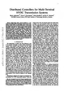
The approach proposed in this paper for ac/dc power flow is used on the benchmark test system (Fig. 8) to evaluate the steady state performance.
Fig. 8. Basic structure of the benchmark test system for Phase I of Supergrid Project. In this system the energy from wind generation clusters off the east coast of the UK will be collected at SuperNodes at Firth of Forth, Dogger Bank/Hornsea and Norfolk Bank which will be connected together and interconnected with the German and Belgian North Sea clusters and Norwegian Hydro Power. The network then will deliver this power to the existing networks at terminals at Glasgow, Hull and Zeebrugge and nodes at London and Southern Germany (or North Rhine Westphalia). Fig. 9 shows a summary ac/dc power flows expected for the different interconnections and nodes involves on the Phase I of Supergrid. This is high-generation scenario based on connecting 23,000 MW of offshore wind from the Firthof-Forth, Dogger-Hornsea, Norfolk Bank, German and Belgian Offshore clusters and using technology expected to
UK1
4
VSC4
5.10 5ac
27.3 UK2
VSC5
VSC1
5GW
0.70
2
5.50 UK3
VSC6
6
VSC3
4.26
9 3-9
VSC7
7
1.86
VSC9
10.00
9ac
10GW
8
German WF 10.00 VSC8
8ac
G3
8.75 Norfolk Bank 2.00
Germany
Pac Qac Pdc
G9
WF
G2
2GW
7ac
G10 VSC10
Dogger Bank 3ac 5.00 WF
G7
2.22
VSC2
3-6
27.26
Zeebrugge
3
5GW
London
Belgium
WF 5GW
4.73
13.60
5GW
10GW
2ac
4.70
G1
10ac
2-10
Firth of Forth 3.60 1.15
5GW
6ac
4.0
4.30
2-5
30.8
10
WF
5
Hull
16.8
1ac
5GW
5.30
Norway
5.00
1
1-4
Glasgow
TABLE I. INTERCONNECTION AND NODE CAPACITIES [33] Connection Dogger-Germany Offshore Dogger-Norfolk Bank Dogger-Firth of Forth Dogger-Norway Germany Offshore-Munich London-Norfolk Bank Norfolk Bank-Belgium Offshore Nodes Belgium Offshore Dogger-Hornsea Germany Offshore Norfolk Bank Munich Firth of Forth
4ac
4.50
43.45 G8
35.00
www.fglongatt.org.ve
Francisco Gonzalez-Longatt, PhD May 2012 United Kingdom
Fig. 9. AC/DC Power flow results for the benchmark test system for Phase I of Supergrid Project: High Generation Scenario
Scenario depicted on Fig. 9 shows how the MTDC offshore transmission network is used to link the hydro resources of Scandinavia with the marine and wind resources of Northern Europe. In this case, 3.6 GW is traded between England area and Norway area, based on the electricity market. The German wind farm contributes 10GW, 1.15 GW goes to the Supergrid market, and 8.89 GW will be injected in the Germany and North Europe power system. The scenario looks unrealistic a first glance (the highest amount of wind power production) however, results demonstrate technical feasibility of heavy power flow interchanges between parties involved. Power flow injection at converter substations and undersea cables are kept below rated power. Results show an interesting technical and economic problem in terms of power losses on dc grid and converter station. The concept of unique slack bus on multi-terminal dc system creates a dilemma, which one will be dc node responsible for total power losses? This is a non trivial question and there is not straight-forward answer. There are several aspects to be considered, beyond the scope of this paper: the contracted transmission capacities, line limits and the power balance between the multiple synchronous grids are connected. V. CONCLUSIONS This paper presents an algorithm for the solution of ac/dc power flow for the analysis of multi-terminal voltage source converter HVDC (VSC-MTDC) systems. This algorithm is described as sequential ac/dc power flow, which can be implemented easily in an existing ac power flow package and is very flexible when it compared with unified methods. The algorithm proposed in this paper is a general approach for analysis ac/dc power flows including loss-less VSC. The main contribution of this paper is development of sequential algorithm which uses the Gauss-Siedel algorithm to solve dc power balance equations, it offers two keys advantages: very fast and simple computational implementation. The algorithm presented in this paper is implemented on MATLAB® and
integrated into Power System Toolbox (PST). The algorithm is tested using the WSCC 3-machine, 9-bus system with a 3-terminal MTDC network and results compared with those obtained from DIgSILENT® proposed algorithm. Results of the numerical simulation on this test network show the validity of the algorithm to include VSC MTDC system into an ac network. The author introduced a benchmark test system for the Phase I of Supergrid, the proposed algorithm is used to calculate dc power flows, results show the technical feasibility of heavy power flows interchanges between parties involved. ACKNOWLEDGEMENTS The authors gratefully acknowledge the contributions of Mr. Mr. Temesgen M. Haile Selassie from Norwegian University of Technology and Science for his strong supports on Udc-P controllers and Mr. Jef Beerten from the Katholieke Universiteit Leuven for his support providing data for the dc test case. REFERENCES [1] P. O'Kane, "European Offshore SuperGrid – Creating a More Powerful Europe," presented at the CIEP Seminar 'Standard grids, smart grids, super grids: All the same, all different, complementary, not compatible?', Clingendael Institute, 2007. [2] F. Gonzalez-Longatt;, J. Roldan;, and C. A. Charalambous, "Power Flow Solution on Multi-Terminal HVDC Systems: Supergid Case," presented at the International Conference on Renewable Energies and Power Quality (ICREPQ’12), Santiago de Compostela, Spain, 2012. [3] EWEA. (2011). European Wind Energy Association: Policy/Project Offshore Wind. Available: http://www.ewea.org/index.php?id=203 [4] L. Weixing and O. Boon Teck, "Multi-terminal DC transmission system for wind-farms," in Power Engineering Society Winter Meeting, 2001. IEEE, 2001, pp. 1091-1096 vol.3. [5] T. Nakajima and S. Irokawa, "A control system for HVDC transmission by voltage sourced converters," in Power Engineering Society Summer Meeting, 1999. IEEE, 1999, pp. 1113-1119 vol.2. [6] T. M. Haileselassie, M. Molinas, and T. Undeland, "Multi-Terminal VSC-HVDC System for Integration of Offshore Wind Farms and Green Electrification of Platforms in the North Sea," presented at the Nordic Workshop on Power and Industrial Electronics, Espoo, Finland., 2008. [7] R. L. Hendriks, G. C. Paap, and W. L. Kling, "Control of a multiterminal VSC transmission scheme for connecting offshore wind farms," in European Wind Energy Conference, Milan, Italy, 2007. [8] D. Jovcic, "Interconnecting offshore wind farms using multiterminal VSC-based HVDC," in Power Engineering Society General Meeting, 2006. IEEE, 2006, p. 7 pp. [9] J. Arrillaga and P. Bodger, "Integration of h.v.d.c. links with fastdecoupled load-flow solutions," Electrical Engineers, Proceedings of the Institution of, vol. 124, pp. 463-468, 1977. [10] M. M. El-Marsafawy and R. M. Mathur, "A New, Fast Technique for Load-Flow Solution of Integrated Multi-Terminal DC/AC Systems," Power Apparatus and Systems, IEEE Transactions on, vol. PAS-99, pp. 246-255, 1980. [11] K. R. Padiyar and V. Kalyanaraman, "Power Flow Analysis in MTDCAC Systems- New Approach," Electric Machines & Power Systems, vol. 23, pp. 37-54, 1995/01/01 1995. [12] J. Reeve, G. Fahny, and B. Stott, "Versatile load flow method for multiterminal HVDC systems," Power Apparatus and Systems, IEEE Transactions on, vol. 96, pp. 925-933, 1977. [13] M. E. El-Hawary and S. T. Ibrahim, "A new approach to AC-DC load flow analysis," Electric Power Systems Research, vol. 33, pp. 193-200, 1995. [14] A. Ugur, "The power flow algorithm for balanced and unbalanced bipolar multiterminal ac–dc systems," Electric Power Systems Research, vol. 64, pp. 239-246, 2003.
[15] T. M. Haileselassie and K. Uhlen, "Power flow analysis of multiterminal HVDC networks," in PowerTech, 2011 IEEE Trondheim, 2011, pp. 1-6. [16] J. Beerten, S. Cole, and R. Belmans, "Implementation aspects of a sequential AC/DC power flow computation algorithm for Multiterminal VSC HVDC systems," in AC and DC Power Transmission, 2010. ACDC. 9th IET International Conference on, 2010, pp. 1-6. [17] J. Beerten, S. Cole, and R. Belmans, "A sequential AC/DC power flow algorithm for networks containing Multi-terminal VSC HVDC systems," in Power and Energy Society General Meeting, 2010 IEEE, 2010, pp. 1-7. [18] J. Beerten, D. Van Hertem, and R. Belmans, "VSC MTDC systems with a distributed DC voltage control - A power flow approach," in PowerTech, 2011 IEEE Trondheim, 2011, pp. 1-6. [19] P. M. Anderson and A. A. Fouad, Power System Control and Stability, 2nd ed. New York: IEEE Press, 2003. [20] DIgSILENT, "DIgSILENT PowerFactory," 14.0.524.2 ed. Gomaringen, Germany, 2011. [21] F. Milano, Power system modelling and scripting, 1st ed. New York: Springer, 2010. [22] H. E. Brown, Solution of large networks by matrix methods, 2nd ed. ed. New York ; Chichester: Wiley, 1985. [23] J. Arrillaga and C. P. Arnold, Computer analysis of power systems. Chichester, England ; New York: Wiley, 1990. [24] E. Acha, FACTS : modelling and simulation in power networks. Chichester: Wiley, 2004. [25] MATLAB, version 7.12.0.635 (R2011a 64-bit) Natick, Massachusetts: The MathWorks Inc., 2011. [26] K. W. Cheung and J. Chow. (1990). Power System Toolbox (PST). Available: http://www.ecse.rpi.edu/pst/PST.html [27] FOSG. (2011). Friends of the Supergrid. Available: http://www.friendsofthesupergrid.eu/ [28] D. Van Hertem, M. Ghandhari, and M. Delimar, "Technical limitations towards a SuperGrid: A European prospective," in Energy Conference and Exhibition (EnergyCon), 2010 IEEE International, 2010, pp. 302309. [29] K. Rudion, A. Orths, P. B. Eriksen, and Z. A. Styczynski, "Toward a Benchmark test system for the offshore grid in the North Sea," in Power and Energy Society General Meeting, 2010 IEEE, 2010, pp. 1-8. [30] D. Foundation. Clean power from deserts – The DESERTEC Concept for energy, water and Climate security. Available: www.desertec.org/downloads/articles/trec_white_paper.pdf [31] A. Woyte, J. D. Decker, and T. Vu Van. (2008). North Sea electricity grid [r]evolution – Electricity output of interconnected offshore wind power: a vision of offshore wind power integration. Greenpeace – 3E, 2008. Available: http://www.greenpeace.org/raw/content/eu-unit/presscentre/reports/A-North-Sea-electricity-grid-%28r%29evolution.pdf [32] T. K. Vrana, R. E. Torres-Olguin, B. Liu, and T. M. Haileselassie, "The North Sea Super Grid - a technical perspective," in AC and DC Power Transmission, 2010. ACDC. 9th IET International Conference on, 2010, pp. 1-5. [33] FOSG. (2010). Friends of Supergrind. Position paper on the EC Communication for a European Infrastructure Package. Available: http://www.friendsofthesupergrid.eu/documentation.aspx
BIOGRAPHIES Francisco M. González-Longatt (S’01, M’03, SM’ 2009) was born in Cagua-Venezuela, on July 30, 1972. He graduated on Electrical Engineering of Instituto Universitario Politécnico de la Fuerza Armada Nacional, Venezuela (1994), and Master of Business Administration of Universidad Bicentenaria de Aragua, Venezuela (1999) and PhD of Universidad Central de Venezuela (2008). His main area of interest is integration of intermittent renewable energy resources into smart grid with special interest on dynamic behavior. He is former associate professor on Electrical engineering Department of Universidad Nacional Politécnico de la Fuerza Armada Nacional, Venezuela. He is currently a Post Doctoral Associate Research School of Electrical and Electronic Engineering, The University of Manchester.
Juan Manuel Roldan was born in Sevilla-Spain, on June 14, 1976. He is electrical engineer graduated on Industrial Engineering of Escuela de Ingenieros, University of Seville, Spain (2003). He received the M.Sc. degree in electrical engineering from the University of Seville (2011). He has been working as electrical engineer in the fields of control, protection and substation design in Spain and UK since 2004. He is currently working towards the PhD degree at the University of Seville and he was a visitor PhD researcher on The University of Manchester on 2011. His main area of interest is integration of intermittent renewable energy resources into power grid using multi-terminal HVDC systems. Charalambos A. Charalambous (M’08) was born in Nicosia, Cyprus in 1979. He received a Class I BEng (Hons) degree in Electrical & Electronic Engineering in 2002 and a PhD in Electrical Power Engineering in 2005 from UMIST, UK (The University of Manchester). Currently, he is an Assistant Professor, in the Department of Electrical and Computer Engineering, at the University of Cyprus. He was formerly with the National Grid High Voltage Research Center at the University of Manchester, UK. His research interests include transformer finite element modeling, Ferroresonance transient studies, the electrical control and analysis of DC corrosion and the dynamic - life cycle - evaluations of power system operation and costs .