of this work, there were explained in detail the main original methods used in applet codes. Key-Words: - HTML, Java applets, Interference, Single-slit diffraction, ...
Proceedings of the 10th WSEAS International Conference on MATHEMATICAL and COMPUTATIONAL METHODS in SCIENCE and ENGINEERING (MACMESE'08)
Some Aspects in the Modelling of Physics Phenomena using Computer Graphics LIVIA SANGEORZAN1, MIRCEA PARPALEA3, ANISOR NEDELCU2, COSTEL ALDEA1 1 Department of Computer Science 2 Department of Technological Engineering Transilvania University of Brasov 25, Eroilor, blvd, 500030, Brasov 3 National College “Andrei Saguna” 1, Muresenilor, street, 590000, Brasov ROMANIA
Abstract: - The present paper aims to realize a set of applets embedded in HTML pages, with the purpose of illustrating the main elements connected to interference and diffraction of light phenomena. Using Swing (Java) on developed applets for: Young interference and single-slit diffraction of monochromatic light as well as of natural light. In the end of this work, there were explained in detail the main original methods used in applet codes. Key-Words: - HTML, Java applets, Interference, Single-slit diffraction, Swing, Young's double-slit experiment approximately equal amounts of red, green, and blue light. Human color perception is dependent upon the interaction of all receptor cells with light, and this combination results in nearly tri-chromic stimulation.
1 Introduction The interference and diffraction of light phenomena are easier to be understood in an interactive way. In order to point out the main elements concerning these physics phenomena, two applets which were embedded in HTML pages were developed. These applets are built in Java language using: Applet and swing classes ([1], [2]). Swing was a widget toolkit for Java. Swing provides a sophisticated set of GUI (Graphical User Interface) components. The developed Swing Applets reveal the following aspects: Young's double-slit experiment, Cornu spiral and single-slit diffraction
2 Theoretical Aspects Some theoretical aspects regarding the equation which describe the physics phenomena and which are implemented in the applets of the application will be presented in summary. The phenomena which were taken in account are the following: natural light spectrum generation, interference of monochromatic and natural light, Young's double-slit experiment, diffraction of monochromatic and natural light, Cornu spiral ([3], [4])
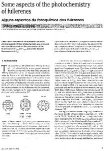
Fig.1 Absorption Spectra of Human Visual Pigments There are shifts in color sensitivity with variations in light levels, so that blue colors look relatively brighter in dim light and red colors look brighter in bright light. The cone response sensitivities at each wavelength shown as a proportion of the peak response, which is set equal to 1.0 on a linear vertical scale, is called Linear Normalized Cones Sensitivities ([6]). This produces the three similar (but not identical) curves shown in Fig. 2. This representation is in some respects misleading, because it distorts the functional relationships between light wavelength (energy), cone sensitivity and color perception. However, comparison with the photopigment absorption curves above identifies some obvious differences between the shape and peak sensitivity of the photo-pigment and cone fundamentals.
2.1 RGB generation of natural light spectrum Illustrated in Fig. 1 are the absorption spectra of the four human visual pigments, which display maxima in the expected red, green, and blue regions of the visible light spectrum. When all three types of cone cell are stimulated equally, the light is perceived as being achromatic or white ([5]). For example, noon sunlight appears as white light to humans, because it contains ISSN: 1790-2769
518
ISBN: 978-960-474-019-2
Proceedings of the 10th WSEAS International Conference on MATHEMATICAL and COMPUTATIONAL METHODS in SCIENCE and ENGINEERING (MACMESE'08)
interference generated is the same as with a single source. Let I1 and I2 be two synchronous sources of monochromatic light of the same wavelength λ. In any point of the line that bounds the two sources will arrive the interfering waves:
Overall, human spectral sensitivity is split into two parts: a peaked short wavelength sensitivity centered on "blue violet" (445 nm), and a broad long wavelength sensitivity centered around "yellow green" (~560 nm), with a trough of minimum sensitivity in "middle blue" (475 to 485 nm)
t d ⎞ y 1 = a1 ⋅ cos 2π ⎛⎜ − 1 ⎟ = a1 cos(ωt − ϕ1 ) ⎝T λ ⎠
(1)
t d ⎞ y 2 = a2 ⋅ cos 2π ⎛⎜ − 2 ⎟ = a2 cos(ωt − ϕ 2 ) ⎝T λ ⎠
(2)
Their phase difference is
Δϕ = ϕ1 −ϕ2 = 2π(d1 − d2 )/λ = 2πδ/λ
Fig. 2 Normalized Cone Sensitivity Functions
2.2
y = y 1 + y 2 = A ⋅ cos(ωt − ϕ )
Interference of light
(4)
which leads to
In physics, interference is the addition (superposition) of two or more waves that result in a new wave pattern. As most commonly used, the term interference usually refers to the interaction of waves which are correlated or coherent with each other, either because they come from the same source or because they have the same or nearly the same frequency. Two non-monochromatic waves are only fully coherent with each other if they both have exactly the same range of wavelengths and the same phase differences at each of the constituent wavelengths. When interfering, waves add constructively or subtract destructively, depending on their relative phase. Two waves are said to be coherent if they have a constant relative phase, which also implies that they have the same frequency. The degree of coherence is measured by the interference visibility, a measure of how perfectly the waves can cancel due to destructive interference. The total phase difference is derived from the sum of both the path difference and the initial phase difference (if the waves are generated from two or more different sources). It can then be concluded whether the waves reaching a point are in phase (constructive interference) or out of phase (destructive interference). The principle of superposition of waves states that the resultant displacement at a point is equal to the vector sum of the displacements of different waves at that point. If a crest of a wave meets a crest of another wave at the same point then the crests interfere constructively and the resultant wave amplitude is greater. If a crest of a wave meets a trough of another wave then they interfere destructively, and the overall amplitude is decreased. This form of interference can occur whenever a wave can propagate from a source to a destination by two or more paths of different length. Two or more sources can only be used to produce interference when there is a fixed phase relation between them, but in this case the
ISSN: 1790-2769
(3)
where δ is the path difference. The resulting vibration is given by:
A2 = a12 + a22 + 2 a1 a2 cos(ϕ1 − ϕ 2 ) 2
(5)
As the intensity of wave is J≈A , Jmax ≈ (a1+a2)2 if Jmin ≈ (a1-a2)2 if
2.3
Δϕ = 2kπ or δ = kλ
Δϕ = (2k + 1)π or δ = (2k + 1)λ /2
(6) (7)
Young's double-slit experiment
THOMAS YOUNG provided the first practical demonstration of optical interference in 1801. His experiment gave a very strong support to the wave theory of light. Experimental arrangement 'S' is a slit, which receives light from a source of monochromatic light. As 'S' is a narrow slit so it diffracts the light and it falls on slits A and B. After passing through the two slits, interference between two waves takes place on the screen. The slits A and B act as two coherent sources of light. Due to interference of waves, alternate bright and dark fringes are obtained on the screen. Quantitative analysis Let the wavelength of light = λ. Consider a point P on the screen where the light waves coming from slits A and B interfere such that PC = y. The wave coming from A covers a distance AP = r1 and the wave coming from B covers a distance BP = r2 such that PB is greater than PA .
Fig.3 Young's double-slit experiment
519
ISBN: 978-960-474-019-2
Proceedings of the 10th WSEAS International Conference on MATHEMATICAL and COMPUTATIONAL METHODS in SCIENCE and ENGINEERING (MACMESE'08)
a variation in refractive index for light waves or in acoustic impedance for sound waves and these can also be referred to as diffraction effects. While diffraction occurs whenever propagating waves encounter such changes, its effects are generally most pronounced for waves where the wavelength is on the order of the size of the diffracting objects. The complex patterns resulting from the intensity of a diffracted wave are a result of the superposition, or interference of different parts of a wave that traveled to the observer by different paths.
Path difference = BP - AP = BD; s = r2 - r1 = BD In right angled ΔBAD (Fig.3) and we have sin(θ)=BD/AB (8) or s=d·sin(θ) (9) Since the value of ’d’ is very small as compared to L, therefore, θ will also be very small. In this condition, we can assume that sinθ = tanθ. In right angled Δ PEC we have tan(θ) = PC/EC = y/L. (10) Using the value of tan(θ) from equation (10) in equation (8), we obtain s = d·y/L or y = s·L/d. (11) For bright fringe s=m·λ. Therefore, the position of bright fringe is: y = m·λ·L/d. For destructive interference, path difference between two waves is (m+1/2)·λ. Therefore, the position of dark fringe is: y = (m+1/2)·λ·L/d (12)
The mechanism of diffraction Diffraction arises because of the way in which waves propagate; this is described by the Huygens–Fresnel principle. The propagation of a wave can be visualized by considering every point on a wave front as a point source for a secondary radial wave. The subsequent propagation and addition of all these radial waves form the new wave front. When waves are added together, the relative phases as well as the amplitudes of the individual waves determine their sum, an effect that is often known as wave interference. The summed amplitude of the waves can have any value between zero and the sum of the individual amplitudes. Hence, diffraction patterns usually have a series of maxima and minima. To determine the form of a diffraction pattern, we must determine the phase and amplitude of each of the Huygens wavelets at each point in space and then find the sum of these waves. There are various analytical models which can be used to do this including the Fraunhoffer diffraction equation for the far field and the Fresnel diffraction equation for the near-field. Most configurations cannot be solved analytically; solutions can be found using various numerical analytical methods including Finite element and boundary element methods.
Fringe spacing The distance between any two consecutive bright fringes or two consecutive dark fringes is called fringe spacing. Fringe spacing or thickness of a dark fringe or a bright fringe is equal and it is denoted by Δx. Δx = λ L/d
(13)
Slit dimension Fringes will be sharp if the dimensions of the light sources are extremely small, in fact, smaller than the wavelength. This reduces the light beam and, because of the diffraction phenomenon spreads so much that, the intensity of light falls beyond the sensibility limit of the receptor. Using larger slits, in order to increase visibility, can cause the disappearance of the fringes. However, as light sources, usually are used slits with a width smaller than Δx/4. Interference of natural (white) light Using a source of natural light, which is continuously emitting radiations with wavelengths between λRed ≈ 760 nm and λViolet ≈ 400 nm, will cause a single central white fringe, all other fringes being coloured from violet to red and expanding with the increasing of the interference order. As a result of the above described situation, fringes will come to overlap obtaining an almost uniform white colour screen called white of higher order.
Fresnel Number Fresnel number is the dimensionless parameter a2 (14) F= λ⋅R where a is the characteristic size ("radius") of the aperture, λ is the wavelength, and R is the distance from the aperture. The F